Page is loading ...

Please read this instruction manual
carefully before using this product, par-
ticularly the section describing safety
Retain this instruction manual with the
productfor further consultation when-
ever necessary

1
To use this product safety, basic knowledge of pneumatic
equipment, including materials, piping, electrical system
and mechanism, is required (ISO 4414 *1, JIS B 8370 *2).
We do not bear any responsibility for accidents caused by
any person without such knowledge or arising from im-
proper operation.
Our customers use this product for a very wide range of
applications, and we cannot keep track of all of them. De-
pending on operating conditions, the product may fail to
operate to maximum performance, or cause an accident.
Thus, before placing an order, examine whether the product
meets your application, requirements, and how to use it.
This product incorporates many functions and mecha-
nisms to ensure safety. However, improper operation could
result in an accident. To prevent such accidents,
Observe the cautions on handling described in this man-
ual, as well as the following instructions:
l
*1) ISO 4414 : Pneumatic fluid power Recommendations for
the application of equipment to transmission and
control systems.
*2) JIS B 8370 : General rule for pneumatic systems

2
INDEX
HMVC2, HSVC2
HMVO2, HSVO2
Manually Controlled Valves
Manual No. SM-154037-A
1. PRODUCT
1.1 Specifications 3
1.2 External dimensions and JIS Symbol 3
1.3 Fundamental circuit diagram 5
2. CAUTION
2.1 Fluid 7
3. OPERATION
3.1 Mounting a handle bar 8
3.2 Shifting the direction of flow 8
4. INSTALLATION
4.1 Piping 9
4.2 Tightening torque 9
4.3 On panel mounting 9
5. MAINTENANCE
5.1 Disassembling 10
6. HOW TO ORDER 12

3
1.1 Specifications
Item Specifications
Media Compressed air
Fluid temperature 5 to 50
Ambient temperature -5 to 50 (Not to be frozen)
Working pressure range 0 to 1.0MPa
Proof pressure 1.5 MPa
Effective sectional area
1.2 External dimensions and JIS Symbol
1) External dimensions
l HMVC2-8-4H, 4V
l HMVO2-8-4H, 4V
Model No.
Item HMV 2 HSV 2
Port size Rc
1/8 1/8 1/4
3/8
1/2
Effective sectional area
mm2
8 40 50 55 55
C
O
C
O
50
52
68
30
52
68
102
80
34
13
6
83
Make the dia. of 51 when cutting a panel hole.
(74)
(74)
4-5.5
4-M5
Depth 9
4-Rc1/4
(2 V : Vertical porting type
Plug built-in)
4-Rc1/4
(2 V : Vertical
porting type)
4-Rc1/4
Plug as built-in
(2 V : Vertical
porting type)

4
l HSVC2-8 to 20-4H
l HSVO2-8 to 20-4H
Symbol
Model No. A B C D E F
HSV 2-8 to 15-4H 132 105 42 15 6 98
HSV 2-8 to 15-4V 132 105 42 15 6 104
HSV 2-20-4H 137 110 47 18 10 98
2) JIS Symbol
l HMVC2, HSVC2 (All port blocked)
l HMVO2, HSVO2 (CYL1, CYL2, EXH. Connection)
Position
Position
55
80
F
80
F
4-6.5
4-M6
Depth 11
A
B
C
D
E
130
Make the dia. of 78 when cutting a panel hole.
(F)
(F)
4-2
(3 V : Vertical
porting type)
4-2
(3 V : Vertical porting type
Plug built-in)
4-Rc1/4
Plug as built-in
(3 V : Vertical
porting type)

5
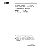
1.3 Fundamental circuit diagram
Normal application of manually operated directional control valve is as per
illustrated below, generally
Fig.1. An example of All ports blocked valve circuit
Fig.2. An example of ABR ports valve circuit
Fig.3. An example of ABR ports valve circuit combined with a master valve
Speed
controller
Double-acting
cylinder
Air filter + regulator
+ pressure gage
Compressed air
Manual control valve
(All ports block type)
Manual control valve
(A, B & R connecting type)
Speed
controller
Double-acting
cylinder
Air filter + regulator
+ pressure gage
Compressed air
Manual control valve
(A, B & R connecting type)
Master valve
Speed
controller
Double-acting
cylinder
Air filter + regulator
+ pressure gage
Compressed air

6
CAUTION
1. Make sure to use “IN” port to supply compressed air to the manual shifting
valve. There will be internal leakage otherwise.
2. Due to non-elastic seals being used to build the main valve (manual shifting),
internal leakage of valve is estimated to be fairly noticeable volume as follows
(although it is to be about 1/10of it at ex-factory).
HMV type = Below 500Ncm3/min ANR
HSV type = Below 1000Ncm3/min ANR
Beware, therefore, cylinder may slide when it is left for long at an intermedi-
ate stop position when circuit is built with all ports blocked valve.
As for a counter measure. it is recommended to combine a master valve (in-
ternal leakage below 10Ncm3/min ANR) (FIG. 3).
3. For only two-position operation, use a manual shifting valve, all ports blocked
and shift it to either “1” or “2” only, passing over the position “N” (neutral).

7
2.1 Fluid
1) It is necessary to use dehumidified
air that has been filtered from com-
pressed air. Carefully select an
adequate filter that has an adequate
filtration rate (preferably 5 m or
less), flow rate and its mounting lo-
cation (as nearest to the directional
control valve as possible).
2) Be sure to drain out the accumula-
tion in the filter periodically.
3) Note that the intrusion of carbide for the compressor oil (such as carbon or
tarry substance) into the circuit causes malfunction of the solenoid valve and
the cylinder. Be sure to carry out thorough inspection and maintenance of
the compressor.
4) Use “Turbine oil, class 1, ISO VG32” or equivalent, when lubrication is re-
qired.
5) Within the ambient of much dusts or small particles, prevent them from fal-
ling into circuit system by installing a silencer at Exh. port or similar
measure.
Drain
Upper Limit
of drain
Compressed air
Air filter
Fi
l
trated air

8
3.1 Mounting a handle bar
Screw the handle ass’y with a red ball at a handle end into tapped thread
on the handle head tightly. (Loosen play wears out thread shortly.)
3.2 Shifting the direction of flow
Control it with this handle bar. Swing the bar until it clicks at required
marking such as 1, 2 or Neutral.
Direction of flow is shifted as follows by the number the arrow mark points.
When it points 1 : IN CYL1, CYL2 EXH
When it points 2 : IN CYL2, CYL1 EXH
When it points N : All ports are blocked (HMVC2 & HSVC2)
: CYL 1, CYL 2 & EXH. Ports Connection (HMVO2 & HSVO2)
Handle head
Handle ass’y

9
4.1 Piping
1) For piping beyond the filter, use pipes that hardly get corroded such as gal-
vanized pipes, nylon tubes, rubber tubes, etc.
2) Be sure observe the effective thread
length of gas pipe and give a chamfer of
approx. 1/2 pitch from the threaded
end.
3) Flush air into the pipe to blow out for-
eign substances and chips before piping.
4) Refrain from applying sealant or sealing tape approx. two pitches of thread
off the tip of pipe to avoid residual substances from falling into piping system.
4.2 Tightening torque
Apply the torque range as
specified in the table to the
right so as to prevent air leak-
age and possible damage as
well.
4.3 On panel mounting
For on panel mounting, use the following mounting screws respectively, re-
ferring to “1-2 External dimensions drawing”. 4 M6 screws for HSV as well
as 4 M5 screws for HMV
Port dia Appropriate
tightening torque Nm
Rc1/4 6 to 8
Rc3/8 13 to 15
Rc1/2 16 to 18
Rc3/4 18 to 21
Correct
Incorrect
Correct
Incorrect
Seal
Tape
Sealant (Paste or liquid)
Chamfer
Effective Length

10
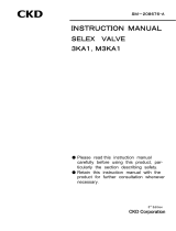
5.1 Disassembling
1) Reference drawin
HMVC2
HSVC2
CAUTION at assembling
When building this unit, make those three points match with
each other such as IN mark on cover , projected point on
slide ring and projected point on body .
No.
Name of parts Material
Qty
Note No.
Name of parts Material
Qty
Note
Body ass’y ZDC2
1
Washer PE 1
Cover ass’y ZDC2
1
Ball SUS304
1
Handle head ZDC2
1
Spring SUS304
1
Handle ass’y SS41 1
O ring NBR 1 JISB2401G75 (G45)
Slide ring ZDC2
1
O ring NBR 1 JISB2401P12 (P5)
Plate ass’y SPCC
1
Pin SS41 1
Cross headed pan SWRM
4(3)
Rod SS41 1
Hexagon socket
plug SS400
4 Use this port for
vertivcal piping (V).
Spindle SS41 1
Spring SWP 1
Hexagon socket
head cap screw SCM3
4 M6 12 (M5 12)
(specs) are for model HMVC2
Casted out
letters “IN”
Projection
marking
21

11
HMVO2
HSVO2
CAUTION at assembling
When building this unit, make those three points match with
each other such as IN mark on cover , projected point on
slide ring and projected point on body .
No.
Name of parts Material
Qty
Note No.
Name of parts Material
Qty
Note
Body ass’y ZDC2
1
Washer PE 1
Cover ass’y ZDC2
1
Ball SUS304
1
Handle head ZDC2
1
Spring SUS304
1
Handle ass’y SS41 1
O ring NBR 1 JISB2401G75 (G45)
Slide ring ZDC2
1
O ring NBR 1 JISB2401P12 (P5)
Plate ass’y SPCC
1
Pin SS41 1
Cross headed pan SWRM
4(3)
Spindle guide SPCC
1(0)
Rod SS41 1
O ring NBR 2 JISB2401P7 (KS2)
Spindle SS41 1
Spring SWP 1
O ring NBR 1 JISB2401G65
(special)
Hexagon socket
plug SS400
4 Use this port for
vertivcal piping (V).
Hexagon socket
head cap screw SCM3
4 M6 12 (M5 12)
(specs) are for model HMVO2
2) Apply Silicone grease to every sliding metal part such as Slide ring, Steel ball,
Spindle, O ring etc when assembling the valve.
Projection
marking
Casted out
letters “IN”
21

12
(a) (b) (c) (d)
(a) Type (b) Operator type (c) Port size (d) Piping
M Miniature C Three position all ports blocked 8 Rc1/4 H Horizontal pip-
ing
S Standard O Three position ABR port connection
10 Rc3/8 V Vertical piping
15 Rc1/2
20 Rc3/4 Vertical piping of dia.
20 is unavailable.
Connecting ports of
HMV type is Rc1/4
only.
/