Page is loading ...

Please read this instruction manual
carefully before using this product, par-
ticularly the section describing safety
Retain this instruction manual with the
product for further consultation whenever
necessary

1
To use this product safety, basic knowledge of pneumatic
equipment, including materials, piping, electrical system and
mechanism, is required (to the level pursuant to JIS B 8370
Pneumatic System Rules).
We do not bear any responsibility for accidents caused by any
person without such knowledge or arising from improper opera-
tion.
Our customers use this product for a very wide range of applica-
tions, and we cannot keep track of all of them. Depending on op-
erating conditions, the product may fail to operate to maximum
performance, or cause an accident. Thus, before placing an order,
examine whether the product meets your application, require-
ments, and how to use it.
This product incorporates many functions and mechanisms to
ensure safety. However, improper operation could result in an
accident. To prevent such accidents,

2
INDEX
SC1-6 8 10 15
Speed Controller
Manual No. SM-1683-A
1. PRODUCT
1.1 Specification 3
1.2 External Dimension ,
Internal structure and Symbol 3
1.3 Fundamental Circuit Diagram 4
2. CAUTION
2.1 Fluid 5
3. OPERATION 6
4. INSTALLATION
4.1 Piping 7
5. MAINTENANCE
5.1 Trouble shooting 9
6. HOW TO ORDER 9

3
1.1 Specifications
Item Universal Type High Temperature Type
Media Compressed air
Proof pressure MPa
1.5
Working pressure range MPa
0.05 to 1.0
Fluid temperature
5 to 60 5 to 120
Ambient temperature
0 to 60 (Not to be frozen) 5 to 120 (Not to be frozen)
Cracking pressure MPa
0.05 or less
Effective sectional area
Model No.
Effective sectional area (mm2) SC1-6 SC1-8 SC1-10 SC1-15
Free flow 11 14 39 43
Controlled flow 8 13 22 36
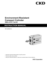
1.2 External dimensions, Internal structure and JIS symbol
1) External dimensions
Markings
Model code A B C D E F G H I J K
SC1-6, 8 50 20 42 31 23 11 67 22 12 31 19
SC1-10, 15 63 21 55 40 31 15 83 30 18 37 23
Mounting bolt hole
(pass through)
2-4.5
Mounting screws 2
-
M4 Depth 6 (SC1
-
6
8)
2-M5 Depth6 (SC1-10 15)
Connecting port diam
6 : Rc1/8
8 : Rc1/4
10 : Rc3/8
15 : Rc1/2

4
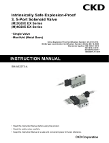
2) Internal structure and major parts list
No.
Part name Material Remark
1 Needle C3604BD
2 E type snap ring
SK5
3 Knob ZDC2
4 Needle guide ADC12
5 Lock nut ZDC2
6 O ring NBR
7 Gasket NBR
8 Body ADC12
9 Spring SUS304WP
10
Valve seat NBR,C3604BD
However, for the
high-
temperature
type, the mate-
rial (NBR) for
Parts Nos. 6, 7 &
10 should be
“FKM”.
3) JIS Symbol
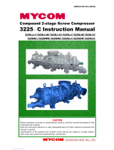
1.3 Fundamental circuit diagram
The fundamental circuit diagram for speed controller is as per shown below.
(Meter out connection)
Silencer
Double
-
acting
cylinder
Pressure
gage
Regulator
Selex valve
Speed co
n-
troller
Compressed
air
Filter

5
2.1 Fluid
1) Use the compressed air, filtrated and
dehumidified. Carefully select a filter
of an adequate filtration rate (5 m or
lower preferred), flow rate and its
mounting location (asclosest to direc-
tional control valve as possible)
2) Be sure to drain out the accumulation
in filter periodically.
3) Note that the intrusion of carbide of
compressor oil (such as carbon or tarry
substance) into the circuit causes
malfunction of solenoid valve and cyl-
inder. Be sure to carry out thorough
inspection and maintenance of com-
pressor.
Compressed air
Filtrated air
Drain
Upper limit of
drain

6
Turning the handle clockwise re-
duces the speed of cylinder, finally
closing the controller, while turning it
counterclockwise increases the speed
of cylinder. To build a meter out cir-
cuit, close the controller first by turn-
ing its handle clockwise, then con-
nect it to the piping so that the casted
JIS symbol on the body matches
with the direction of flow as per des-
igned schematic.
While giving pressure to the circuit, turn the handle of controller
counterclockwise until the required speed of the cylinder is set. Once the
position of the handle is set, make sure to tighten up the lock nut .
The cylinder will no longer gain its speed after the handle is turned ap-
prox. 8 to 10 times from the fully closed position as the controller gets out
of the controllable range of speed.
Open Close
JIS symbol marking
(Meterout connection)
Silencer
Double
-
acting
cylinder
Pressure
gage
Regulator
Selex valve
Speed
cpntroller
Compressed
aire
Filter

7
4.1 Piping
1) For piping beyond the filter, use pipes that are tough against corrosion such
as galvanized pipes, nylon tubes, rubber tubes, etc. (Refer to Selection
Guide Table for Related Equipment.)
2) See to it that the pipe connecting cylinder and solenoid valve has effective
sectional area which is needed for the cylinder to drive at the specified speed.
(Refer to Selection Guide Table for Related Equipment.)
3) Install filter preferably adjacent to the
upper-stream to the solenoid valve for
eliminating rust, foreign substance in
the drain of the pipe.
4) Be sure observe the effective thread
length of gas pipe and give a chamger
of approx. 1/2 pitch from the threaded
end.
5) Flush air into the pipe to blow out for-
eign substances and chips before piping.
6) Refrain from mapplying sealant or sealing tape approx. two pitches of thread
off the tip of pipe to avoid residual substances from falling into piping sys-
tem.
Correct
Incorrect
Correct
Incorrect
Seal Tape Sealant (Paste or liquid)
Cha
m
fer
Effective Length

8
7) For the prevention of the leakage and breakage, tighten the screw within the
limits of the adequate tightening torque mentioned below.
Tightening torque
Connection screw
Tightening torque N m
Rc1/8 3 to 5
Rc1/4 6 to 8
Rc3/8 13 to 15
Rc1/2 16 to 18

9
5.1 Trouble shootig
Trouble Causes Remedies
1. The controller is in-
stalled in the errone-
ous direction per
specified on the sche-
matics.
Reaffirm the direction of flow and
correct it if found the connection is
incorrect.
Turning the handle of control-
ler does not influence to the
speed of cylinder 2. Foreign particle is
caught by packing Blow away the foreign particle by
means of air flushing.
(a) (b)
(a) Port size (b) Option
6 Rc1/8 No code
No option
8 Rc1/4
10 Rc3/8 X1 High-temperature
specification
15 Rc1/2
/