Reznor RA/RAD Small Installation guide
- Category
- Space heaters
- Type
- Installation guide

Form I-RA/RAD 150/250, P/N 234817R7, Page 1
Form I-RA/RAD 150/250
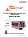
REZNOR
®
USED-OIL-FIRED
HEATERS AND BOILERS
Installation/Operation/Maintenance
Manual and
Reference Guide
CSA Certied to Electrical and Fuel Burning requirements only.
Heater Models
RA 150
RA 250
RAD 150
RAD 250

Form I-RA/RAD 150/250, P/N 234817R7, Page 2
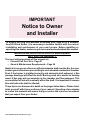
IMPORTANT
Notice to Owner
and Installer
To ensure the long term benets of burning your used oil in a Reznor®
Used-Oil-Fired Heater, it is necessary to become familiar with the correct
installation and maintenance of your new furnace. Before installing or
operating this heater, make sure you have read and understand this manual.
IMPROPER INSTALLATION OR LACK OF MAINTENANCE
WILL VOID THE WARRANTY.
The most critical sections of this manual are
• Correct Draft Over Fire - Page 21
• General Maintenance Requirements - Page 24
Identical to any gas or oil burner, without adequate draft over the re, the com-
bustion gases cannot escape resulting in an overheated combustion chamber.
Even if the burner is installed correctly and adequate draft achieved, a ue
passage blockage will affect the draft. Burning used oil is similar to burning
wood. A ne gray ash accumulates in the chamber and ue passages. This
accumulation of ash will eventually affect the draft. It is important to remove
this ash before the draft is affected.
These topics are discussed in detail on the pages listed above. Please famil-
iarize yourself with these sections of your manual. Spending a few minutes
to review this material will assure that you receive the return on investment
that you expect from your heater.

Form I-RA/RAD 150/250, P/N 234817R7, Page 3
Table of Contents
Installation ....................4-18
Introduction .................................... 4
Use.................................................. 4
Codes and Regulations ................ 4
Warranty ......................................... 4
Safety Warnings ............................ 5
Secondary Heat Source ................ 5
Fuels ............................................... 5
Hazardous Atmosphere ................ 5
Venting ........................................... 5
Air for Combustion ....................... 6
Non-Compliance ............................ 6
Unpacking and Inspection ............ 6
Parts Carton................................... 7
Heater Placement .......................... 8
Minimum Clearances from
Combustibles ................................ 8
High Altitude Installation .............. 9
Fuel Tank, Pump, and
Supply Lines ........................... 10
Fuel Tank ...................................... 10
General Requirements ................ 10
Pump ............................................ 11
Supply Lines Installation ............ 11
Typical Installation ...................... 12
Mounting the Heater .................... 13
Weights ........................................13
Suspension .................................. 13
Venting the Heater ...................... 14
Guidelines for the Vent System . 14
Detailed Vent System
Information ............................15
Draft Regulator ............................16
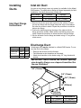
Installing Ducts ............................ 17
Inlet Air Duct ................................ 17
Discharge Duct ............................ 17
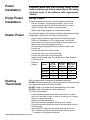
Power Installation ........................ 18
Heater Power ...............................18
Pump Power Installation ............ 18
Heating Thermostat .................... 18
Heater Start-Up ..........19-23
System Check .............................. 19
Priming and Leak Check ............ 19
Heater Start-Up ............................ 21
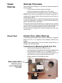
Start-Up Procedure ..................... 21
Check Test - After Start-up ......... 21
Maintenance ...............24-33
General Maintenance
Requirements .......................... 24
Maintenance Schedule ............... 24
Maintenance Procedures ............ 25
Service .......................34-46
General Service ........................... 34
General Operation ....................... 34
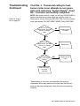
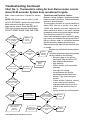
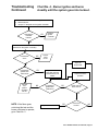
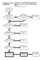
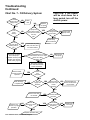
Troubleshooting .......................... 36
Oil Burner Troubleshooting ....... 36
Backow Sensor .........................36
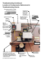
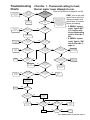
Troubleshooting Chart Guide .... 37
Location of Components
Referenced in Troubleshooting
Charts ..................................... 38
Troubleshooting Charts .............. 39
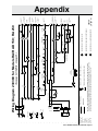
Appendix ....................47-50
Wiring Diagram 230369 for
Models RA/RAD 150;
RA 250
.......................................47
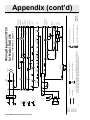
Wiring Diagram 232728 for
Model RAD 250 ...................... 48
Hour Meter / Cleaning Record .... 50
Index ................................51

Form I-RA/RAD 150/250, P/N 234817R7, Page 4
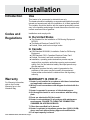
Installation
Use
This heater is for commercial or industrial use only.
The heater should be installed by an experienced installer thoroughly
trained and experienced with the installation of oil-red appliances.
The installer should be familiar with the special precautions neces-
sary in the handling and storage of used automotive oils which may
contain small amounts of gasoline.
Installation must comply with:
In the United States
■ The Standard for the Installation of Oil Burning Equipment
NFPA 31
■ The National Electrical Code NFPA 70
■ Federal, State, and local municipal codes
In Canada
■ CSA Standard B139-M91, Installation Code for Oil Burning
Equipment
■ CSA Standard C22.1-Canadian Electrical Code, Part 1
■ Federal, Provincial, and local municipal codes
■ Installation, operating and maintenance permits may be
required from regulation authorities covering environmental
quality, fuel, re and electrical safety. Municipal permits may
also be required.
■ Regulation requires that only used oil generated on the
premises of the owner may be burned in this equipment
unless written authorization is obtained from the regulatory
authority.
WARRANTY IS VOID IF ....
1. Heater is not installed in accordance with these instructions
and applicable codes and ordinances.
2. Wiring is not in accordance with diagram furnished with the
heater.
3. Heater is operated in presence of chlorinated vapors.
4. Air through the heater is not in accordance with the rating
plate.
5. Ducts are attached to RA (fan) model
6. Heater is not maintained in accordance with maintenance
requirements. FAILURE TO CLEAN THE COMBUSTION
CHAMBER ON A REGULAR BASIS.
7. Other-than-specied fuel is burned.
8. Heater is operated at elevations greater than 3,000 ft (914M)
above sea level without factory approved modications.
9. Fuel input capacity is altered.
Introduction
Codes and
Regulations
Warranty
For Warranty information,
refer to the Limited
Warranty form in the
Literature Bag.

Form I-RA/RAD 150/250, P/N 234817R7, Page 5
Conventions Used in this Manual
Hazard Intensity Levels
DANGER: Failure to comply will result in severe
personal injury or death, and/or property damage.
WARNING: Failure to comply can result in severe
personal injury or death and/or property damage.
CAUTION: Failure to comply could result in minor
personal injury and or personal damage.
NOTE: Additional Warnings are also included throughout this manual.
CAUTION: These heaters are designed to provide
economic disposal of used oils. Used oil is an
inconsistent fuel and may contain water and/or
foreign materials which may cause the unit to
shut down. A secondary source of heat should
always be provided to the building; do not depend
on used oil as your only source of heat. This will
prevent building damage should the heater become
inoperable during subfreezing weather.
WARNING: Approved fuels are No. 2 fuel oil and
used automotive transmission uid and crankcase
oils up to 50 weight. Do not attempt to burn any
grade of gasoline, paint thinner, or non-approved
uids. Adequate ventilation must be provided in
any enclosure where storage tanks, pumps, or
accessories are installed.
This heater is not designed for use in hazardous atmospheres contain-
ing ammable vapors or combustible dust, or atmospheres containing
chlorinated or halogenated hydrocarbons.
WARNING: Failure to provide proper venting
could result in death, serious injury, and/or
property damage. Units must be installed with a
ue connection, draft regulator and proper vent
to the outside of the building. Safe operation of
any gravity vented heating equipment requires a
properly operating vent system, correct provision
for combustion air, and regular maintenance and
inspection.
Safety
Warnings
Secondary
Heat Source
!
Venting
Fuels
Hazardous
Atmosphere

Form I-RA/RAD 150/250, P/N 234817R7, Page 6
Safety Warnings
Continued
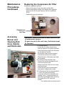
Unpacking
and Inspection
Check the heater for any damage that may have occurred in ship-
ment!
If damage is found, le a claim with the transport company. Your unit
was inspected and tested at the factory prior to crating and was in
perfect condition at that time. Open the boxes and verify receipt of
all parts.
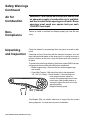
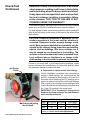
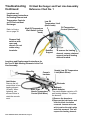
To protect the unit during shipping, the blower model (RAD) has spe-
cial supports that must be removed before installation.
• Blower support legs - Remove the four blower support legs
and screws.
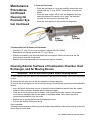
• Check Belt Tension - Belt should be able to be depressed
1/2”- 3/4” (13-19mm) - See illustration. If the belt does not
have proper tension, adjust by
means of the adjusting screw on the
motor base. After proper tension is
achieved, tighten the lock nut on the
adjusting screw.
Replace the belt guard.
WARNING: Care should be exercised to ensure that
an adequate supply of combustion air is available
and free to enter the air openings on all units. Room
openings must equal one square inch per each
1,000 BTU heat input.
Fan Models (RA) use plastic cable ties to support the fan motors
during shipment. Cut and remove prior to installation.
Air for
Combustion
Non-
Compliance
Failure to install or maintain this heater properly will void the war-
ranty.

Form I-RA/RAD 150/250, P/N 234817R7, Page 7
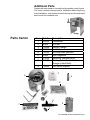
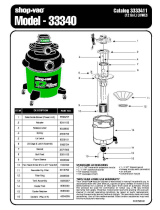
Parts Carton
Item Part No. Description
1 255350 Thermostat
2 96388 Oil Filter
3 135986 Vacuum Gauge
4 110320 Foot Valve
5 130952 Oil Pump Inlet Manifold
6 37866 Draft Regulator
7 121030 Recycling Window Decal
8 121603 Warning label (for inlet to fuel
storage system/tank)
9 136864 Foot Valve Strainer
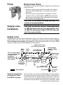
Pump
9
1
6
8
3
5
4
2
7
Additional Parts
Shipped with each heater is a remote fuel pump and a carton of parts.
The carton contains parts required for installation. Before beginning
actual installation, verify that the remote fuel pump and the parts listed
below are at the installation site.

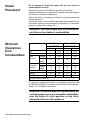
Form I-RA/RAD 150/250, P/N 234817R7, Page 8
Heater
Placement
Do not attempt to install this heater until you have read and
understand this manual!
Placement is critical to the efcient operation of this heater.
Measure all distances to comply with the specic code requirements
and minimum clearances listed below.
Refer to the section on Venting your heater for vent requirements and
recommendations.
Locate the heater so that suitable means shall be provided to facili-
tate regular cleaning and maintenance of the heater (i.e. permanent
platform, portable stairs, ladder, etc.).
WARNING: You must comply with all requirements
on distance from heater to combustibles.
Fan Models Blower Models
RA150/250 RAD150/250
inches mm inches mm
Top 6 152 6 152
Front 48 1219 48 1219
Side
(Burner)*
Canada 6 152 6 152
United
States
18 457 18 457
Side
(Opposite
Burner)*
Canada 6 152 6 152
United
States
18 457 18 457
Rear* 18 457 6 152
Bottom 3 76 3 76
Flue Pipe 9 229 9 229
*Allow for service access.
In Canada, for additional information on installation clearances, refer
to CAN/CSA-B139-M91, “Installation Code for Oil Burning Equipment,”
Clause 7.0 - Installation Clearances.
WARNING: Clearances apply to all combustibles. Do
not leave paper, rags, or any moveable combustibles
near the heater or store gasoline or any other
ammable uid near this appliance.
Minimum
Clearances
from
Combustibles

Form I-RA/RAD 150/250, P/N 234817R7, Page 9
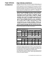
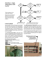
High Altitude Installation
Standard Model RA/RAD 150 and 250 used-oil-red heaters are
designed for use from sea level up to elevations of 3,000 ft. Without
proper modications severe overheating of the combustion chamber
and heat exchanger will occur if installed above 3,000 ft. Also, the on-
board air compressor will not deliver the correct amount of atomizing
air to the fuel nozzle, resulting in poor combustion. Factory-built high
altitude heaters are identied with the sufx “H” (i.e. RA-250-H).
WARNING: Standard model used oil units installed
above 3,000 ft (914M) elevation will overheat,
damaging the heat exchanger assembly. Use of
standard model heater above 5,000 ft (1514M)
elevation may result in incomplete combustion and
formation of carbon monoxide (CO). Elevations
above 3,000 ft (914M) elevation require installation
of a heater that is either factory-built or field
converted for use at high elevation. Failure to
comply can result in severe personal injury or death
and/or property damage and will void the warranty.
Check the rating plate for the approved elevations.
High Altitude
Installation
If the heater is being installed above 3,000 ft, it must either be factory
built (Model 150-H) for that elevation or be changed in the eld. Check
the rating plate for Model and approved elevation. (High altitude kits
for eld conversion are available only for RA/RAD 250.)
The high altitude conversion affects both the remote pump and the
heater. When doing a eld conversion, install the high altitude kit prior
to pump and heater installation.
Models RA/RAD150
Elevation
Fuel Input Heat Input Heat Output
GPH LPH BTUH kw BTUH kw
0-3,000 ft 1.06 4.0 148,000 43.4 118,400 34.7
>3,000 to
7,000 ft
0.8 3.6 112,000 32.8 89,600 26.1
Models RA/RAD250
Elevation
Fuel Input Heat Input Heat Output
GPH LPH BTUH kw BTUH kw
0-3,000 ft 1.78 6.7 250,000 73.3 200,000 58.6
>3,000 to
7,000 ft
1.45 6.6 203,000 59.4 162,400 47.6
>7,000 ft 1.24 5.6 173,600 50.8 138,880 40.7

Form I-RA/RAD 150/250, P/N 234817R7, Page 10
Fuel Tank,
Pump, and
Supply Lines
General Requirements
Model RA/RAD 150 and RA/RAD 250 heaters are approved to burn
used crankcase oil, transmission uid, and No. 2 fuel oil. Maximum
fuel input for a Model 150 is 1.06 GPH (4.0 L/H). Maximum fuel input
for a Model 250 is 1.78 GPH (6.7 L/H).
The oil supply tank and fuel lines must be installed in accordance
with the National Board of Fire Underwriters requirements and all
local ordinances. A UL-listed tank such as Reznor
®
Model OT-250 or
equivalent must be used.
In the U.S., regulations require that storage tanks located inside
buildings shall not exceed 275 gallons (1,041 L) individual capacity
or 550 gallons (2,082 L) aggregate capacity in one building.
In Canada, regulations require storage tanks located inside buildings
shall not exceed 550 gallons (2,082 L) individual capacity or 1,100
gallons (4,164 L) aggregate in one building.
Check with the local Fire Marshall to assure compliance with local
ordinances and codes. Installation of the tank and supply lines is
the responsibility of the installer.
Fuel Tank
CAUTION: It is recommended that used oil be at a
temperature of 50°F or higher when it enters the
pump. At a temperature below 50°F, oil becomes
more viscous and difcult to pump. The heater may
re at a reduced rate and become erratic resulting
in nuisance shutdowns.
Install either a UL listed Reznor
®
Model OT-250 oil supply tank or a
eld-supplied equivalent indoor storage tank.
• If installing a Model OT-250 tank, follow the installation
requirements and instructions on the tank.
• If installing a eld-supplied tank, follow the manufacturer’s
instructions.
• Height from the pump to the bottom of the heater should be
no more than 15 ft (4.5M). The used oil supply line must be
3/8” o.d. and a maximum of 100 ft (30.5M) in length.
Although maximum height from the pump to the heater is 15 ft (4.5 M),
we recommend that ease of service be considered when determining
heater location. A service height of eight feet (2.5 M) is recommended.
See the illustrations on pages 12 and 13 for examples of tank and
line installation.
WARNINGS: Never pour gasoline or used oil
containing gasoline into the supply tank. Adequate
ventilation must be provided in any enclosures
where storage tanks, pumps, or accessories are
installed.
Fuel Tank

Form I-RA/RAD 150/250, P/N 234817R7, Page 11
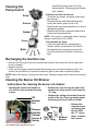
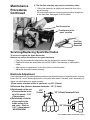
Remote Fuel Pump
The Model OT-250 tank has a platform designed for attaching the
remote fuel pump.
• Attach the fuel pump legs permanently either on the platform,
directly to a eld-supplied tank, or in a location very near to
the oil tank.
• Mount the remote pump assembly in an upright, horizontal
position as shown in the illustration. (NOTE: Motor enclosure
appearance may be different than illustrated but must always
be mounted in this upright position.)
CAUTION: Do not mount the pump assembly in a
vertical or inverted position.
Pump
Supply Lines
Installation
CAUTION: Do not use TEFLON
®
based pipe dope
or TEFLON
®
tape to seal any pipe connections. Use
of TEFLON
®
based pipe dope or TEFLON
®
tape will
void the pump warranty.
Supply Lines
Read this section carefully before installing any supply lines. Since a suction line leak is nearly im-
possible to nd, take your time to assure all connections are leak-free during installation. Supply
lines and ttings are furnished by the installer. See the following illustration for minimum ttings
required. Length of pipe and tubing depends on the installation.
Run the suction line, using 1/2” standard black iron pipe, between
the inlet side of the lter and the foot valve. (Refer to the illustration.)
A fuel line lter with a cleanable strainer, a foot valve, a foot valve
strainer, and a vacuum gauge are provided with the heater. To pre-
vent air from entering the line, do not use union connections. Install
Suction Line (portion
of supply line from
foot valve to pump)

Form I-RA/RAD 150/250, P/N 234817R7, Page 12
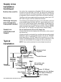
Typical
Installation
Supply Lines
Installation
Continued
the suction line components as illustrated. With the vacuum gauge
mounted on the outlet side of the lter, the gauge will indicate any
suction line restriction including a dirty lter. A pump inlet manifold
is supplied for direct connection of the lter to the inlet of the pump.
The 50 psi relief valve supplied with the pump and a return line of 1/8”
NPT black iron pipe must be installed as illustrated.
The discharge line between the valve on the outlet side of the fuel
pump and the heater should be 3/8” O.D. copper tubing with a mini-
mum of 1/32” wall thickness with 45° are ttings. The discharge line
must continually rise. A lift height of up to 15 ft (4.5 M) is acceptable
with a maximum total length of 100 feet (30.5 M) of tubing. (NOTE:
Do not use 1/2” o.d. tubing in the supply line for these models.)
Do not install manual valves in the supply line.
Connect the fuel line to the heater at the connection on the corner of
the service tray.
All piping should be protected from possible damage and be rigidly
fastened in place in a workmanlike manner. Do not use TEFLON
®
based pipe dope or TEFLON
®
tape at the connections in an oil line.
Use an oil-resistant pipe dope. Do not use union connections in the
suction line (line between the oil supply and the remote pump).
NOTE: Care must be exercised to ensure airtight connections.
Return Line
Discharge Line (por-
tion of supply line
from pump to heater)
Supply Line
Connections and
Support
Suction Line (cont’d)

Form I-RA/RAD 150/250, P/N 234817R7, Page 13
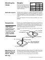
Mounting the
Heater
Weights
Before suspending the unit,
check the supporting structure
to ensure it has sufcient load-
carrying capacity to support the
weight of the heater.
Model
Net Weight
lbs kg
RA150 320 145
RA250 370 168
RAD150 360 163
RAD250 430
195
Use four 1/2”-13 diameter threaded rods. Lock each threaded rod
using a washer and nut as shown in the illustration below. Or, use
optional swivel connections (Option CK10) and eld-provided 1”
threaded pipe. Lock swivel connections as shown in the illustration.
Remove the shipping crate bottom from the unit.
Remove the angle clips and re-insert the screws into the heater
cabinet.
Suspension
WARNING: This
heater must be
supported level for
proper operation.
Do not place or add
additional weight
to the suspended
heater.
Mounting on an
Optional Heater
Stand - Model
RA only
When accompanied with a Reznor Model OT Work Bench Fuel Tank
(OT-250) and an Optional Heater Stand (Option HS-1), a Model RA
150 or 250 heater may be mounted on the heater stand.
Follow the instructions packaged with the optional stand.
Vertical Louvers
Optional vertical louvers are in addition to the standard horizontal
louvers and are designed to direct the discharge air to provide a
wider throw pattern. If vertical louvers (Option CD1) are part of the
installation, install the louvers before lifting the unit to its installation
height.
Follow the illustrated instructions that are included in the louver
package.

Form I-RA/RAD 150/250, P/N 234817R7, Page 14
Venting the
Heater
WARNING: Failure to provide proper venting
could result in death, serious injury, and/or
property damage. Units must be installed with a
ue connection and proper vent to the outside of
the building. Safe operation of any gravity vented
heating equipment requires a properly operating
vent system, correct provision for combustion air,
and regular maintenance and inspection.
The vent system must comply with all local codes and in the event
that local codes do not exist, the vent system must comply with a
regional or national code.
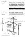
Guidelines
for the Vent
System
The requirements for the vent system are dependent on (1) the loca-
tion of the heater within a building and (2) the type of building.
• If the heater and the vent system are within the same heated
space, single wall pipe may be used inside the building. The
portion of the vent system outside the building must be a
factory-built vent that is approved to Standard UL 641. See
illustration below.

Form I-RA/RAD 150/250, P/N 234817R7, Page 15
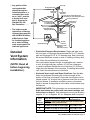
Detailed
Vent System
Information
(NOTE: Read all
before beginning
installation.)
• Any portion of the
vent system that
passes through an
unheated space or a
concealed area such
as an “attic” must be
a factory-built vent
that is approved to
Standard UL 641.
See illustration . . . . .
• The heater may be
vented into a masonry
chimney that complies
with the BOCA Nation-
al Mechanical Code
for low-heat applianc-
es or other building
code requirements for
low-heat appliances.
• Pipe/Joints/Clearance Requirements: Single-wall pipe must
be a minimum of 24 gauge galvanized steel for 8” or 9” diameter
pipe and 22 gauge for 10” or 12” diameter pipe. Each joint must
be secured with three screws or rivets. If installing a factory-built
vent, follow the manufacturer’s instructions.
If the vent system passes through a combustible wall, material
or roof, for single wall pipe, maintain 18” (457mm) clearance
or install a ventilated thimble that is not less than 12” (305mm)
larger than the diameter of the vent pipe. If installing factory-built
vent, follow the manufacturer’s instructions.
• Horizontal Vent Length and Slope Guidelines: See the table
below for guidelines concerning the maximum length of the
portion of vent that is horizontal. Horizontal vent length must be
sloped upward 1/4” for each foot of pipe and must have no more
than two elbows. If installation conditions require a horizontal
length in excess of the guideline in the table, a draft inducer may
be required.
IMPORTANT NOTE: This information is a recommendation only.
Draft must always be veried with instrument readings; see
instructions on page 21.
Draft measurement must read at least a
negative .01” w.c. to negative .02” w.c.
Adequate draft is required.
Vent
Pipe
Diameter
Model Size and Vertical Length
Length of
Horizontal Pipe
Guideline: Vertical vent length should be at least 2 times
the length of the horizontal vent.
8” 150 with 8 ft (2.4M) of vertical pipe 4 ft (1.2M) or less
8” 250 with 8 ft (2.4M) of vertical pipe 4 ft (1.2M) or less
8” 250 with 10 ft (3M) of vertical pipe 5 ft (1.5M) or less

Form I-RA/RAD 150/250, P/N 234817R7, Page 16
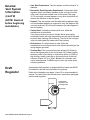
Draft
Regulator
• Vent Size Requirement: The vent system must be at least 8” in
diameter.
• Barometric Draft Regulator Requirement: A barometric draft
regulator which is the same diameter as the vent pipe must be
used, and it should be located close to the heater. See page
16. Do not install a manual damper or any other device that will
obstruct the free ow of the ue gases.
• Support: The vent system must be adequately supported using
non-combustible strapping or supports to carry the weight of the
vent and wind load. Do not use the heater to provide support for
the vent system.
• Vertical Vent: If installing a factory-built vent, follow the
manufacturer’s instructions.
If a masonry chimney is used, a thimble that is permanently
cemented in place with high temperature cement should be used
to permit easy cleaning of the chimney. The end of the vent pipe
must not extend past the inside wall of the chimney.
• Draft Inducer: If a draft inducer is used, follow the
manufacturer’s instructions and wire the inducer according to the
wiring diagram provided.
• Terminal End: The vent must terminate at least 3 ft (914mm)
above the highest point of exit and at least 2 ft (610mm) higher
than any portion of a building or obstruction within 10 ft (3M) of
the chimney. Install a vent cap on the terminal end of the vent.
A Reznor (Option CC1) or Type L Breidert Air-x-hauster
®
vent
cap is recommended. A different style of vent cap could cause
nuisance problems.
A barometric draft regulator is shipped with this heater and MUST
be installed in the ue near the heater ue opening.
Refer to the illustrations on pages 14 and 15 for recommended lo-
cations. To install, follow the manufacturer’s instructions packaged
with the draft regulator.
Detailed
Vent System
Information
(cont’d)
(NOTE: Read all
before beginning
installation.)

Form I-RA/RAD 150/250, P/N 234817R7, Page 17
Installing
Ducts
Inlet Air Duct
An inlet air duct ange (return air system) is available for the Model
RAD heaters. The optional duct ange is shipped separately for eld
installation. Inlet duct dimensions (inside) are:
Duct Flange RAD150 RAD250
Height 26-3/4” (679mm) 26-3/4” (679mm)
Width 24” (610mm) 28” (711mm)
RAD
A Minimum B
150 30” (762mm) 15” (381mm)
250 40” (1016mm) 20” (508mm)
Model RAD 150 250
CFM (free air) 2050 3150
Air throw (9ft
suspension)
55 ft 70 ft
(17M) (21M)
CFM .25" ESP 160 2850
Discharge Duct
A discharge duct may be attached to a Model RAD heater. To con-
nect the duct to the heater,
• Remove the louvers from the furnace.
• Field fabricate a duct transition as illustrated.
• Attach duct transition to the heater using 1/2” long sheetmetal
screws
IMPORTANT: Never reduce the furnace opening
size abruptly. Always use a tapered transition like
the one illustrated.
Inlet Duct Flange
Instructions
1. Remove the screws across the top back of the cabinet. Position
the top duct ange with the ange toward the edge of the cabinet.
Re-insert the screws to attach. Repeat the procedure to install the
bottom duct ange.
2. Position the side ange along the edge of the cabinet with the
ange toward the outside. Attach with the self-drilling screws pro-
vided. Repeat the procedure to attach the other side duct ange.
3. Slip the ductwork over the ange and attach using 1/2” long sheet
metal screws.

Form I-RA/RAD 150/250, P/N 234817R7, Page 18
Heating
Thermostat
Pump Power
Installation
Pump Power
To connect the electrical power from the heater to the pump,
• Use a 3 conductor, 14 gauge wire system - two 115 volt
conductors and a ground. Use BX if permitted, but make
certain to follow local codes for running conduit.
• Refer to the wiring diagram for connecting terminals.
Power
Installation
Heater Power
To install main power to the system (check the table below and the
rating plate on the furnace for current requirements),
• Use #12 gauge stranded copper wire for RA and #8 gauge for
RAD to run a dedicated 115 volt, single phase, line from the
power source to a junction box mounted on the wall behind the
heater or as required by appropriate codes.
• Run the length of appropriate conduit from the heater to the
junction box.
• Connect the black wire to the hot lead.
• Connect the white wire to the neutral lead.
• Connect the green wire to the ground lead.
• Install a fused manual reset, line voltage switch (eld supplied)
in this main line
• Electrical
Ratings
A 24-volt thermostat is furnished as standard equipment.
DO NOT attempt to wire relays or other accessories to the thermostat
connections as these are not load terminals.
DO NOT install on or suspend the thermostat from the heater
DO NOT install thermostat on a cold outside wall
To install the thermostat,
• Locate the thermostat ve feet above the oor on an inside
wall, not in the path of warm or cold air currents nor in corners
where air may be pocketed
• Remove the thermostat cover
• Make sure the heat anticipator dial is set at 0.2 amps
• Connect the wires through the back of the thermostat to the R
& W terminals
• Set the ON/OFF switch on the heater electrical box to the
“OFF” position and connect the thermostat wires to the two
“T” terminals on the ignition controller.
Model
Total
Current
Amperes
Minimum
Circuit
Ampacity
Maximum
Fuse Size
(Supply)
RA150 11 14 20
RAD150 15 18 20
RA250 14 17 30
RAD250 18 23 30
DANGER: Make sure that the main circuit is OFF
before making any wiring connections. All wiring
must be done in accordance with appropriate
Codes!

Form I-RA/RAD 150/250, P/N 234817R7, Page 19
Priming and
Leak Check
For control locations,
refer to illustration on
page 38
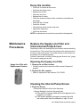
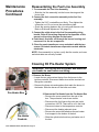
Priming and Checking the System
The oil supply line to the heater must be full of oil and free of air for
proper heater operation.
NOTE: Priming the oil line could take up to 30 minutes depending
on the length of the line.
Follow the procedure below to ll the oil line.
1. Be sure the oil tank is lled to at least six inches above the
top of the foot valve.
Burner
Start-Up
System Check
Check Test - Prior to Start-Up
You should check your system completely before operating it.
Check clearances from combustibles. Be certain that the
clearances are in compliance with the appropriate Codes.
Check hangers and supports. Be certain that all hangers,
supports, and arms are adequately anchored and that all
unions or threaded ttings are snug and do not rotate.
Heater must be level.
Check to make sure all shipping supports have been
removed.
Check the electrical supply. Be sure that all wire gauges are
as recommended and that the supply voltage is as stated
on the heater. Determine that fusing or circuit breakers are
adequate for the load.
Check vents. Be sure that vent pipe and chimney meet
the requirements and appropriate codes. A UL or CSA/UL
listed draft regulator is required. A Reznor
®
(Option CC1) or
Type L Breidert Air-X-hauster
®
vent cap is recommended.
(Type L Air-X-hauster
®
is a trademark of The G. C. Breidert
Company.)
Check the oil supply. Fill the supply tank to at least six inches
from the top of the foot valve. NOTE: Always screen used oil
with a 70-80 mesh strainer when lling the supply tank.
Canadian RAD (blower model) installation only -- Be sure an
inlet air duct is installed in compliance with Codes.
Heater Start-Up

Form I-RA/RAD 150/250, P/N 234817R7, Page 20
2. Set manual disconnect switch to the ON position.
3. Fill the suction line (line between the supply tank and the
pump) with clean used oil. (Do not use new motor oil.)
4. Locate the rubber tubing connecting the pressure switch in
the main control box and the compressor.
• Disconnect the tubing at the tting on the compressor. This will
prevent oil from owing to the burner.
5. Remove the cad-cell wire from the F1-F2 terminals of the
ignition controller.
• Either attach a piece of tubing to the bleeder valve on the
strainer tee (see page 26) on the burner assembly or place a
container underneath to collect oil.
• Loosen the bleeder valve.
6. Set the thermostat to a temperature above room temperature.
NOTE: On initial start-up it will take approximately ten minutes to
heat the oil. Once the oil is warm enough, the green light will come
on and the unit will be ready to start. This delay only occurs on initial
start-up or when the disconnect switch has been turned off for an
extended time.
• After the motor starts, place a jumper across the cad-cell
terminals (F1-F2) on the ignition controller.
• Observe the remote fuel pump motor to make certain it is
running.
• Open the bleeder valve on the remote pump and wait until a
full ow of oil is obtained without any air.
IMPORTANT NOTE: If air bubbles are present and do not stop, there
is a suction line leak.
• Check the piping between the tank and the pump and correct
the leak.
• Once a full ow of oil is present without any sign of air, close
the bleeder valve on the remote pump.
• Observe the bleeder valve at the strainer tee and wait until a
full ow of oil is obtained without any air.
• Tighten the bleeder valve on the strainer tee and remove the
oil container.
NOTE: DO NOT replace the rubber tubing previously disconnected
from the compressor and DO NOT re-connect the cad-cell wires.
7. Allow the system to operate for several minutes.
• Check the system for leaks at all connections.
• Observe the return line to the tank - oil should be owing.
• Correct all leaks and re-test the system.
8. When the system checks out as having no leaks, turn
disconnect OFF, replace the rubber tubing and cad-cell wires
removed earlier.
9. Remove the jumper from the F1-F2 terminals of the ignition
controller.
Priming and
Leak Check
Continued
For control locations,
refer to illustration on
page 38
You are now ready to start your system.
Page is loading ...
Page is loading ...
Page is loading ...
Page is loading ...
Page is loading ...
Page is loading ...
Page is loading ...
Page is loading ...
Page is loading ...
Page is loading ...
Page is loading ...
Page is loading ...
Page is loading ...
Page is loading ...
Page is loading ...
Page is loading ...
Page is loading ...
Page is loading ...
Page is loading ...
Page is loading ...
Page is loading ...
Page is loading ...
Page is loading ...
Page is loading ...
Page is loading ...
Page is loading ...
Page is loading ...
Page is loading ...
Page is loading ...
Page is loading ...
Page is loading ...
Page is loading ...
-
 1
1
-
 2
2
-
 3
3
-
 4
4
-
 5
5
-
 6
6
-
 7
7
-
 8
8
-
 9
9
-
 10
10
-
 11
11
-
 12
12
-
 13
13
-
 14
14
-
 15
15
-
 16
16
-
 17
17
-
 18
18
-
 19
19
-
 20
20
-
 21
21
-
 22
22
-
 23
23
-
 24
24
-
 25
25
-
 26
26
-
 27
27
-
 28
28
-
 29
29
-
 30
30
-
 31
31
-
 32
32
-
 33
33
-
 34
34
-
 35
35
-
 36
36
-
 37
37
-
 38
38
-
 39
39
-
 40
40
-
 41
41
-
 42
42
-
 43
43
-
 44
44
-
 45
45
-
 46
46
-
 47
47
-
 48
48
-
 49
49
-
 50
50
-
 51
51
-
 52
52


Reznor RA/RAD Small Installation guide
- Category
- Space heaters
- Type
- Installation guide
Ask a question and I''ll find the answer in the document
Finding information in a document is now easier with AI
Related papers
Other documents
-
Broan H6HK, 15 Kw 240V,1-Phase Electric Heater Kit Product information
-
Summit ADAH1618SS Owner's manual
-
-
 Shop Vac 33340 Owner's manual
-
 MorrHeat MH480B User manual
-
Desa Tech DBV250C Owner's manual
-
-
Omni OWH-500 User guide
-
Lennox International Inc. OSR20 User manual
-
George Kovacs GKTF01-084 User manual

