Page is loading ...

DESIGN, INSTALLATION AND
SERVICING INSTRUCTIONS
ALL MODELS COMPLY WITH THE
WATER HEATER MANUFACTURERS
SPECIFICATION FOR THERMAL STORES
PULSACOIL
2000
PULSACOIL
2000
TM
benchmark
The code of practice for the installation,
commissioning & servicing of central heating systems
A MAINS PRESSURE HOT WATER SUPPLY
SYSTEM INCORPORATING AN OFF PEAK
ELECTRIC THERMAL STORE
Gas Council Approved Reference Numbers
PulsaCoil 145 97-317-32
PulsaCoil 185 97-317-33
PulsaCoil 215 97-317-34
PulsaCoil 235 97-317-35

Page 2
CONTENTS
Section Page
1.0 DESIGN
1.1 Introduction 3
1.2 Technical Data 5
1.3 System Details 9
2.0 INSTALLATION
2.1 Site Requirements 13
2.2 Installation 14
2.3 Commissioning 18
3.0 SERVICING
3.1 Annual Servicing 20
3.2 Changing Components 20
3.3 Short Parts List 21
3.4 Fault Finding 22
Appendix A 24
Appendix B 25
Appendix C 28
Appendix D 29
Terms & Conditions 30
The Gledhill PulsaCoil range is a WBS
listed product and complies with the WMA
Specification for hot water only thermal
storage products. The principle was
developed originally in conjunction with
British Gas. This product is manufactured
under an ISO 9001:2000 Quality System
audited by BSI.
The Gledhill Group’s fi rst priority is to give a
high quality service to our customers.
Quality is built into every Gledhill product
and we hope you get satisfactory service
from Gledhill.
If not please let us know.
ISSUE 11: 06-08
As part of the industry wide “Benchmark” Initiative all Gledhill PulsaCoils now include
a Benchmark Installation, Commissioning and Service Record Log Book. Please
read carefully and complete all sections relevant to the appliance installation. The
details of the Log Book will be required in the event of any warranty work being
required. There is also a section to be completed after each regular service visit.
The completed Log Book and these instructions should be left in the pocket
provided on the back of the front panel.
TM
benchmark
The code of practice for the installation,
commissioning & servicing of central heating systems

Page 3
PULSACOIL
2000
1.0 DESIGN
1.1 INTRODUCTION
Any water distribution system/installation must
comply with the relevant recommendations
of the current version of the Regulations and
British Standards listed below:-
Building Regulations
Requirements for Electrical Installations
Water Regulations
Manual Handling Operations Regulations
British Standards
BS6700 and BS7671.
A competent person must install the PulsaCoil
domestic hot water system. The manufacturer’s
notes must not be taken as overriding statutory
obligations.
The PulsaCoil 2000 is not covered by section
G3 of the current Building Regulations and is
therefore not notifi able to Building Control.
The information in this manual is provided to
assist generally in the selection of equipment.
The responsibility for the selection and
specifi cation of the equipment must however
remain that of the customer and any Designers
or Consultants concerned with the design and
installation.
Please Note: We do not therefore accept any
responsibility for matters of design, selection
or specifi cation or for the effectiveness of an
installation containing one of our products
unless we have been specifically requested
to do so.
All goods are sold subject to our Conditions
of Sale, which are set out at the rear of this
manual.
In the interest of continuously improving
the PulsaCoil range, Gledhill Water Storage
Ltd reserve the right to modify the product
without notice, and in these circumstances
this document, which is accurate at the time
of printing, should be disregarded. It will
however be updated as soon as possible after
the change has occurred.

Page 4
Cold Feed
Open Vent
Test
Pocket
DHW
Primary Pump
Remote F & E
Cistern
Warning/
Overflow
On-Peak
immersion
and control overheat
thermostat
Off-Peak
immersion and control
overheat thermostat
Plate Heat
Exchanger
DHW Sensor
PHE Sensor
Drain
Connection
Domestic
H/W Out
Mains
Cold In
Strainer
and flow
regulator
Expansion
Chamber
SCHEMATIC HYDRAULIC ARRANGEMENT
Components fitted within
Appliance case
*
*
Ballvalve
The PulsaCoil 2000 shown schematically above is designed to provide an improved
method of supplying mains pressure hot water when used with a suitable off peak
electric supply/tariff.
Because of the effi ciency of the appliance improved SAP ratings can be achieved. Further
details are available from the Gledhill Technical Department.
An important feature of the concept is that hot water can be supplied directly from the
mains at conventional fl ow rates without the need for temperature and pressure relief
safety valves or expansion vessels. This is achieved by passing the mains water through a
plate heat exchanger. The outlet temperature of the domestic hot water is maintained by
the Pump Speed Control (P.S.C.) board, which controls the speed of the pump circulating
the primary water from the store through the plate heat exchanger.
To comply with the Benchmark Guidance Note for Water Treatment in heating and hot
water systems the installer should check the hardness levels of the water supply and if
necessary fi t an in-line scale inhibitor/reducer to provide protection to the whole of the
domestic water system.
If scale should ever become a problem the plate heat exchanger is easily isolated and
quickly replaced with a service exchange unit which can be obtained at a nominal cost
from Gledhill. For further details see Hot and Cold Water Systems, page 9.
1.0 DESIGN
Description
1.1 INTRODUCTION
The PSC incorporates the facility to
automatically run the D.H.W. primary pump
for about 3 seconds every 30 hours to help
prevent it sticking. For this reason we would
recommend that once the appliance is
installed it should be commissioned and
the electricity left on to the appliance.
* Note: The standard appliance is
supplied as a manual fill model i.e.
without a ballvalve and overfl ow which
makes it particularly suitable for use
in flats/apartments. A ballvalve and
overflow fitting can be supplied as an
optional extra if required.

Page 5
PULSACOIL
2000
egnaRledoMweN 541CP 581CP 512CP 532CP
thgieWecnailppA
-ytpmE-
-lluF-
)gK(26861747
)gK(202832162492
detaehretawfoemuloV
)retaehkaep-no(
)sertil(56560757
ep
iPWHD&WCM
snoitcennoc
)mm(22222222
noisnapxe/deefdloC
noitcennoc
)mm(51515151
tnevnepoytefaS
noitcennoc
)mm(22222222
noitc
ennocniarD"2/1R"2/1R"2/1R"2/1R
daehmumixaM)m(01010101
etarwolfretawtoH)nim/stl(53otpu53otpu53otpu53otpu
EDIUGNOITCELESLEDOM
epyTgnillewD
moordeB2-13-23-24-2
smoorhtaB
1
ro
1
112
smoorrewohsetiuS-nE121
ffirat7ymonocEdradnatS541CP581CP512CP532CP
ffi
ratesiwtaeHro01ymonocE541CP541CP541CP581CP
1.2 TECHNICAL DATA
1.0 DESIGN
Notes:-
1. Plastic feed and expansion cistern will be supplied separately.
2. The fl ow rates are based on a 35°C temperature rise and assume normal pressure and adequate fl ow to the appliance. The actual
fl ow rate from the appliance is automatically regulated to a maximum of 28 litres/min.
3. Unit is supplied on a 100mm high installation base.
4. The domestic hot water outlet temperature is automatically regulated to approximately 55°C at the bath fl ow rate of 18 litres/min
recommended by BS 6700. The temperature is not user adjustable.

Page 6
1.2 TECHNICAL DATA
Standard Equipment
The standard confi guration of the PulsaCoil
2000 is shown opposite. The Pump Speed
Control Board (P.S.C.), mounted inside
the appliance, controls the operation of
the complete system. The P.S.C. is pre-
wired to a terminal strip where all electrical
connections terminate. It is supplied with
the following factory fi tted equipment:-
1. 3kW off-peak immersion heater with
control and overheat rod thermostat
2. 3kW on-peak boost immersion
heater with control and overheat rod
thermostat
3. Pump Speed Control Board (P.S.C.)
4. Plate heat exchanger
5. Domestic hot water primary (plate
heat exchanger) pump
6. Isolating terminal connectors for dry
fi re protection
7. DHW temperature sensor
8. PHE return sensor
9. Strainer and fl ow regulator
10. Screwed connection for a drain tap
11. A feed and expansion cistern complete
with cold feed/open vent pipework
assembly is supplied separately.
Note : Both immersion heaters are low
watts density type with incaloy 825 sheaths
and are specially manufactured to suit
Thermal Stores. It is recommended that
any replacements should be obtained from
Gledhill Water Storage.
Optional Extra Equipment
• Flexible connectors for quick
connection to fi rst fi x pipe installation.
For further details see 2.2 Installation,
Pipework connections.
• Hot and cold water manifolds for use
with plastic pipework.
• Ballvalve/overfl ow connector for
F & E cistern
1.0 DESIGN
Pump Speed
Control Board
P.S.C
6
1
2
11
3
4
5
9
10
7
8

Page 7
PULSACOIL
2000
B
E
600mm min clear opening - if
located directly in front of the
appliance.
Maintenance
access
Min maintenance
access to comply with
the Water Regulations
(ballvalve model only)
CUPBOARD
F
C
300mm
420mm
280mm
600mm
100mm
*350mm
D
A
F & E Cistern
F & E Cistern
plan
1.0 DESIGN
1.2 TECHNICAL DATA
Note: The Appliance dimensions above do not allow for
the100mm high installation base
The following table of minimum cupboard dimensions only
allow the minimum space required for the appliance (including
the F & E cistern). Any extra space required for shelving etc in
the case of airing cupboards etc must be added.
SNOISNEMIDECNAILPPA
ledoM
thgieH htdiW htpeD
ABC
541CPmm0411mm595mm575
581CPmm0631mm595mm575
512CPmm0051mm595mm575
532CPmm0071mm595mm575
Note: The above dimensions are based on the Appliance
and the F & E cistern (fi tted with a ballvalve) being in the
same cupboard. If the manual fi ll method is chosen the
heights can be reduced by 125mm.
MINIMUM CUPBOARD DIMENSIONS
Model
Height Width Depth
DEF
PC 145 1890mm 700mm 600mm
PC 185 2110mm 700mm 600mm
PC 215 2250mm 700mm 600mm
PC 235 2450mm 700mm 600mm

Page 8
Cut out area through
base of unit - showing
recommended pipework
riser positions.
Note: If the pipework/electrical supply is
dropping from high level use the holes/
grommets provided in the right hand side
panel as shown below
595
575
REAR
PLAN OF APPLIANCE CONNECTIONS
445
70
160
425
Safety/Open Vent
Cold feed/Expansion
REMOVABLE FRONT ACCESS PANEL
TOP
The PulsaCoil 2000 units are supplied on an installation base to allow the pipe
runs to connect to the appliance from any direction. It is easier if all pipes
protrude vertically in the cut out area shown. Compression or push fit
connections can be used and we do offer a set of flexible connectors as an
option. All pipe positions are approximate and subject to a tolerance of +/-
10mm in any direction. Space will also be required for a 15mm cold water
supply and a 22mm warning / overflow pipe (if provided) for the separate feed
and expansion cistern.
If a warning/overflow pipe is NOT provided the F&E Cistern should be filled
from a temporary hose connection incorporating a double check valve. This
can be from a temporary hose connection supplied from a cold water tap or a
permanent cold branch provided adjacent to the F&E Cistern. The temporary
connection must be removed once the appliance is filled.
Domestic Hot Supply
Part view of RH side panel
Cold main supply
Domestic hot supply
Elec supply
Cold Mains Supply
515
540
45
70
405
325
80
130
160
1.0 DESIGN
1.2 TECHNICAL DATA

Page 9
PULSACOIL
2000
Pressure limiting valve NOT
REQUIRED at pressures
below 5 bar unless any
components have a lower
maximum working pressure.
Second
dwelling
M.C.W.S
supply pipe.
Sink
Open vent
Warning/overflow
pipe
Cold feed/
expansion
Hand
basin
WC -
fitted with
BS1212 ballvalve
Bath
PC 2000
Scale inhibitor
NOT REQUIRED
Shower.
H
aa
a
a
aa a
S.V.
C
HC HC C
Check valve NOT REQUIRED unless
chemical water treatment unit is fitted.
'a'
- flow regulator recommended for better
balance of hot and cold water supplies.
Double check valve NOT REQUIRED unless supply
pipe services more than one dwelling.
Typical hot and cold water distribution
F&E Cistern
Cold mains
supply
1.3 SYSTEM DETAILS
Hot and Cold Water System
General
A schematic layout of the hot and cold water services in a typical small dwelling is
shown below. PulsaCoil 2000 will operate at mains pressures as low as 1 bar and as
high as 5 bar although the recommended range is 2-3 bar dynamic at the appliance.
If the manifolds (available as an optional extra) are being used the inlet pressure to
the manifold must be a minimum of 2 bar. It is also important to check that all other
equipment and components in the hot and cold water system are capable of accepting
the mains pressure available to the property. If the mains pressure can rise above 5
bar or the maximum working pressure of any item of equipment or component to be
fi tted in the system, a pressure limiting (reducing) valve set to 3 bar will be required.
If you encounter a situation where the water pressure is adequate but fl ow rates are
poor please contact our technical helpline for details of an effective solution.
Note : Each Pulsacoil 2000 is fi tted with a strainer and fl ow regulator on the cold
mains supply connection. If the supply pressure is less than 2 bar or if the manifolds
(available as an optional extra) are being used or if all taps are provided with fl ow
regulators the fl ow regulator on the cold inlet should be removed.
No check valve or similar device should be fi tted on the cold water supply branch
to the PulsaCoil 2000.
To comply with the Benchmark Guidance Note for Water Treatment in Heating and Hot
Water Systems the installer should check the hardness level of the water supply and
if necessary fi t an in-line scale inhibitor/reducer to provide protection to the whole
of the domestic water system. See Appendix C for a copy of the relevant part of the
Benchmark Guidance Note.
1.0 DESIGN
When specifying this appliance we would
recommend that for hardness levels above
200ppm (mg/l) a hard water appliance is used.
For hardness levels above 250ppm( mg/l) we
would recommend that some form of in-line
scale inhibitor/reducer recommended by one
of the water treatment companies listed in the
Benchmark Guidance Note is also fi tted
The hot water fl ow rate from the PulsaCoil
2000 is directly related to the adequacy of the
cold water supply to the dwelling. This must
be capable of providing for those services,
which could be required to be supplied
simultaneously, and this maximum demand
should be calculated using procedures defi ned
in BS 6700.
If a water meter is fi tted in the service pipe,
it should have a nominal rating to match the
maximum hot and cold water peak demands
calculated in accordance with BS 6700. This
could be up to 60ltr/min in some properties.
Note:
The diagram below shows the F & E
cistern
with ballvalve and warning/overflow pipe
which can be fi tted if required. However, the
standard preferred arrangement is for the
cistern to be manually fi lled from a temporary
hose connection fi tted with a double check
valve.

Page 10
1.3 SYSTEM DETAILS
Hot and Cold Water System
Pipe Sizing / Materials
To achieve even distribution of the available supply of hot and cold water, it is
important in any mains pressure system, that the piping in a dwelling should be sized
in accordance with BS 6700. This is particularly important in a large property with
more than one bathroom.
However, the following rule of thumb guide lines should be adequate for most smaller
property types as long as water pressures are within the recommended range.
1. A 15mm copper or equivalent external service may be sufficient for a
small 1bathroom dwelling (depending upon the flow rate available), but
the minimum recommended size for new dwellings is 22mm (25mm MDPE).
2. The internal cold feed from the main incoming stop tap to the PulsaCoil
should be run in 22mm pipe. The cold main and hot draw-off should also
be run in 22mm as far as the branch to the bath tap.
3. The final branches to the hand basins and sinks should be in 10mm and to
the baths and showers in 15mm. (1 metre minimum)
4. We would recommend that best results for a balanced system are achieved by
fi tting appropriate fl ow regulators to each hot and cold outlet. This is particularly
relevant where the water pressures are above the recommended water pressure
range. Details of suitable fl ow regulators are provided in Appendix A.
Note: If manifolds (available as an optional extra) are being used suitable fl ow
regulators are automatically provided in the manifold and do not need to be
provided at each outlet. See Appendix B for further details.
All the recommendations with regard to pipework systems in this manual are generally
based on the use of BS/EN Standard copper pipework and fi ttings.
However, we are happy that plastic pipework systems can be used in place of copper
internally as long as the chosen system is recommended for use on domestic hot
and cold water systems by the manufacturer and is installed fully in accordance with
their recommendations.
This is particularly important in relation to use of push fi t connections when using the
optional fl exible hose kits - see 2.2 Installation, Pipework connections.
It is also essential that if an alternative pipework material/system is chosen the
manufacturer confi rms that the design criteria of the new system is at least equivalent
to the use of BS/EN Standard copper pipework and fi ttings.
Taps/Shower Fittings
Aerated taps are recommended to prevent splashing.
Any type of shower mixing valve can be used as long as both the hot and cold
supplies are mains fed. However all mains pressure systems are subject to dynamic
changes particularly when other hot and cold taps/showers are opened and closed,
which will cause changes in the water temperature at mixed water outlets such
as showers. For this reason and because these are now no more expensive than
a manual shower we strongly recommend the use of thermostatic showers with
this appliance.
The shower head provided must also be suitable for mains pressure supplies.
However, if it is proposed to use a ‘whole body’ or similar shower with a number of high
fl ow/pressure outlets please discuss with the Gledhill technical department.
1.0 DESIGN
The hot water supply to a shower-mixing
valve should be fed wherever practical
directly from the PulsaCoil 2000 or be the
fi rst draw-off point on the hot circuit. The
cold supply to a shower-mixing valve should
wherever practical be fed directly from the
rising mains via an independent branch.
The shower must incorporate or be fi tted
with the necessary check valves to provide
back-syphonage protection in accordance
with the Water Regulations.
The supply of hot and cold mains water
directly to a bidet is permitted provided
that it is of the over-rim fl ushing type and
that a type ‘A’ air gap is incorporated.
Hot and Cold Water System
If the length of the hot water draw off
pipework is excessive and the delivery time
will be more than 60 seconds before hot
water is available at the tap, you may wish
to consider using trace heating to the hot
water pipework such as the Raychem HWAT
system. Please consult Gledhill Technical
Department for further details.
Note: A conventional pumped secondary
circulation system is NOT suitable for use
with this appliance.
It is important that the cold water pipework
is adequately separated/protected from
any heating/hot water pipework to ensure
that the water remains cold and of drinking
water quality.

C2
C1
PSC
DHW Sensor
PHE Sensor
DHW
Pump
L
N
E
L
N
E
L
N
E
230V, 50Hz
3A
Control Circuit
Supply
ON PEAK
230V, 50Hz
15A
OFF PEAK
230V, 50Hz
15A
Immersion
(Off Peak)
Immersion
(On Peak)
Green Lamp
Com
p
lete with control and safet
y
thermostats
C1 and C2 : Isolating terminals for
dry firing protection
Page 11
PULSACOIL
2000
1.0 DESIGN
1.3 SYSTEM DETAILS
Electrical Installation
The Schematic arrangement of the wiring
within the PulsaCoil 2000 is shown above.
The whole of the electrical installation shall
be designed and installed by a competent
person fully in accordance with the latest
edition of the Requirements for Electrical
installations BS 7671.
The PulsaCoil 2000 appliance is provided with
two side entry 3kW immersion heaters and
has been designed to generally operate with
an off peak supply.
The lower immersion heater heats the whole
of the contents and is normally connected to
the off peak supply.
PulsaCoil 2000 Schematic Wiring Diagram

Page 12
1.0 DESIGN
1.3 SYSTEM DETAILS
Electrical Installation
The upper immersion heater is positioned at a level on the PulsaCoil 2000 to provide
suffi cient hot water for at least one bath - see Technical Data Table on page 5. This
is connected to the unrestricted on peak supply and is normally switched manually
by the householder to provide a day time boost when required. Alternatively a time
clock could be wired into this supply to provide an automatic boost on a daily basis
if preferred.
The size of the appliance and the need to use the on peak boost facility is reduced if
a better off peak tariff can be agreed with the electrical supply company - see Model
Selection Guide on page 5.
A 3 amp supply is also required from the unrestricted on peak supply for the control
circuit.
Although the PulsaCoil 2000 appliance is primarily designed to operate with an off peak
supply it will also operate quite successfully if it is only supplied with an on peak supply.
However, this will substantially increase the running costs of the appliance and should
only be considered if an off peak supply is not available.
Note:
In addition to the supplies to the
immersion heaters, PulsaCoil 2000
requires a 3 amp supply for the control
circuit. This 3 amp supply must be
provided via a fused 3 amp double pole
isolator providing 3mm of separation
to both poles.
To upper (boost)
element
To lower (off peak)
element
To control circuit
Boost
Switch
Off Peak
Controller
20A double pole switch with neon
3A double pole switch
Unrestricted on peak and timed
off peak supply
(from Electricity Supply Company Meter)
Typical arrangement
using an off peak
controller
20A double pole switch with flex outlet
and neon (or timer incorporating double
pole switch)
3A Double Pole switch
to control circuit
To upper (boost) element
Storage Heaters
Unrestricted on peak supply
(from Electricity Supply Company Meter)
Restricted time off peak supply
(from Electricity Supply Company
timeswitch/meter)
To lower (off peak) element
20A double pole switch with flex outlet
and neon
Typical arrangement using two separate
electrical circuits
Two typical methods of providing electrical
supplies are shown below for information.
However, the PulsaCoil 2000 appliance is
suitable for use with any method of supply
- if unsure please consult Gledhill Technical
Department for further assistance.
If separate circuits are provided the two
switches must be clearly labelled for the
householders use.

Page 13
PULSACOIL
2000
2.0 INSTALLATION
2.1 SITE REQUIREMENTS
The appliance is designed to be installed in an airing/cylinder cupboard and the
relevant minimum dimensions are provided in section 1.2 Technical Data.
Because of the ease of installation we recommend that the cupboard construction
is completed and painted before installation of the appliance. The cupboard door
can be fi tted after installation.
If the unit needs to be stored prior to installation it should be stored upright in a dry
environment and on a level base/fl oor.
Installation and maintenance access is needed to the front of the appliance and
above the F & E cistern. See Section 1.2 Technical Data for further details.
The minimum dimensions contained in section 1.2 Technical Data allow for the
passage/connection of pipes to the appliance from any direction as long as the
appliance is installed on the installation base provided. If the installation base is not
used extra space may be needed to allow connection to the pipework and the whole
of the base area should be continuously supported on a material which will not easily
deteriorate if exposed to moisture.
The fl oor of the cupboard needs to be level and even and capable of supporting
the weight of the appliance when full. Details of the weight when full is provided
in section 1.2 Technical Data.
The appliance is designed to operate as quietly as practicable. However, some noise
(from pumps etc) is inevitable when hot water is being used. This will be most
noticeable if the cupboards are located adjacent to bedrooms, on bulkheads, or at
the mid span of a suspended fl oor.
Cupboard temperatures will normally be higher than in a conventional system and
the design of the cupboard and door will need to take this into account. No ventilation
is normally required to the cupboard.
The separate feed and expansion cistern will need to be located on top of the
appliance or at high level in the cupboard housing the PulsaCoil 2000. The dimensions
and clearances are provided in section 1.2 Technical Data. The location will need to
provide a suitable route for the cold feed and expansion pipe as well as the open
safety vent pipe. The location will also need to provide a suitable route and discharge
position for the warning/overfl ow pipe and the ballvalve supply from the mains cold
water system (if provided).
Note: The standard appliance is supplied with a cistern without a ballvalve/
overfl ow for fi lling manually.
An electrical supply must be available which is correctly earthed, polarized and in
accordance with the latest edition of the IEE requirements for electrical Installations
BS 7671.
The electrical mains supply needs to be 230V/50Hz.
The sizes/types of electrical supplies must be as detailed in 1.3 System Details,
Electrical Installation and the connections must be made using a double-pole linked
isolator with a contact separation of 3mm in both poles which are located within 1m
of the appliance. The supplies must only serve the appliance.
The hot and cold water ‘fi rst fi x’ pipework should be terminated 50mm above the
fi nished fl oor level in accordance with the dimensions provided in 1.2 Technical
Data.

Page 14
2.2 INSTALLATION
2.0 INSTALLATION
HANDLING
When lifting the unit work with someone of similar build
and height if possible.
Choose one person to call the signals.
Lift from the hips at the same time, then raise the unit to
the desired level.
Move smoothly in unison.
Larger units may require a team lift.
A specifi c manual handling assessment is shown in
Appendix D at the rear of this manual.
Preparation/placing the appliance in position.
The ‘fi rst fi x’ pipework positions should be checked using the template provided with
each appliance. If these have been followed installation is very simple and much
quicker than any other system.
The appliance is supplied shrink wrapped on a timber installation base. Carrying
handles are also provided in the back of the casing.
The feed and expansion cistern complete with ballvalve, cold feed/expansion and
overfl ow/warning pipe fi ttings are provided in a separate box.
If fl exible connections have been ordered these will also be inside the feed and expansion
cistern.
The appliance should be handled carefully to avoid damage and the recommended
method is shown above.
Note: Although the above guidance is provided any manual handling/lifting operations
will need to comply with the requirements of the Manual Handling Operations
Regulations issued by the H.S.E.
The appliance can be moved using a sack truck on the rear face although care should
be taken and the route should be even.
In apartment buildings containing a number of storeys we would recommend that the
appliances are moved vertically in a mechanical lift.
If it is proposed to use a crane expert advice should be obtained regarding the need
for slings, lifting beams etc.
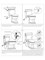
Before installation the site requirements
should be checked and confirmed as
acceptable.
The plastic cover and protective wrapping
should be removed from the appliance and
the installation base (provided) placed in
position.
The appliance can then be lifted into
position in the cupboard on top of the base
and the front panel removed by unscrewing
the 2 screws and lifting the door up and out,
ready for connection of the pipework and
electrical supplies.
The feed and expansion cistern support
shall be installed ensuring that the base
is fully supported, the working head
of the appliance is not exceeded and
the recommended access is provided for
maintenance - see section 1.2 Technical Data
for details.

Page 15
PULSACOIL
2000
C
B
A
D
E
The position of the pipework connections is
shown opposite. The connection sizes and
dimensions are listed in Section 1.2 Technical
Data.
All the connections are also labelled on the
appliance. It is essential that the pipework is
connected to the correct connection.
The connections can be hard piped but we
recommend the use of fl exible connections
(available as an optional extra).
If using push fi t connectors with the fl exible
hose kits it is important to check that they
are compatible. Written approval has already
been obtained for:-
Hepworth - Hep
2
O BiTite
John Guest - Speedfi t
Yorkshire - Tectite
However, as similar assurances cannot be
obtained for Polypipe fittings we cannot
recommend their use.
Connections A, B and D are plain ended
copper pipe.
Connection C is a compression fi tting.
Connection E is RC½ (½ in BSPT internal)
A - Safety open vent
B - Cold feed/expansion
C - Incoming mains cold water
D - Domestic hot water
E - Drain tap connection
2.0 INSTALLATION
2.2 INSTALLATION
Pipework connections
Note: The safety open vent and cold feed/
expansion should be connected to the
F & E cistern using the pipework assembly
provided.
All factory made joints should be checked
after installation in case they have been
loosened during transit.
The fi ttings for the feed and expansion cistern
should be installed following the instructions
provided by the manufacturer in a position
to suit the particular location and the cistern
fi tted on its supports/base.
The cold feed/expansion and safety open vent
should be installed between the appliance
and the feed and expansion cistern.

Page 16
Cold feed / open vent
pipework assembly
(as supplied)
Interconnecting
Pipework
(By Installer)
2.2 INSTALLATION
2.0 INSTALLATION
It is normally envisaged that the feed and
expansion cistern will be located in the same
cupboard as the PulsaCoil 2000 appliance
itself to maintain a dry roof space.
The cold feed/open vent pipework assembly
(as supplied) should be used if it is intended
to install the F & E cistern directly on top
of the appliance.
However, if it is necessary to locate the
cistern in the roof space (or on a higher
floor) the cold feed/open vent pipework
assembly (as supplied) should be used to
connect to the F & E cistern and pipework
site run by the installler to connect this to
the appliance.
Obviously, any pipework in the roof space
and the feed and expansion cistern will
need to be adequately insulated to protect
against frost damage.
Combined feed and open vent pipe
arrangements must not be used.
No valves should be fitted in the safety
open vent which must be a minimum of
22mm copper pipe or equivalent.
The mains cold water supply to the ballvalve
shall be provided with a suitable servicing
valve.
The overflow/warning pipe (if provided)
shall have a continuous fall, be fitted to
discharge clear of the building and be
sited so that any overflow can be easily
observed. It shall also be installed in a size
and material suitable for use with heating
feed and expansion cisterns in accordance
with BS 5449 (e.g 22mm copper) and should
not have any other connections to it.
Note: If a warning/overfl ow pipe is NOT
provided the F & E cistern should be
fi lled from a temporary hose connection
supplied from any cold water tap or
from a permanent cold branch provided
adjacent to the F & E cistern. The
temporary hose must be fitted with a
double check valve and removed once
the appliance is fi lled.

Page 17
PULSACOIL
2000
WIRING DIAGRAM - STANDARD PULSACOIL
2000
APPLIANCE
2.0 INSTALLATION
2.2 INSTALLATION
Br
G/Y
Bl
R Bl G/Y
Br
Bl
YY
Y
Y
R
G/Y
Bl
BlR
Br
Bl
Br
Bl
Br
Bl
G/Y
R
Bl
R Bl G/Y
Br
Br Br
Br
Br Bl G/Y Br Bl G/Y
Bl
12345
78910
11
12
123456789101112
PHE STORE
DHW STORE
UPPER ON - PEAK IMMERSION HEATER
LOWER OFF - PEAK IMMERSION HEATER
NE LNELNEL
230V, 50Hz, 15A
FUSED SUPPLY
230V, 50Hz, 15A
FUSED SUPPLY
ON-PEAK
SUPPLY
OFF-PEAK
SUPPLY
CONTROL CIRCUIT
230v, 50Hz, 3A
MAINS
DHW
PUMP
N
E
L'
L
N'
LOAD
SUPPLY
EACH HEATING ELEMENT IS CONTROLLED BY
A CONTROL STAT CONTACT
AND A SAFETY STAT CONTACT
3kW
3kW
MANUAL RESET
SAFETY 'STAT'
MANUAL RESET
SAFETY 'STAT'
CONTROL
'STAT'
CONTROL
'STAT'
GREEN INDICATOR LAMP
CONTROL CIRCUIT 'ON'
BLUEBl
BROWNBr
GREEN / YELLOW
G/Y
WIRE COLOUR LEGEND
YELLOW
RED
Y
R
PSC Board
FILTER
NOTE : ISOLATING LINKS TO BE PUSHED
DOWN ONLY AFTER THE APPLIANCE HAS
BEEN COMMISIONED AS PER PAGE 19!
H2
H1
ver 15/05
ISOLATING TERMINAL
CONNECTORS
PULSACOIL 2000
ELECTRCIAL SCHEMATIC
DIAGRAM
PULSACOIL 2000
ELECTRCIAL SCHEMATIC
DIAGRAM
-+T2T1
©
APPROVED
DATE : NOVEMBER 2004ISSUE No 8
NL
2341
ON
SPD1/2A
OPTIONAL EXTRA IF FITTED
(PART No XB142)
Scale
Inhibitor
Pulsacoil2000 ver 8.fc7
15-11-0415-11-04
S. Gataora
S. McGachie
IF IN DOUBT ASK
DRN.
DRG. No.
312 87654
A
B
C
D
E
REV.DRG. NAMEDRG. SIZE
JOB No.
JOB NAMETITLE
AREA
DATE
TOL.
APP'D.
SCALE
CH'KD.
DIMS.
DATE
MT'L.
FINISH
DO NOT SCALE FROM THIS DRAWING. COPYRIGHT OF THIS
DRAWING IS RESERVED. IT IS NOT TO BE REPRODUCED
COPIED OR DISCLOSED TO A THIRD PARTY EITHER
WHOLLY OR IN PART WITHOUT OUR WRITTEN CONSENT.
N / A
N / A
N / A
0
N / A
0
A3
SYCAMORE TRADING ESTATE
SQUIRES GATE LANE
BLACKPOOL
LANCASHIRE
FY4 3RL
GLEDHILL WATER STORAGE LTD.
P. Ganderton
GLEDHILL WATER STORAGE LTD.

Page 18
2.2 INSTALLATION
Electrical Connection - Standard Appliance
The PulsaCoil 2000 is pre-wired to a 12 way
terminal strip from the A.C.B. and plumbers are
well able to complete the electrical installation
as long as they are competent to carry out
the work strictly in accordance with the IEE
Requirements for Electrical Installations BS
7671. The arrangement of the wiring is shown
on the previous page.
All the terminals are suitably labelled.
Note: Do not attempt the electrical work
unless you are competent to carry it out to
the above standards.
Before commencing check that the power
source is in accordance with section 2.1 Site
Requirements and ensure that it is isolated.
Run the external wiring from the adjacent
isolator through the service slot provided in
the base of the appliance.
Make the connections as shown opposite on
the terminal strip provided.
Clamp the cables in the grips provided below
the terminal strip and ensure all cables are
routed to avoid hot surfaces.
Note: The appliance pipework should be
bonded to earth to comply with the IEE
Requirements for Electrical Installations BS
7671.
The appliance is provided with a 4.0mm earth
cable from a strap on the case to the earth
stud on the wiring panel.
Before switching on the electrical supply check
all the factory made terminal connections to
ensure they have not become loose during
transit.
2.0 INSTALLATION
2.3 COMMISSIONING
Open the incoming stop valve and fill the
domestic mains cold and hot water systems
including the PulsaCoil 2000 appliance.
Check the water level in the feed and
expansion cistern and if a ballvalve is fi tted
adjust if necessary.
Check the whole of the domestic hot and cold
distribution systems for leaks.
L N E L N E L N E
L N E L N E L N E
1 2 3 4 5 6 7 8 9 10 11 12
1 2 3 4 5 6 7 8 9 10 11 12
Feed
Mains Feed
Immersion Htr 1
On Peak
Immersion Htr 2
Off Peak
Control Circuit
Supplies
230V : 3A
Upper (On Peak)
Immersion Heater
Supply
230V : 15A (3kW)
Lower (Off Peak)
Immersion Heater
Supply
230V : 15A (3kW)
INCOMING POWER SUPPLIES
NOTE: The three 230V, 50Hz supplies should be as shown in the
schematic diagram on page 12.

Page 19
PULSACOIL
2000
2.3 COMMISSIONING
Fully fl ush and if necessary chlorinate the hot and cold water system in accordance
with the recommendations in the Water Regulations and BS 6700.
Once the system is fi nally fi lled turn down the servicing valve for the ballvalve
in the F & E cistern to the point where the warning/overfl ow pipe will cope with
the discharge arising from a ballvalve failure.
If an overfl ow is not provided ensure the temporary fi lling hose is isolated and
removed from its connection to the cold water supply.
It is essential that all systems function properly for optimum performance.
To achieve this the flow rate from each tap should be checked and a suitable
number of taps run simultaneously to check the impact of this on the fl ow rate
at individual taps.
We recommend that fl ow restrictors are provided for each tap/terminal fi tting
to ensure that the available fl ow is shared evenly - See Appendix A for further
details.
Commissioning the PulsaCoil Control System
Once the PulsaCoil 2000 is fi lled with water the electrical supply to the 3amp control
circuit can be switched on and the switches on the two isolating terminal connectors
can be pushed home.
WARNING - Pushing home these switches will complete the electrical circuit to the
immersion heaters. DO NOT PUSH HOME THESE SWITCHES AND SWITCH ON THE
ELECTRICITY SUPPLY TO THE IMMERSION HEATERS UNTIL YOU HAVE CHECKED THAT
THERE IS WATER IN THE F & E CISTERN . Failure to do this will result in dry fi ring and
premature failure of the immersion heaters, which will invalidate the warranty.
The green indicating lamp on the front of the appliance will light to show the control
circuit supply is live.
The red indicating light is not connected on this version of the appliance.
When the green indicating lamp is lit switch on the on-peak (top) immersion heater
and allow the appliance to reach temperature. Check that the rod thermostat
mounted in the on peak immersion heater has switched off at the correct temperature
of approx 72ºC.
When this has been proven isolate the incoming power supplies and remove the
incoming on and off peak supplies from the immersion heater supply terminals.
Temporarily reconnect the on peak supplies to the off peak terminals (numbers 8, 9)
and 10) and allow the appliance to reach temperature.
Check the rod thermostat has switched off the off peak immersion heater at the
correct temperature of approx 72ºC.
If the control thermostats do not switch off the immersion heaters at the correct
temperature the integral overheat thermostat will operate the manual reset button. In
this case check and adjust or replace the relevant rod control and overheat thermostat .
Reduce the store temperature by running some hot water and repeat the test relevant
to the immersion heater/control thermostat concerned.
Once it has been proved that the control thermostats are working correctly isolate the
incoming power supplies and re-connect the immersion heater supplies in accordance
with the details in 2.2 Installation.
Run a tap and using a digital thermometer check that the temperature of the hot
water is about 55°C. This temperature is factory set and is independent of the store
temperature and hot water fl ow rates.
2.0 INSTALLATION
This product is covered by the ‘Benchmark’
scheme and a separate commissioning/
service log book is included with this
product. This must be completed during
commissioning and left with the product
to meet the Warranty conditions offered
by Gledhill.
Important Do’s and Don’ts
1. DO check the incoming mains water
pressure. The preferred range of mains
pressure is 2 -3 bar.
2. DO check the fl ow rate of the incoming
cold water main is adequate to meet
the maximum hot and cold water
simultaneous demands.
3. DO check that all connections are in
accordance with the labelling on the
thermal store.
4. DO NOT push home the 2 switches on the
isolating terminal connectors and switch
on the electricity supply until you have
checked that the appliance is full of water
i.e. there is water in the F & E cistern.
5. DO check the water level is correctly set in
the F & E cistern when cold and that there
is no overfl ow when the appliance is up
to temperature.
6. DO check that the rod thermostats switch
the immersion heaters on/off at the correct
set points i.e. approx 72°C.
7. DO insulate any exposed hot water
pipework in the PulsaCoil cupboard.
8. If the ballvalve in the F & E cistern is
permanently connected to the mains
cold water supply DO plumb the overfl ow/
warning pipe in a 20mm internal diameter
pipe and ensure it discharges in a
conspicuous external position. Use a
material which is suitable for use with
heating F & E cisterns in accordance with
BS 5449 (such as copper).
9. DO ensure the green light is ‘on’ .
10.Once the appliance is filled and
commissioned DO leave the electricity
switched on to the appliance to ensure the
automatic pump run facility can operate to
prevent the pump sticking.
11. DO ensure that the functioning and
control of the system is explained to the
occupant.
12. DON’T place any clothing or other
combustible materials against or on top
of this appliance.
These instructions should be
placed along with the component
manufacturers instructions in the
pocket provided on the rear of the front
panel. The front panel should then be
refi tted.

Page 20
3.1 ANNUAL SERVICING
No annual servicing of the PulsaCoil 2000
is necessary.
However, if required, the operation of the
controls and a hot water performance test
can be carried out to prove the appliance
is working satisfactorily and within its
specifi cation.
Free of charge replacements for any faulty
components are available from Gledhill
during the in-warranty period on return of
the faulty part (normally 12 months).
After this, spares can be obtained direct
from Gledhill using the ‘Speed Spares’
service, or through any of the larger
plumbers merchants/specialist heating
spares suppliers.
Help and advice is also available from the
Technical Helpline on 08449 310000.
However, all components are readily
accessible and can be changed quickly and
easily by the installer using common plumbing
practice.
If it is necessary to replace the pump fi tted to
the appliance the pump head (motor pack)
only should be removed as recommended
by Grundfos. Assuming it is within warranty
this will be accepted by a merchant as
being covered by the Grundfos national
service exchange agreement, as long as
it is a complete pump i.e. alleged faulty
motor pack and new base is left with the
merchant. It is important when a pump
has been replaced to ensure that any air
is adequately vented and the pump is set
on speed 3.
3.0 SERVICING
3.2 CHANGING
COMPONENTS
/