Analog Devices EV-ADF411XSD1Z User manual
- Type
- User manual

EV-ADF411XSD1Z User Guide
UG-161
One Technology Way • P. O. Box 9106 • Norwood, MA 02062-9106, U.S.A. • Tel: 781.329.4700 • Fax: 781.461.3113 • www.analog.com
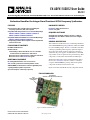
Evaluation Board for the Integer-N and Fractional-N PLL Frequency Synthesizer
PLEASE SEE THE LAST PAGE FOR AN IMPORTANT
WARNING AND LEGAL TERMS AND CONDITIONS.
Rev. A | Page 1 of 28
FEATURES
General-purpose PLL evaluation board, excluding the
frequency synthesizer, VCO, and loop filter
Compatible with integer-N PLLs in a 16-lead TSSOP package
ADF4110, ADF4111, ADF4112, ADF4113, ADF4116,
ADF4117, ADF4118, ADF4106, ADF4107
Compatible with fractional-N PLLs in a 16-lead TSSOP package
ADF4153, ADF4154, ADF4156, ADF4157
Accompanying software allows complete control of synthesizer
functions from a PC
EVALUATION KIT CONTENTS
EV-ADF411XSD1Z board
CD that includes
Self-installing software that allows users to control the
board and exercise all functions of the device
Electronic version of the frequency synthesizer data sheet
Electronic version of the UG-161 user guide
ADDITIONAL EQUIPMENT
PC running Windows XP or more recent version
SDP-S board (system demonstration platform-serial)
ADF41XXBRUZ (see the Features section for applicable parts)
T-package VCO, loop filter components
Spectrum analyzer, oscilloscope (optional)
DOCUMENTS NEEDED
Frequency synthesizer data sheet
UG-161 user guide
REQUIRED SOFTWARE
Analog Devices Int-N PLL software (Version 7 or higher)
Analog Devices Frac-N PLL software (Version 4 or higher)
ADIsimPLL
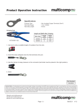
GENERAL DESCRIPTION
This evaluation board allows the user to evaluate the performance
of the ADF41XXBRUZ frequency synthesizers, which are available
in 16-lead TSSOP packages. The
SDP-S controller board allows
software programming of the frequency synthesizer. Figure 1
shows the board, which contains footprints for a frequency
synthesizer, the power supplies, a TCXO reference, and an RF
output. There are also footprints for the passive PLL loop filter
components, a VCO, and an external reference SMA input.
The PLL loop filter values can be generated from the Analog
Devices, Inc.,
ADIsimPLL software tool. Prior to evaluation
setup, the ADF41XXBRUZ, T-package VCO, and loop filter
components should be inserted on the board.
Figure 1 shows the board with all necessary components inserted.
EVALUATION BOARD
Figure 1. EV-ADF411XSD1Z with SDP-S
09146-001
SDP-S
(TO BE PURCHASED
SEPARATELY)
ADF41XXBRUZ
(SAMPLES TO BE PURCHASED SEPARATELY)

UG-161 EV-ADF411XSD1Z User Guide
Rev. A | Page 2 of 28
TABLE OF CONTENTS
Features .............................................................................................. 1
Evaluation Kit Contents ................................................................... 1
Additional Equipment ..................................................................... 1
Documents Needed .......................................................................... 1
Required Software ............................................................................ 1
General Description ......................................................................... 1
Evaluation Board .............................................................................. 1
Revision History ............................................................................... 2
Quick Start Guide ............................................................................. 3
Evaluation Board Hardware ............................................................ 4
Power Supplies .............................................................................. 4
Input Signals .................................................................................. 4
Output Signals............................................................................... 4
Default Operation and Jumper Selection Settings ....................5
System Demonstration Platform (SDP) .....................................5
Evaluation Board Setup Procedure .................................................6
Installing the Int-N PLL Software ...............................................6
Installing the Frac-N PLL Software ......................................... 10
Evaluation Board Software ............................................................ 14
Int-N PLL Software .................................................................... 14
Frac-N PLL Software ................................................................. 16
Evaluation and Test ........................................................................ 18
Evaluation Board Schematics and Artwork ................................ 19
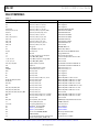
Bill of Materials ............................................................................... 26
Related Links ................................................................................... 27
REVISION HISTORY
6/12—Rev. 0 to Rev. A
Changed EVA L-ADF411XEBZ1 to EV-ADF411XSD1Z .... Universal
Replaced All Sections, Tables, and Figures ..................... Universal
8/11—Revision 0: Initial Version

EV-ADF411XSD1Z User Guide UG-161
Rev. A | Page 3 of 28
QUICK START GUIDE
Follow these steps to evaluate the frequency synthesizer (ADF4110,
ADF4111, ADF4112, ADF4113, ADF4116, ADF4117, ADF4118,
ADF4106, ADF4107, ADF4153, ADF4154, ADF4156, or
ADF4157) after inserting all necessary components on the
board and ensuring that the on-board links are correct with
reference to Table 1:
1. Install the system development platform (SDP) drivers.
2. Install the Int-N or Frac-N PLL software.
3. Connect the SDP-S motherboard to the PC and to the
EV-ADF411XSD1Z.
4. Connect the power supplies to banana connectors (6 V
to 12 V).
5. Run the Int-N or Frac-N PLL software.
6. Select the SDP board and the frequency synthesizer in the
Select Device and Connection tab of the main window.
7. Click the Main Controls tab, and then update all registers.
8. Connect the spectrum analyzer to J2.
9. Measure the results.

UG-161 EV-ADF411XSD1Z User Guide
Rev. A | Page 4 of 28
EVALUATION BOARD HARDWARE
The evaluation board requires the use of an SDP-S motherboard to
program the device. The SDP-S is not included with the evaluation
board. The EV-ADF411XSD1Z schematics are shown in Figure 37,
Figure 38, and Figure 39.
POWER SUPPLIES
The board is powered from external banana connectors. The
voltage can vary between 6 V and 12 V. The power supply circuit
provides 3.0 V to the V
DD
of the frequency synthesizer and allows
the user to choose either 3.0 V or 5 V for the V
P
of the frequency
synthesizer. The default settings for V
DD
and V
P
are 3.0 V and
5 V, respectively. Note that V
DD
should never exceed 3.3 V because
exceeding this voltage level may damage the device.
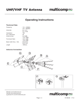
External power supplies can be used to directly drive the
frequency synthesizer. In this case, the user must insert SMA
connectors as shown in Figure 2.
INPUT SIGNALS
A 10 MHz TCXO reference source from Fox Electronics is fitted as
the default option. An external reference generator can also be used
as the reference input. A low noise, high slew rate reference source
is required to achieve the specified performance of the frequency
synthesizer. An SMA connector fitted to J11 can be connected to an
external reference generator and used as the reference source. If
preferable, the edge mount connector, J5, can be inserted and used
instead of J11. To use any external reference option, remove the 0 Ω
R16 and R14 links.
Digital SPI signals are supplied through the SDP connector, J1.
The SDP-S board is recommended. The SDP-Blackfin (SDP-B)
board can also be used, but Resistor R57 must be removed from
the SDP-B board. Some additional spurious low frequencies
may appear if the SDP-B connector is used.
Figure 2. Evaluation Board Silkscreen
OUTPUT SIGNALS
The PLL comprises the frequency synthesizer, a passive loop
filter, and the VCO. The VCO output is available at RFOUT
through a standard SMA connector, J2. The MUXOUT signal
can be monitored at Test Point T8 or at SMA Connector J3.
09146-002

EV-ADF411XSD1Z User Guide UG-161
Rev. A | Page 5 of 28
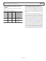
DEFAULT OPERATION AND JUMPER SELECTION
SETTINGS
Link positions and their respective functions are outlined in
Table 1.
Table 1. Link Positions and Functions
Link Position Options Description
LK1 A R1A Not used
B RSET Normal operation
LK2 A GND Hardware power-down
B VDD Normal operation
LK3 (V
DD
) A 5 V Not used
B 3 V Normal operation
LK4 (V
VCO
) A 5 V VCO supply (5 V)
B 3 V VCO supply (3 V)
LK5 (V
P
) A 5 V V
P
supply (5 V)
B 3 V V
P
supply (3 V)
SYSTEM DEMONSTRATION PLATFORM (SDP)
The system demonstration platform (SDP) is a series of controller
boards, interposer boards, and daughter boards that can be used
for easy, low cost evaluation of Analog Devices components and
reference circuits. It is a reusable platform whereby a single con-
troller board can be reused in various daughter board evaluation
systems.
Controller boards connect to the PC via a USB 2.0 high speed
port and provide a range of communication interfaces on a 120-
pin connector. The pinout for this connector is strictly defined.
A receptacle for this 120-pin connector is included on all SDP
daughter boards, component evaluation boards, and Circuits
from the Lab® reference circuit boards. There are two controller
boards in the platform: the SDP-B, which is based on the Blackfin®
ADSP-BF527, and the SDP-S, which is a serial interface only
controller board. The SDP-S has a subset of the SDP-B functionality.
Interposer boards route signals between the SDP 120-pin con-
nector and a second connector. When the second connector is
also a 120-pin connector, the interposer can be used for signal
monitoring of the 120-pin connector signals. Alternatively, the
second connector allows SDP platform elements to be integrated
into a second platform, for example, the BeMicro SDK. More
information on the SDP can be found at www.analog.com/sdp.

UG-161 EV-ADF411XSD1Z User Guide
Rev. A | Page 6 of 28
EVALUATION BOARD SETUP PROCEDURE
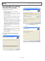
INSTALLING THE INT-N PLL SOFTWARE
Use the following steps to install the SDP drivers and the
Analog Devices Int-N PLL software:
1. Install the Int-N PLL software by double-clicking
ADI_Int-N_Setup.msi.
If you are using Windows XP, follow the instructions in the
Windows XP Int-N PLL Software Installation Guide section
(see Figure 3 to Figure 7).
If you are using Windows Vista or Windows 7, follow the
instructions in the Windows Vista and Windows 7 Int-N
PLL Software Installation Guide section (see Figure 8 to
Figure 12).
Note that the Int-N PLL software requires Microsoft Windows
Installer and Microsoft .NET Framework 3.5 (or higher). The
installer connects to the Internet and downloads Microsoft
.NET Framework automatically. Alternatively, before run
ning ADI_Int-N_Setup.msi, both the installer and .NET
Framework can be installed from the CD provided in the
evaluation board kit.
2. Connect the SDP board (black) to a PC using the supplied
USB cable.
If you are using Windows XP, follow the steps in the Windows
XP SDP-S Board Driver Installation Guide section (see
Figure 13 to Figure 16).
If you are using Windows Vista or Windows 7, the drivers
install automatically.
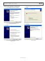
Windows XP Int-N PLL Software Installation Guide
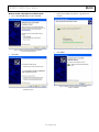
1. Click Next.
Figure 3. Windows XP Int-N PLL Software Installation, Setup Wizard
2. Choose an installation directory, and then click Next.
Figure 4. Windows XP Int-N PLL Software Installation,
Select Installation Folder
3. Click Next.
Figure 5. Windows XP Int-N PLL Software Installation, Confirm Installation
09146-003
09146-004
09146-005

EV-ADF411XSD1Z User Guide UG-161
Rev. A | Page 7 of 28
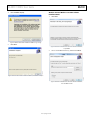
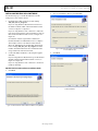
4. Click Continue Anyway.
Figure 6. Windows XP Int-N PLL Software Installation, Logo Testing
5. Click Close.
Figure 7. Windows XP Int-N PLL Software Installation, Installation Complete
Windows Vista and Windows 7 Int-N PLL Software
Installation Guide
1. Click Next.
Figure 8. Windows Vista/Windows 7 Int-N PLL Software Installation,
Setup Wizard
2. Choose an installation directory, and then click Next.
Figure 9. Windows Vista/Windows 7 Int-N PLL Software Installation,
Select Installation Folder
09146-006
09146-007
09146-008
09146-009

UG-161 EV-ADF411XSD1Z User Guide
Rev. A | Page 8 of 28
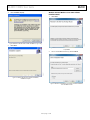
3. Click Next.
Figure 10. Windows Vista/Windows 7 Int-N PLL Software Installation,
Confirm Installation
4. Click Install.
Figure 11. Windows Vista/Windows 7 Int-N PLL Software Installation,
Start Installation
5. Click Close.
Figure 12. Windows Vista/Windows 7 Int-N PLL Software Installation,
Installation Complete
09146-010
09146-011
09146-012

EV-ADF411XSD1Z User Guide UG-161
Rev. A | Page 9 of 28
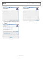
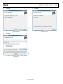
Windows XP SDP-S Board Driver Installation Guide
1. Choose Yes, this time only, and then click Next.
Figure 13. Windows XP SDP-S Board Driver Installation,
Found New Hardware Wizard
2. Click Next.
Figure 14. Windows XP SDP-S Board Driver Installation,
Installation Options
3. Wait for the installation program to copy all the neces
sary files.
Figure 15. Windows XP SDP-S Board Driver Installation, Progress
4. Click Finish.
Figure 16. Windows XP SDP-S Board Driver Installation,
Complete Installation
09146-113
09146-114
09146-115
09146-116

UG-161 EV-ADF411XSD1Z User Guide
Rev. A | Page 10 of 28
INSTALLING THE FRAC-N PLL SOFTWARE
Use the following steps to install the SDP drivers and the
Analog Devices Frac-N PLL software.
1. Install the Frac-N PLL software by double-clicking
ADI_PLL_Frac-N_Setup.msi.
If you are using Windows XP, follow the instructions in
the Windows XP Int-N PLL Software Installation Guide
section (see Figure 17 to Figure 21).
If you are using Windows Vista or Windows 7, follow the
instructions in the Windows Vista and Windows 7 Frac-N
PLL Software Installation Guide section (see Figure 22 to
Figure 26).
Note that the software requires Microsoft Windows
Installer and Microsoft .NET Framework 3.5 (or higher).
The installer connects to the Internet and downloads
Microsoft .NET Framework automatically. Alternatively,
before running ADI_PLL_Frac-N_Setup.msi, both the
installer and .NET Framework can be installed from the
CD provided in the evaluation board kit.
2. Connect the SDP board (black) to a PC using the supplied
USB cable.
If you are using Windows XP, follow the steps in the Windows
XP SDP-S Board Driver Installation Guide section (see
Figure 27 to Figure 30).
If you are using Windows Vista or Windows 7, the drivers
install automatically.
Windows XP Frac-N PLL Software Installation Guide
1. Click Next.
Figure 17. Windows XP Frac-N PLL Software Installation, Setup Wizard
2. Choose an installation directory and click Next.
Figure 18. Windows XP Frac-N PLL Software Installation,
Select Installation Folder
3. Click Next.
Figure 19. Windows XP Frac-N PLL Software Installation,
Confirm Installation
09146-103
09146-104
09146-105

EV-ADF411XSD1Z User Guide UG-161
Rev. A | Page 11 of 28
4. Click Continue Anyway.
Figure 20. Windows XP Frac-N PLL Software Installation, Logo Testing
5. Click Close.
Figure 21. Windows XP Frac-N PLL Software Installation,
Installation Complete
Windows Vista and Windows 7 Frac-N PLL Software
Installation Guide
1. Click Next.
Figure 22. Windows Vista/Windows 7 Frac-N PLL Software Installation,
Setup Wizard
2. Choose an installation directory and click Next.
Figure 23. Windows Vista/Windows 7 Frac-N PLL Software Installation,
Select Installation Folder
09146-106
09146-107
09146-108
09146-109

UG-161 EV-ADF411XSD1Z User Guide
Rev. A | Page 12 of 28
3. Click Next.
Figure 24. Windows Vista/Windows 7 Frac-N PLL Software Installation,
Confirm Installation
4. Click Install.
Figure 25. Windows Vista/Windows 7 Frac-N PLL Software Installation,
Start Installation
5. Click Close.
Figure 26. Windows Vista/Windows 7 Frac-N PLL Software Installation,
Installation Complete
09146-110
09146-111
09146-112

EV-ADF411XSD1Z User Guide UG-161
Rev. A | Page 13 of 28
Windows XP SDP-S Board Driver Installation Guide
1. Choose Yes, this time only, and then click Next.
Figure 27. Windows XP SDP-S Board Driver Installation,
Found New Hardware Wizard
2. Click Next.
Figure 28. Windows XP SDP-S Board Driver Installation,
Installation Options
3. Wait for the installation program to copy all the neces
sary files.
Figure 29. Windows XP SDP-S Board Driver Installation, Progress
4. Click Finish.
Figure 30. Windows XP SDP-S Board Driver Installation,
Complete Installation
09146-127
09146-128
09146-129
09146-130

UG-161 EV-ADF411XSD1Z User Guide
Rev. A | Page 14 of 28
EVALUATION BOARD SOFTWARE
INT-N PLL SOFTWARE
The control software for the EV-ADF411XSD1Z is provided on
the CD included in the evaluation board kit. To install the
software, see the Installing the Int-N PLL Software section.
To run the software, click the ADI PLL Int-N file on the
desktop or in the Start menu.
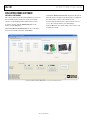
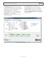
On the Select Device and Connection tab, choose the device
and connection method, and then click Connect.
Confirm that SDP board connected is displayed at the bottom
left of the window (see Figure 31). If this message is not displayed,
the software cannot connect to the evaluation board.
Note that when the SDP board is connected, there is about a
5 sec to 10 sec delay before the status label changes.
From the File menu, the current settings can be saved to and
loaded from a text file.
Figure 31. Int-N PLL Software, Main Window—Select Device and Connection
09146-017

EV-ADF411XSD1Z User Guide UG-161
Rev. A | Page 15 of 28
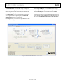
The Main Controls tab controls the PLL settings (see Figure 32).
Use the Reference Frequency text box to set the correct
reference frequency and the reference frequency divider. The
default reference frequency in this box is at 10 MHz.
Use the RF Settings section to control the output frequency.
You can type the desired output frequency in the RF VCO
Output Frequency text box (in megahertz).
In the Registers tab, you can manually input the desired value
to be written to the registers.
In the Sweep and Hop tab, you can make the device sweep a
range of frequencies or hop between two set frequencies.
In the Latches/Registers section at the bottom of the Main
Controls tab of the main window, the values to be written to
each register are displayed. If the background on the text box is
green, the value displayed is different from the value actually on
the device. Click Write R Counter Latch or Write N Counter
Latch to write that value to the device.
Figure 32. Int-N PLL Software Main Window—Main Controls
09146-018

UG-161 EV-ADF411XSD1Z User Guide
Rev. A | Page 16 of 28
FRAC-N PLL SOFTWARE
The control software for the EV-ADF411XSD1Z is provided on
the CD included in the evaluation board kit. To install the
software, see the Installing the Frac-N PLL Software section.
To run the software, click the ADI Frac-N file on the desktop or
in the Start menu.
On the Select Device and Connection tab, choose the device
and connection method, and then click Connect.
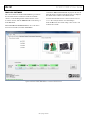
Confirm that SDP board connected is displayed at the bottom
left of the window (see Figure 33). If this message is not displayed,
the software cannot connect to the evaluation board.
Note that when the SDP board is connected, there is about a
5 sec to 10 sec delay before the status label changes.
From the File menu, the current settings can be saved to and
loaded from a text file.
Figure 33. Frac-N PLL Software, Main Window—Select Device and Connection
09146-117

EV-ADF411XSD1Z User Guide UG-161
Rev. A | Page 17 of 28
The Main Controls tab controls the PLL settings (see Figure 34).
Use the Reference Frequency text box to set the correct refer-
ence frequency and the reference frequency divider. The default
reference frequency in this box is 25 MHz (change this value to
10 MHz if using the supplied on-board TCXO).
Use the RF Settings section to control the output frequency.
You can type the desired output frequency in the RF VCO
Output Frequency text box (in megahertz).
In the Registers tab, you can manually input the desired value
to be written to the registers.
In the Sweep and Hop tab, you can make the device sweep a
range of frequencies or hop between two set frequencies.
In the Latches/Registers section at the bottom of the Main
Controls tab of the main window, the values to be written to
each register are displayed. If the background on the text box is
green, the value displayed is different from the value actually on
the device. Click Write Rx (where x = 0 to 3) to write the value
displayed to the device.
Figure 34. Frac-N PLL Software, Main Window—Main Controls
09146-118

UG-161 EV-ADF411XSD1Z User Guide
Rev. A | Page 18 of 28
EVALUATION AND TEST
To evaluate and test the performance of the frequency synthesizer
(ADF4110, ADF4111, ADF4112, ADF4113, ADF4116, ADF4117,
ADF4118, ADF4106, ADF4107, ADF4153, ADF4154, ADF4156,
or ADF4157), use the following procedure:
1. Install the SDP-S software drivers and Int-N or Frac-N PLL
software.
2. Connect the SDP board (black) to a PC using the supplied
USB cable.
3. Connect the SDP-S connector to the EV-ADF411XSD1Z.
4. Connect the power supplies to banana connectors (6 V
to 12 V).
5. Connect a spectrum analyzer to Connector J2.
6. Run the relevant Int-N or Frac-N PLL software.
7. Select the SDP board and the frequency synthesizer in the
Select Device and Connection tab in the main window of
the evaluation board software.
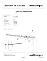
8. In the Main Controls tab in the main window of the evalu-
ation board software, set the VCO center frequency in the RF
VCO Output Frequency text box (Figure 32 uses a 5800 MHz
VCO). Set the required value in the PFD Frequency text box,
and program the Reference Frequency value to equal the
frequency supplied to Connector J11 (or the TCXO). See
Figure 36 for the suggested setup.
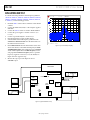
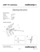
9. Measure the output spectrum. Figure 35 shows a
5800 MHz output.
Figure 35. Spectrum Analyzer Display
Figure 36. Typical Evaluation Setup
09146-019
Ref -8.9 dBm
Att 20 dB
A
Center 5.8 GHz
Span 2 MHz
200 kHz/
3DB
RBW 50 kHz
VBW 200 kHz
SWT 20 ms
-100
-90
-80
-70
-60
-50
-40
-30
-20
-10
low
Date: 29.NOV.2011 18:39:36
SPECTRUM
ANALYZER
PC
EXTERNAL DC
GND
EXTERNAL DC
SUPPLY
TCXO
VCO
LOOP
FILTER
LOCK DETECT LED
PLL
POWER
LED
EXTERNAL
POWER
SWITCH
SDP CONNECTOR
REFERENCE IN/
REFERENCE OUT
PLL
SDP-S BOARD
POWER
SUPPLIES
SIGNAL
GENERATOR
09146-020

EV-ADF411XSD1Z User Guide UG-161
Rev. A | Page 19 of 28
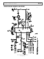
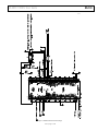
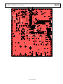
EVALUATION BOARD SCHEMATICS AND ARTWORK
Figure 37. Evaluation Board Schematic (Page 1)
09146-021

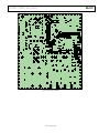
UG-161 EV-ADF411XSD1Z User Guide
Rev. A | Page 20 of 28
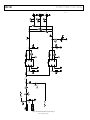
Figure 38. Evaluation Board Schematic (Page 2)
09146-022
Page is loading ...
Page is loading ...
Page is loading ...
Page is loading ...
Page is loading ...
Page is loading ...
Page is loading ...
Page is loading ...
-
 1
1
-
 2
2
-
 3
3
-
 4
4
-
 5
5
-
 6
6
-
 7
7
-
 8
8
-
 9
9
-
 10
10
-
 11
11
-
 12
12
-
 13
13
-
 14
14
-
 15
15
-
 16
16
-
 17
17
-
 18
18
-
 19
19
-
 20
20
-
 21
21
-
 22
22
-
 23
23
-
 24
24
-
 25
25
-
 26
26
-
 27
27
-
 28
28


Analog Devices EV-ADF411XSD1Z User manual
- Type
- User manual
Ask a question and I''ll find the answer in the document
Finding information in a document is now easier with AI
Related papers
-
Analog Devices EV-ADF4002SD1Z User manual
-
-
-
-
-
-
-
-
-
Other documents
-
Samsung SDP-950DXA User guide
-
-
 multicomp pro FLDNYDX5-250 Operating instructions
-
 multicomp pro MP005744 Operating instructions
-
 multicomp pro MC29504 Operating instructions
-
 multicomp pro MP011353 Operating instructions
-
 multicomp pro MP011352 Operating instructions
-
 multicomp pro MP011355 Operating instructions
-
ANALOG DEVICE AD9837 User guide
-
Fujitsu MMBB1155FF77 User manual


