ProSoft Technology PS69-DPS User manual
- Category
- Networking
- Type
- User manual

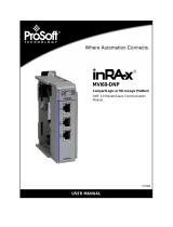
PS69-DPS
CompactLogix or MicroLogix
Platform
Profibus DP Slave Communication
Module
May 9, 2014
USER MANUAL

Your Feedback Please
We always want you to feel that you made the right decision to use our products. If you have suggestions, comments,
compliments or complaints about our products, documentation, or support, please write or call us.
How to Contact Us
ProSoft Technology
5201 Truxtun Ave., 3rd Floor
Bakersfield, CA 93309
+1 (661) 716-5100
+1 (661) 716-5101 (Fax)
www.prosoft-technology.com
Copyright © 2014 ProSoft Technology, Inc., All rights reserved.
PS69-DPS User Manual
May 9, 2014
ProSoft Technology
®
, ProLinx
®
, inRAx
®
, ProTalk
®
, and RadioLinx
®
are Registered Trademarks of ProSoft
Technology, Inc. All other brand or product names are or may be trademarks of, and are used to identify products
and services of, their respective owners.
ProSoft Technology
®
Product Documentation
In an effort to conserve paper, ProSoft Technology no longer includes printed manuals with our product shipments.
User Manuals, Datasheets, Sample Ladder Files, and Configuration Files are provided on the enclosed DVD, and are
available at no charge from our web site: www.prosoft-technology.com
Printed documentation is available for purchase. Contact ProSoft Technology for pricing and availability.
North America: +1.661.716.5100
Asia Pacific: +603.7724.2080
Europe, Middle East, Africa: +33 (0) 5.3436.87.20
Latin America: +1.281.298.9109
Throughout this manual, you will see references to other product names such as:
RIF 1769-DPM
SYCON.net
These product names (RIF 1769, SYCON.net) are legacy versions, and are mentioned for backward compatibility
with existing implementations. These products are now supported and maintained by ProSoft Technology.
The ProSoft and legacy versions of these products may not be interchangeable.

PS69-DPS ♦ CompactLogix or MicroLogix Platform Contents
Profibus DP Slave Communication Module User Manual
ProSoft Technology, Inc. Page 3 of 108
May 9, 2014
Contents
Your Feedback Please ........................................................................................................................ 2
How to Contact Us .............................................................................................................................. 2
ProSoft Technology
®
Product Documentation .................................................................................... 2
Guide to the PS69-DPS User Manual 7
1 Start Here 9
1.1 Software Requirements ........................................................................................... 10
1.2 Hardware Requirements ......................................................................................... 10
1.3 Reference Systems ................................................................................................. 10
1.4 Programmable Controller Functionality ................................................................... 11
1.5 Package Contents ................................................................................................... 12
1.6 Installing the Module in the Rack ............................................................................ 13
1.7 Connecting Your PC to the Processor .................................................................... 16
1.8 PS69-DPS Sample Add-On Instruction Import Procedure ...................................... 17
1.8.1 Create a new RSLogix5000 project ........................................................................ 17
1.8.2 Create the Module ................................................................................................... 18
1.8.3 Import the Ladder Rung .......................................................................................... 20
1.8.4 Adding Multiple Modules (Optional) ........................................................................ 25
1.9 Downloading the Sample Program to the Processor .............................................. 32
1.9.1 Configuring the RSLinx Driver for the PC COM Port .............................................. 33
1.10 Adapter (PROFIBUS-DP-Slave) ............................................................................. 35
2 Configuration and Start-Up 37
2.1 RSLogix 5000 .......................................................................................................... 38
2.1.1 Module Selection ..................................................................................................... 38
2.1.2 Module Properties 1 ................................................................................................ 40
2.1.3 Module Properties 2 ................................................................................................ 41
2.2 RSLogix 500 ............................................................................................................ 42
2.2.1 Module Selection ..................................................................................................... 42
2.2.2 Expansion General Configuration ........................................................................... 43
2.2.3 Generic Extra Data Config ...................................................................................... 44
2.3 Slave Configuration ................................................................................................. 45
2.3.1 General .................................................................................................................... 45
2.3.2 GSD File .................................................................................................................. 45
2.3.3 Configuration by Master .......................................................................................... 45
2.3.4 Configuration by Controller Application ................................................................... 46
2.3.5 Explanation of settable configuration values ........................................................... 47
3 RSLogix Example Program 49
3.1 CompactLogix I/O Example..................................................................................... 50
3.2 CompactLogix Messaging Example ........................................................................ 52

Contents PS69-DPS ♦ CompactLogix or MicroLogix Platform
User Manual Profibus DP Slave Communication Module
Page 4 of 108 ProSoft Technology, Inc.
May 9, 2014
4 Diagnostics and Troubleshooting 55
4.1 Hardware Diagnostics (LED) .................................................................................. 56
4.1.1 CompactLogix ......................................................................................................... 56
4.1.2 MicroLogix 1500...................................................................................................... 56
4.1.3 PS69 LEDs ............................................................................................................. 57
4.2 Troubleshooting ...................................................................................................... 58
4.2.1 CompactLogix I/O LED ........................................................................................... 58
4.2.2 MicroLogix Fault LED ............................................................................................. 58
4.2.3 SYS and COM Status LEDs ................................................................................... 58
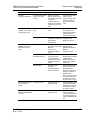
4.2.4 Error Sources and Reasons ................................................................................... 58
4.2.5 Cable ....................................................................................................................... 60
5 Reference 61
5.1 Specifications .......................................................................................................... 62
5.1.1 General Specifications ............................................................................................ 62
5.1.2 Hardware Specifications ......................................................................................... 63
5.1.3 Functional Specifications ........................................................................................ 64
5.1.4 PROFIBUS Interface .............................................................................................. 65
5.2 RSLogix5000 User Defined Data Types ................................................................. 66
5.2.1 Input: DPS_INPUT_ARRAY ................................................................................... 66
5.2.2 Input: DPS_DEV_STATUS_REGISTER ................................................................ 66
5.2.3 Input: DPS_FW_REVISION .................................................................................... 66
5.2.4 Input: DPS_STATUS_FIELD .................................................................................. 67
5.2.5 Output: DPS_OUTPUT_ARRAY ............................................................................ 67
5.2.6 Output: DPS_DEV_COMMAND_REGISTER ......................................................... 67
5.2.7 APP_CONSTANT_PATTERN ................................................................................ 68
5.2.8 APP_DPV1_PROG_CONTROL ............................................................................. 68
5.2.9 APP_DPV1_STAT_COUNTER .............................................................................. 68
5.2.10 DPS_DIAGNOSTIC_CONFIRM ............................................................................. 69
5.2.11 DPS_DIAGNOSTIC_REQUEST ............................................................................. 69
5.2.12 DPS_DPV1C1_ALARM_CONFIRM ....................................................................... 70
5.2.13 DPS_DPV1C1_ALARM_REQUEST ...................................................................... 70
5.2.14 DPS_DPV1C1_RW_INDICATION.......................................................................... 71
5.2.15 DPS_DPV1C1_RW_RESP_CONFIRM .................................................................. 71
5.2.16 DPS_DPV1C1_RW_RESP_REQUEST ................................................................. 72
5.3 PROFIBUS Functionality ........................................................................................ 73
5.3.1 DPV0 Services ........................................................................................................ 73
5.3.2 DPV1 Services ........................................................................................................ 74
5.3.3 Start/Stop Communication ...................................................................................... 74
5.4 Communication ....................................................................................................... 75
5.4.1 IO Communication and IO Memory Map ................................................................ 75
5.4.2 CIP Messaging........................................................................................................ 84
5.5 Constructing a Bus Cable for PROFIBUS DP ........................................................ 99
6 Support, Service & Warranty 103
Contacting Technical Support ........................................................................................................ 103
6.1 Warranty Information ............................................................................................ 105
Index 107

PS69-DPS ♦ CompactLogix or MicroLogix Platform Contents
Profibus DP Slave Communication Module User Manual
ProSoft Technology, Inc. Page 5 of 108
May 9, 2014

Contents PS69-DPS ♦ CompactLogix or MicroLogix Platform
User Manual Profibus DP Slave Communication Module
Page 6 of 108 ProSoft Technology, Inc.
May 9, 2014

PS69-DPS ♦ CompactLogix or MicroLogix Platform Start Here
Profibus DP Slave Communication Module User Manual
ProSoft Technology, Inc. Page 7 of 108
May 9, 2014
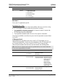
Guide to the PS69-DPS User Manual
Function
Section to Read
Details
Introduction
(Must Do)
Start Here (page 9)
This section introduces the customer to the
module. Included are: package contents,
system requirements, hardware installation, and
basic configuration.
Diagnostic and
Troubleshooting
Diagnostics and
Troubleshooting
(page 55)
This section describes Diagnostic and
Troubleshooting procedures.
Reference
Product Specifications
Functional Overview
Reference (page 61)
Product
Specifications (page
62)
Functional Overview
These sections contain general references
associated with this product, Specifications, and
the Functional Overview.
Support, Service, and
Warranty
Index
Support, Service
and Warranty (page
103)
Index
This section contains Support, Service and
Warranty information.
Index of chapters.

Start Here PS69-DPS ♦ CompactLogix or MicroLogix Platform
User Manual Profibus DP Slave Communication Module
Page 8 of 108 ProSoft Technology, Inc.
May 9, 2014

PS69-DPS ♦ CompactLogix or MicroLogix Platform Start Here
Profibus DP Slave Communication Module User Manual
ProSoft Technology, Inc. Page 9 of 108
May 9, 2014
1 Start Here
In This Chapter
Software Requirements ......................................................................... 10
Hardware Requirements........................................................................ 10
Reference Systems ............................................................................... 10
Programmable Controller Functionality ................................................. 11
Package Contents ................................................................................. 12
Installing the Module in the Rack ........................................................... 13
Connecting Your PC to the Processor ................................................... 16
PS69-DPS Sample Add-On Instruction Import Procedure .................... 17
Downloading the Sample Program to the Processor ............................. 32
Adapter (PROFIBUS-DP-Slave) ............................................................ 35
To get the most benefit from this User Manual, you should have the following
skills:
Rockwell Automation
®
RSLogix™ software: launch the program, configure
ladder logic, and transfer the ladder logic to the processor
Microsoft Windows: install and launch programs, execute menu commands,
navigate dialog boxes, and enter data
Hardware installation and wiring: install the module, and safely connect
PROFIBUS DP and CompactLogix or MicroLogix devices to a power source
and to the PS69-DPS module’s application port(s)
The PS69-DPS module expands the functionality of Rockwell Automation’s
CompactLogix or MicroLogix to include PROFIBUS DP V0/V1. The PS69-DPS is
a more cost-effective option offering more features than the PS69-PDPS, and
supports both I/O control and messaging. Explicit ladder logic CIP message
blocks provide slave status diagnostic data and acyclic messaging.
The PS69-DPS interface appears to the CompactLogix or MicroLogix controller
as a standard I/O module allowing it to be configured via RSLogix5000, or
configuration can be transferred from the Master to the PS69-DPS. For third
party configuration a GSD file is supplied. The slave interface possesses a
diagnostic interface and has rotary switches for setting of the bus address.
Complete program examples for simple and quick start-up are available.
Each module is equipped with LEDs to display communication and device status.

Start Here PS69-DPS ♦ CompactLogix or MicroLogix Platform
User Manual Profibus DP Slave Communication Module
Page 10 of 108 ProSoft Technology, Inc.
May 9, 2014
1.1 Software Requirements
Follows are the software requirements for using the PS69-DPS module within a
CompactLogix system. You must have the following software installed on your
computer unless otherwise noted:
CompactLogix System
RSLogix 5000, V13.00 or higher
MicroLogix 1500 System
RSLogix 500, V6.30 or higher
1.2 Hardware Requirements
The following minimum hardware is required to use the PS69-DPS PROFIBUS
module.
CompactLogix System
Personal Computer
1769: Programmable Controller
1769: Power Supply
1769: Right or Left handed Termination End Cap
Serial Cable for interface to the 1769-Programmable Controller.
MicroLogix 1500 System
Personal Computer
1764: MicroLogix 1500 Programmable Controller
1769: Right handed Termination End Cap
Serial Cable for interface to the 1764-Programmable Controller.
1.3 Reference Systems
The firmware of the communication module PS69-DPS was developed and
tested with following CompactLogix / MicroLogix Controller types and firmware
revisions.
CompactLogix System
PS69-DPS
CompactLogix 1769-L20
CompactLogix 1769-L32E
Firmware V10.2
Firmware V13.18
Firmware V13.28
MicroLogix 1500 System
PS69-DPS
MicroLogix 1500 (Processor 1764-LRP/A Rev2.0)
Firmware V10.2
Firmware: OS 1510; Series C ; Revision 9.0

PS69-DPS ♦ CompactLogix or MicroLogix Platform Start Here
Profibus DP Slave Communication Module User Manual
ProSoft Technology, Inc. Page 11 of 108
May 9, 2014
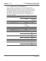
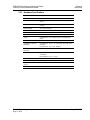
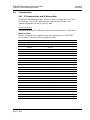
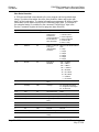
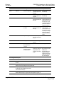
1.4 Programmable Controller Functionality
PROFIBUS-DP supports acyclic services through messages. These PROFIBUS-
DP services are supported by the RSLogix5000 programming tool using CIP
messages. Not all of the 1769 Programmable Controllers support CIP
messaging. If your Controller does not support messaging, these services are not
available.
The basic PROFIBUS-DP acyclic services Global Control or Slave Diag request
are also executable in addition to the CIP method by using the I/O area. Follows
is a matrix of 1769 Programmable Controllers and the functionality that they
support.
CompactLogix System
Processor/ Features
1769-L20
1769 -L30
1769 -L31
1769 -L32E
1769- L35E
I/O
yes
yes
yes
yes
yes
CIP Messaging
no
no
yes
yes
Yes
MicroLogix 1500 System
Processor/ Features
1764 -LRP
1764 -LSP
I/O
yes
yes
CIP Messaging
no
no
yes = functionality supported
no = functionality not supported

Start Here PS69-DPS ♦ CompactLogix or MicroLogix Platform
User Manual Profibus DP Slave Communication Module
Page 12 of 108 ProSoft Technology, Inc.
May 9, 2014
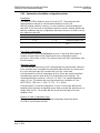
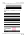
1.5 Package Contents
The following components are included with your PS69-DPS module, and are all
required for installation and configuration.
Important: Before beginning the installation, please verify that all of the following items are
present.
Qty.
Part Name
Part Number
Part Description
1
PS69-DPS Module
PS69-DPS
Profibus DP Slave Communication Module
1
ProSoft Solutions
DVD
DVD-001
Contains sample programs, utilities and
documentation for the PS69-DPS module.
If any of these components are missing, please contact ProSoft Technology
Support for replacement parts.

PS69-DPS ♦ CompactLogix or MicroLogix Platform Start Here
Profibus DP Slave Communication Module User Manual
ProSoft Technology, Inc. Page 13 of 108
May 9, 2014
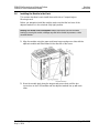
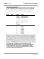
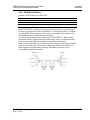
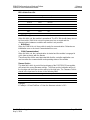
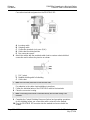
1.6 Installing the Module in the Rack
This section describes how to install the module into a CompactLogix or
MicroLogix rack.
Before you attempt to install the module, make sure that the bus lever of the
adjacent module is in the unlocked (fully right) position.
Warning: This module is not hot-swappable! Always remove power from the rack before
inserting or removing this module, or damage may result to the module, the processor, or other
connected devices.
1 Align the module using the upper and lower tongue-and-groove slots with the
adjacent module and slide forward in the direction of the arrow.
2 Move the module back along the tongue-and-groove slots until the bus
connectors on the PS69 module and the adjacent module line up with each
other.

Start Here PS69-DPS ♦ CompactLogix or MicroLogix Platform
User Manual Profibus DP Slave Communication Module
Page 14 of 108 ProSoft Technology, Inc.
May 9, 2014
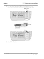
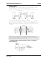
3 Push the module’s bus lever back slightly to clear the positioning tab and
move it firmly to the left until it clicks. Ensure that it is locked firmly in place.
4 Close all DIN-rail latches.

PS69-DPS ♦ CompactLogix or MicroLogix Platform Start Here
Profibus DP Slave Communication Module User Manual
ProSoft Technology, Inc. Page 15 of 108
May 9, 2014
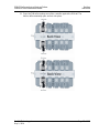
5 Press the DIN-rail mounting area of the controller against the DIN-rail. The
latches will momentarily open and lock into place.

Start Here PS69-DPS ♦ CompactLogix or MicroLogix Platform
User Manual Profibus DP Slave Communication Module
Page 16 of 108 ProSoft Technology, Inc.
May 9, 2014
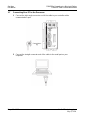
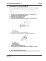
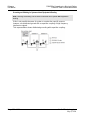
1.7 Connecting Your PC to the Processor
1 Connect the right-angle connector end of the cable to your controller at the
communications port.
2 Connect the straight connector end of the cable to the serial port on your
computer.

PS69-DPS ♦ CompactLogix or MicroLogix Platform Start Here
Profibus DP Slave Communication Module User Manual
ProSoft Technology, Inc. Page 17 of 108
May 9, 2014
1.8 PS69-DPS Sample Add-On Instruction Import Procedure
Note: this section only applies if you are using RSLogix 5000 version 16 or higher.
The following file is required before you start this procedure. Copy the file from
the ProSoft Solutions DVD, or download it from www.prosoft-technology.com.
File Name
Description
AOIPS69DPS_<Version #>.L5X
L5X file contains the Add-On instruction, the user defined data
types, data objects and ladder logic required to set up the
PS69-DPS module
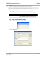
1.8.1 Create a new RSLogix5000 project
1 Open the FILE menu, and then choose NEW…
2 Select REVISION 16

Start Here PS69-DPS ♦ CompactLogix or MicroLogix Platform
User Manual Profibus DP Slave Communication Module
Page 18 of 108 ProSoft Technology, Inc.
May 9, 2014
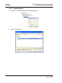
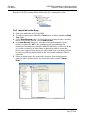
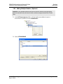
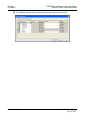
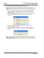
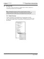
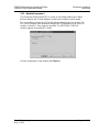
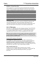
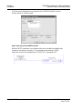
1.8.2 Create the Module
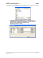
1 Right-click I/O Configuration and choose New Module…
2 Select 1769-MODULE

PS69-DPS ♦ CompactLogix or MicroLogix Platform Start Here
Profibus DP Slave Communication Module User Manual
ProSoft Technology, Inc. Page 19 of 108
May 9, 2014
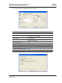
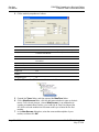
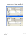
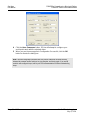
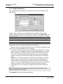
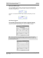
3 Set the Module Properties values as follows:
Parameter
Value
Name
Enter a module identification string. Example: PS69DPS
Description
Enter a description for the module. Example: Profibus DP
Slave Communication Module.
Comm Format
Select Data-INT
Slot
Enter the slot number in the rack where the PS69-DPS
module will be installed.
Input Assembly Instance
101
Input Size
190
Output Assembly Instance
100
Output Size
124
Configuration Assembly Instance
102
Configuration Size
32
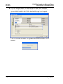
4 On the Connection tab, check or un-check, as desired the Major fault option.

Start Here PS69-DPS ♦ CompactLogix or MicroLogix Platform
User Manual Profibus DP Slave Communication Module
Page 20 of 108 ProSoft Technology, Inc.
May 9, 2014
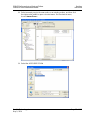
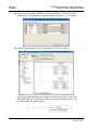
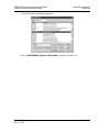
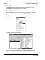
Now the PS69-DPS module will be visible at the I/O Configuration section
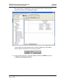
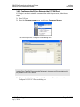
1.8.3 Import the Ladder Rung
1 Open your application in RSLogix 5000.
2 To create a new routine, expand the TASKS folder, and then expand the MAIN
TASK folder.
3 On the MAIN PROGRAM folder, click the right mouse button to open a shortcut
menu. On the shortcut menu, choose NEW ROUTINE.
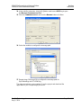
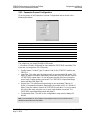
4 In the NEW ROUTINE dialog box, enter the name and description of your
routine, and then click OK. In this example we are demonstrating the
importing of the ladder rung using the default MainRoutine. In the case where
you create a routine by an other name for placing the Add-On instruction,
then in your original routine where your other ladder logic is located you need
to add a rung with a jump instruction to the new routine holding the Add-On
instruction.
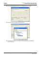
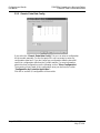
5 Select an empty rung in the new routine, and then click the right mouse
button to open a shortcut menu. On the shortcut menu, choose "IMPORT
RUNG…".
Page is loading ...
Page is loading ...
Page is loading ...
Page is loading ...
Page is loading ...
Page is loading ...
Page is loading ...
Page is loading ...
Page is loading ...
Page is loading ...
Page is loading ...
Page is loading ...
Page is loading ...
Page is loading ...
Page is loading ...
Page is loading ...
Page is loading ...
Page is loading ...
Page is loading ...
Page is loading ...
Page is loading ...
Page is loading ...
Page is loading ...
Page is loading ...
Page is loading ...
Page is loading ...
Page is loading ...
Page is loading ...
Page is loading ...
Page is loading ...
Page is loading ...
Page is loading ...
Page is loading ...
Page is loading ...
Page is loading ...
Page is loading ...
Page is loading ...
Page is loading ...
Page is loading ...
Page is loading ...
Page is loading ...
Page is loading ...
Page is loading ...
Page is loading ...
Page is loading ...
Page is loading ...
Page is loading ...
Page is loading ...
Page is loading ...
Page is loading ...
Page is loading ...
Page is loading ...
Page is loading ...
Page is loading ...
Page is loading ...
Page is loading ...
Page is loading ...
Page is loading ...
Page is loading ...
Page is loading ...
Page is loading ...
Page is loading ...
Page is loading ...
Page is loading ...
Page is loading ...
Page is loading ...
Page is loading ...
Page is loading ...
Page is loading ...
Page is loading ...
Page is loading ...
Page is loading ...
Page is loading ...
Page is loading ...
Page is loading ...
Page is loading ...
Page is loading ...
Page is loading ...
Page is loading ...
Page is loading ...
Page is loading ...
Page is loading ...
Page is loading ...
Page is loading ...
Page is loading ...
Page is loading ...
Page is loading ...
Page is loading ...
-
 1
1
-
 2
2
-
 3
3
-
 4
4
-
 5
5
-
 6
6
-
 7
7
-
 8
8
-
 9
9
-
 10
10
-
 11
11
-
 12
12
-
 13
13
-
 14
14
-
 15
15
-
 16
16
-
 17
17
-
 18
18
-
 19
19
-
 20
20
-
 21
21
-
 22
22
-
 23
23
-
 24
24
-
 25
25
-
 26
26
-
 27
27
-
 28
28
-
 29
29
-
 30
30
-
 31
31
-
 32
32
-
 33
33
-
 34
34
-
 35
35
-
 36
36
-
 37
37
-
 38
38
-
 39
39
-
 40
40
-
 41
41
-
 42
42
-
 43
43
-
 44
44
-
 45
45
-
 46
46
-
 47
47
-
 48
48
-
 49
49
-
 50
50
-
 51
51
-
 52
52
-
 53
53
-
 54
54
-
 55
55
-
 56
56
-
 57
57
-
 58
58
-
 59
59
-
 60
60
-
 61
61
-
 62
62
-
 63
63
-
 64
64
-
 65
65
-
 66
66
-
 67
67
-
 68
68
-
 69
69
-
 70
70
-
 71
71
-
 72
72
-
 73
73
-
 74
74
-
 75
75
-
 76
76
-
 77
77
-
 78
78
-
 79
79
-
 80
80
-
 81
81
-
 82
82
-
 83
83
-
 84
84
-
 85
85
-
 86
86
-
 87
87
-
 88
88
-
 89
89
-
 90
90
-
 91
91
-
 92
92
-
 93
93
-
 94
94
-
 95
95
-
 96
96
-
 97
97
-
 98
98
-
 99
99
-
 100
100
-
 101
101
-
 102
102
-
 103
103
-
 104
104
-
 105
105
-
 106
106
-
 107
107
-
 108
108


ProSoft Technology PS69-DPS User manual
- Category
- Networking
- Type
- User manual
Ask a question and I''ll find the answer in the document
Finding information in a document is now easier with AI
Related papers
-
 ProSoft Technology PS69-DPM User manual
-
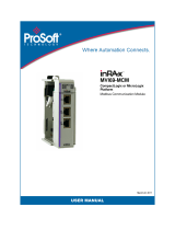 ProSoft Technology MVI69-MCM User manual
-
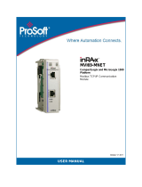 ProSoft Technology MVI69-MNET User manual
-
 ProSoft Technology MVI69-EGD User manual
-
ProSoft Technology 5205-DFNT-PDPS Owner's manual
-
 ProSoft Technology MVI69-DFNT User manual
-
 ProSoft Technology MVI46-PDPS User manual
-
 ProSoft Technology 5204SE-MNET-PDPMV1 Owner's manual
-
ProSoft Technology MVI69-DNPSNET User manual
-
 ProSoft Technology MVI69-DNP User manual


Other documents
-
Eurotherm PC 3000 Owner's manual
-
Allen-Bradley CompactLogix 1769-L20 Installation Instructions Manual
-
schmersal SD-I-U Series Operating instructions
-
Niles DPS-1 Owner's manual
-
Toshiba PA912 User manual
-
INVT EC-TX803 PROFIBUS-DP Communication Expansion Modules User manual
-
 Rockwell Automation 1769-L31 Installation Instructions Manual
-
ESD CAN-DP PROFIBUS-DP/CAN Gateway Owner's manual
-
Kollmorgen AKT-PRB-000-000 Installation guide
-
ICP DAS USA I-7550 User manual
