Page is loading ...

INSTRUCTION MANUAL
MODEL 9110AH
NITROGEN OXIDES ANALYZER
SERIAL NO. _______________
TELEDYNE ANALYTICAL INSTRUMENTS
16830 CHESTNUT STREET
CITY OF INDUSTRY, CA 91749-1020
TOLL-FREE: 888-789-8168
FAX: 626-961-2538
TEL: 626-934-1500
WEB SITE: www.teledyne-ai.com
01620
REV. F
Copyright 1999 TELEDYNE Inc. 07/06/99


TELEDYNE Model 9110AH NO
X
Analyzer Operator Manual, 01620, Rev. F
ii
SAFETY MESSAGES
Your safety and the safety of others is very important. We have provided many important safety messages in
this manual. Please read these messages carefully.
A safety message alerts you to potential hazards that could hurt you or others. Each safety message is
associated with a safety alert symbol. These symbols are found in the manual and inside the instrument. The
definition of these symbols is described below:
GENERAL WARNING/CAUTION: Refer to the instructions for details on the
specific danger.
CAUTION: Hot Surface Warning
CAUTION: Electrical Shock Hazard
Technician Symbol: All operations marked with this symbol are to be performed
by qualified maintenance personnel only.
Electrical Ground: This symbol inside the instrument marks the central safety
grounding point for the instrument.
CAUTION
The analyzer should only be used for the purpose
and in the manner described in this manual.
If you use the analyzer in a manner other than that for which
it was intended, unpredictable behavior could ensue with
possible hazardous consequences.

TELEDYNE Model 9110AH NO
X
Analyzer Operator Manual, 01620, Rev. F
iii
TABLE OF CONTENTS
SAFETY MESSAGES..................................................................................II
TABLE OF CONTENTS.............................................................................III
LIST OF FIGURES................................................................................... VII
LIST OF TABLES ................................................................................... VIII
1 HOW TO USE THIS MANUAL...............................................................1-1
2 GETTING STARTED.............................................................................2-1
2.1 UNPACKING ...........................................................................................................................2-1
2.2 ELECTRICAL AND PNEUMATIC CONNECTIONS .........................................................................2-1
2.3 INITIAL OPERATION.................................................................................................................2-6
3 SPECIFICATIONS, WARRANTY...........................................................3-1
3.1 SPECIFICATIONS.....................................................................................................................3-1
3.2 WARRANTY............................................................................................................................3-2
4 THE M9110AH NO
X
ANALYZER ...........................................................4-1
4.1 PRINCIPLE OF OPERATION......................................................................................................4-1
4.2 OPERATION SUMMARY...........................................................................................................4-4
4.2.1 Sensor Module, Reaction Cell, Detector....................................................................4-4
4.2.2 Pneumatic Sensor Board.............................................................................................4-4
4.2.3 Computer Hardware and Software .............................................................................4-5
4.2.4 V/F Board......................................................................................................................4-5
4.2.5 Front Panel...................................................................................................................4-5
4.2.6 Power Supply Module...................................................................................................4-7
4.2.7 Pump, Valves, Pneumatic System...............................................................................4-7
4.2.8 Ozone Generator...................................................................................................... 4-10
4.2.9 NO
2
- NO Converter ................................................................................................. 4-10
5 SOFTWARE FEATURES.......................................................................5-1
5.1 INDEX TO FRONT PANEL MENUS............................................................................................5-1
5.1.1 Sample Menu................................................................................................................5-4
5.1.2 Set-Up Menu ................................................................................................................5-5
5.2 SAMPLE MODE.......................................................................................................................5-9
5.2.1 Test Functions..............................................................................................................5-9
5.2.2 CAL, CALS, CALZ, Calibration Functions............................................................... 5-13

TELEDYNE Model 9110AH NO
X
Analyzer Operator Manual, 01620, Rev. F
iv
5.3 SET-UP MODE ................................................................................................................... 5-15
5.3.1 Configuration Information (CFG) ............................................................................. 5-15
5.3.2 Automatic Calibration (AutoCal)............................................................................... 5-15
5.3.3 Data Acquisition System (DAS) ............................................................................... 5-16
5.3.4 Range Menu.............................................................................................................. 5-18
5.3.5 Password Enable ...................................................................................................... 5-21
5.3.6 Time of Day Clock..................................................................................................... 5-21
5.3.7 Diagnostic Mode ....................................................................................................... 5-21
5.3.8 Communications Menu............................................................................................. 5-21
5.3.9 Variables Menu (VARS) ........................................................................................... 5-22
5.4 M9110AH OPERATING MODES.......................................................................................... 5-22
5.4.1 NO/NO
x
/NO
2
Switching Mode .................................................................................. 5-23
5.4.2 NO
x
Only Mode.......................................................................................................... 5-24
5.4.3 NO Only Mode........................................................................................................... 5-24
5.5 4-20 MA CURRENT LOOP................................................................................................... 5-24
5.6 STATUS OUTPUT................................................................................................................ 5-25
5.7 RS-232 INTERFACE ........................................................................................................... 5-25
5.7.1 Setting up the RS-232 Interface............................................................................... 5-26
5.7.2 Command Summary.................................................................................................. 5-29
5.7.3 TEST Commands and Messages............................................................................ 5-33
5.7.4 WARNING Commands and Messages................................................................... 5-34
5.7.5 CALIBRATION Commands and Messages............................................................ 5-35
5.7.6 DIAGNOSTIC Commands and Messages.............................................................. 5-36
5.7.7 DAS Commands and Messages.............................................................................. 5-37
5.7.8 VARIABLES Commands and Messages................................................................. 5-39
6 OPTIONAL HARDWARE AND SOFTWARE..........................................6-1
6.1 RACK MOUNT OPTIONS.........................................................................................................6-1
6.2 ZERO/SPAN VALVES OPTION..................................................................................................6-2
6.2.1 Autocal - Setup Zero/Span Valves..............................................................................6-2
6.3 ISOLATED 4-20 MA CURRENT LOOP OPTION.........................................................................6-4
6.4 MOLYBDENUM CONVERTER OPTION......................................................................................6-5
6.5 EXTERNAL DESICCANT CANISTER OPTION .............................................................................6-5
6.6 ALTERNATE BYPASS FLOW ORIFICE OPTION..........................................................................6-5
6.7 EXTERNAL CONVERTER OPTION............................................................................................6-5
7 CALIBRATION AND ZERO/SPAN CHECKS.........................................7-1
7.1 MANUAL ZERO/SPAN CHECK OR CAL WITH ZERO/SPAN GAS IN THE SAMPLE PORT...............7-3
7.2 MANUAL ZERO/SPAN CHECK WITH ZERO/SPAN VALVES OPTION ............................................7-6
7.3 DYNAMIC ZERO/SPAN CALIBRATION USING AUTOCAL ............................................................7-7
7.4 USE OF ZERO/SPAN VALVES WITH REMOTE CONTACT CLOSURE...........................................7-8
7.5 NO ONLY MODE CALIBRATION ..............................................................................................7-9
7.6 NO
X
ONLY MODE CALIBRATION .............................................................................................7-9

TELEDYNE Model 9110AH NO
X
Analyzer Operator Manual, 01620, Rev. F
v
7.7 CALIBRATION REQUIREMENTS FOR AUTORANGE OR REMOTE RANGE....................................7-9
7.8 CALIBRATION REQUIREMENTS FOR INDEPENDENT RANGE................................................... 7-10
7.9 CALIBRATION QUALITY........................................................................................................ 7-10
7.10 CONVERTER EFFICIENCY COMPENSATION ........................................................................ 7-11
7.11 RECOMMENDATIONS FOR CEM APPLICATIONS ................................................................. 7-12
7.11.1 Calibration Gasses................................................................................................. 7-12
7.11.2 Calibration Frequency............................................................................................. 7-13
7.11.3 Converter Efficiency............................................................................................... 7-13
8 MAINTENANCE ....................................................................................8-1
8.1 MAINTENANCE SCHEDULE......................................................................................................8-1
8.2 REPLACING THE SAMPLE PARTICULATE FILTER......................................................................8-2
8.3 REPLACING THE CONVERTER.................................................................................................8-4
8.4 CLEANING THE REACTION CELL.............................................................................................8-6
8.5 PNEUMATIC LINE INSPECTION ............................................................................................. 8-10
8.6 LEAK CHECK PROCEDURE.................................................................................................. 8-13
8.7 LIGHT LEAK CHECK PROCEDURE........................................................................................ 8-13
8.8 PROM REPLACEMENT PROCEDURE..................................................................................... 8-14
9 TROUBLESHOOTING AND ADJUSTMENTS.......................................9-1
9.1 OPERATION VERIFICATION - DIAGNOSTIC TECHNIQUES...........................................................9-3
9.1.1 Fault Diagnosis with TEST Variables..........................................................................9-3
9.1.2 Fault Diagnosis with WARNING Messages...............................................................9-8
9.1.3 Fault Diagnosis using DIAGNOSTIC Mode ............................................................ 9-10
9.1.4 M9110AH Internal Variables.................................................................................... 9-17
9.1.5 Test Channel Analog Output..................................................................................... 9-19
9.1.6 Factory Calibration Procedure................................................................................. 9-20
9.2 PERFORMANCE PROBLEMS................................................................................................. 9-24
9.2.1 AC Power Check....................................................................................................... 9-24
9.2.2 Flow Check................................................................................................................ 9-25
9.2.3 No Response to Sample Gas .................................................................................. 9-25
9.2.4 Negative Output......................................................................................................... 9-26
9.2.5 Excessive Noise....................................................................................................... 9-26
9.2.6 Unstable Span........................................................................................................... 9-27
9.2.7 Unstable Zero............................................................................................................ 9-28
9.2.8 Inability to Span......................................................................................................... 9-28
9.2.9 Inability to Zero.......................................................................................................... 9-28
9.2.10 Non-Linear Response............................................................................................ 9-29
9.2.11 Slow Response....................................................................................................... 9-30
9.2.12 Analog Output Doesn't Agree With Display Concentration.................................. 9-30
9.3 SUBSYSTEM TROUBLESHOOTING AND ADJUSTMENTS......................................................... 9-31
9.3.1 Computer, Display, Keyboard................................................................................... 9-31
9.3.2 RS-232 Communications ......................................................................................... 9-34

TELEDYNE Model 9110AH NO
X
Analyzer Operator Manual, 01620, Rev. F
vi
9.3.3 Voltage/Frequency (V/F) Board............................................................................... 9-37
9.3.4 Status/Temp Board................................................................................................... 9-43
9.3.5 Power Supply Module................................................................................................ 9-45
9.3.6 Ozone Generator...................................................................................................... 9-49
9.3.7 Flow/Pressure Sensor.............................................................................................. 9-53
9.3.8 NO
x
Sensor Module .................................................................................................. 9-58
9.3.9 Z/S Valves ................................................................................................................. 9-63
9.3.10 Pneumatic System.................................................................................................. 9-64
10 M9110AH SPARE PARTS LIST.........................................................10-1
APPENDIX A ELECTRICAL SCHEMATICS............................................ A-1

TELEDYNE Model 9110AH NO
X
Analyzer Operator Manual, 01620, Rev. F
vii
LIST OF FIGURES
FIGURE 2-1: REMOVAL OF SHIPPING SCREWS & CHECK FOR CORRECT POWER.............................2-3
FIGURE 2-2: REAR PANEL...............................................................................................................2-4
FIGURE 2-3: INLET AND EXHAUST VENTING RECOMMENDATIONS ....................................................2-5
FIGURE 2-4: FRONT PANEL.......................................................................................................... 2-10
FIGURE 2-5: ASSEMBLY LAYOUT.................................................................................................. 2-12
FIGURE 4-1: BLOCK DIAGRAM.........................................................................................................4-3
FIGURE 4-2: EXTERNAL PUMP PACK...............................................................................................4-9
FIGURE 5-1: SAMPLE MENU TREE ..................................................................................................5-2
FIGURE 5-2: SETUP MENU TREE ....................................................................................................5-3
FIGURE 8-1: REPLACING THE PARTICULATE FILTER ........................................................................8-3
FIGURE 8-2: CONVERTER ASSEMBLY..............................................................................................8-5
FIGURE 8-3: REACTION CELL ASSEMBLY........................................................................................8-8
FIGURE 8-4: SAMPLE/BYPASS FLOW CONTROL ASSEMBLY.............................................................8-9
FIGURE 8-5: PNEUMATIC DIAGRAM............................................................................................... 8-11
FIGURE 8-6: PNEUMATIC DIAGRAM WITH ZERO/SPAN VALVES ...................................................... 8-12
FIGURE 9-1: SPAN CALIBRATION VOLTAGE................................................................................... 9-23
FIGURE 9-2: CPU BOARD JUMPER SETTINGS ............................................................................. 9-33
FIGURE 9-3: RS-232 PIN ASSIGNMENTS..................................................................................... 9-35
FIGURE 9-4: V/F BOARD JUMPER SETTINGS................................................................................ 9-42
FIGURE 9-5: POWER SUPPLY MODULE LAYOUT........................................................................... 9-47
FIGURE 9-6: ELECTRICAL BLOCK DIAGRAM .................................................................................. 9-48
FIGURE 9-7: OZONE GENERATOR SUBSYSTEM............................................................................ 9-52
FIGURE 9-8: FLOW/PRESSURE SENSOR ...................................................................................... 9-55
FIGURE 9-9: NO
X
SENSOR MODULE ............................................................................................ 9-56
FIGURE 9-10: NO
X
SENSOR MODULE.......................................................................................... 9-57
FIGURE 9-11: PMT COOLER SUBSYSTEM................................................................................... 9-60
FIGURE 9-12: HIGH VOLTAGE POWER SUPPLY............................................................................ 9-62

TELEDYNE Model 9110AH NO
X
Analyzer Operator Manual, 01620, Rev. F
viii
LIST OF TABLES
TABLE 2-1: FINAL TEST AND CALIBRATION VALUES....................................................................... 2-13
TABLE 2-1: FINAL TEST AND CALIBRATION VALUES (CONTINUED)................................................. 2-14
TABLE 4-1: SAMPLING MODES OF THE M9110AH ..........................................................................4-1
TABLE 4-2: FRONT PANEL STATUS LED'S......................................................................................4-6
TABLE 4-3: OZONE GENERATOR START-UP TIMING ..................................................................... 4-10
TABLE 5-1: M9110AH SAMPLE MENU STRUCTURE .......................................................................5-4
TABLE 5-2: M9110AH SETUP MENU .............................................................................................5-5
TABLE 5-2: M9110AH SETUP MENU (CONTINUED).......................................................................5-6
TABLE 5-3: M9110AH SETUP MENU .............................................................................................5-7
TABLE 5-4: M9110AH SETUP MENU .............................................................................................5-8
TABLE 5-5: DAS DATA CHANNEL EDITING................................................................................... 5-17
TABLE 5-6: CALIBRATE, SETUP PASSWORDS............................................................................... 5-21
TABLE 5-7: M9110AH OPERATING MODES................................................................................. 5-23
TABLE 5-8: STATUS OUTPUT PIN ASSIGNMENTS ......................................................................... 5-25
TABLE 5-9: RS-232 PORT SETUP - FRONT PANEL...................................................................... 5-26
TABLE 5-10: RS-232 SWITCHING FROM TERMINAL MODE TO COMPUTER MODE ........................ 5-28
TABLE 5-11: RS-232 TERMINAL MODE EDITING KEYS................................................................. 5-28
TABLE 5-12: RS-232 COMMAND SUMMARY ................................................................................ 5-30
TABLE 5-13: RS-232 COMMAND SUMMARY ................................................................................ 5-31
TABLE 5-14: RS-232 INTERFACE COMMAND TYPES.................................................................... 5-32
TABLE 5-15: RS-232 TEST MESSAGES....................................................................................... 5-33
TABLE 5-16: RS-232 WARNING MESSAGES................................................................................ 5-34
TABLE 5-17: RS-232 CALIBRATION MESSAGES........................................................................... 5-35
TABLE 5-18: RS-232 CALIBRATION COMMANDS.......................................................................... 5-36
TABLE 5-19: RS-232 DIAGNOSTIC COMMAND SUMMARY ............................................................ 5-37
TABLE 6-1: ZERO/SPAN VALVE OPERATION ....................................................................................6-2
TABLE 6-2: SETUP AUTOMATIC ZERO/SPAN CHECKING OR CALIBRATION........................................6-3
TABLE 6-3: ACTION OF MODE FIELD IN AUTOCAL..........................................................................6-4
TABLE 7-1: TYPES OF ZERO/SPAN CHECK AND CALIBRATION..........................................................7-2
TABLE 7-2: MANUAL ZERO CALIBRATION PROCEDURE - ZERO GAS THRU SAMPLE PORT................7-3
TABLE 7-3: ENTER EXPECTED SPAN GAS CONCENTRATIONS PROCEDURE.....................................7-4
TABLE 7-4: MANUAL SPAN CALIBRATION PROCEDURE - SPAN GAS THRU SAMPLE PORT.................7-5
TABLE 7-5: MANUAL ZERO CHECK PROCEDURE - Z/S VALVES........................................................7-6
TABLE 7-6: MANUAL SPAN CHECK PROCEDURE - Z/S VALVES........................................................7-7
TABLE 7-7: Z/S VALVE MODES WITH REMOTE CONTACT CLOSURE................................................7-8
TABLE 7-8: CALIBRATION REQUIREMENTS FOR AUTORANGE OR REMOTE RANGE........................ 7-10
TABLE 7-9: CALIBRATION QUALITY CHECK................................................................................... 7-11
TABLE 7-10: CONVERTER EFFICIENCY - AUTOMATIC CALCULATION ............................................. 7-12
TABLE 8-1: PREVENTATIVE MAINTENANCE SCHEDULE.....................................................................8-1

TELEDYNE Model 9110AH NO
X
Analyzer Operator Manual, 01620, Rev. F
ix
TABLE 9-1: TEST FUNCTIONS .........................................................................................................9-4
TABLE 9-1: TEST FUNCTIONS (CONTINUED)...................................................................................9-5
TABLE 9-1: TEST FUNCTIONS (CONTINUED)...................................................................................9-6
TABLE 9-1: TEST FUNCTIONS (CONTINUED)...................................................................................9-7
TABLE 9-2: FRONT PANEL WARNING MESSAGES ............................................................................9-9
TABLE 9-2: FRONT PANEL WARNING MESSAGES (CONTINUED)................................................... 9-10
TABLE 9-3: SUMMARY OF DIAGNOSTIC MODES ............................................................................ 9-11
TABLE 9-4: DIAGNOSTIC MODE - SIGNAL I/O................................................................................ 9-12
TABLE 9-4: DIAGNOSTIC MODE - SIGNAL I/O (CONTINUED).......................................................... 9-13
TABLE 9-4: DIAGNOSTIC MODE - SIGNAL I/O (CONTINUED).......................................................... 9-14
TABLE 9-4: DIAGNOSTIC MODE - SIGNAL I/O (CONTINUED).......................................................... 9-15
TABLE 9-5: MODEL 9110AH VARIABLES...................................................................................... 9-18
TABLE 9-6: TEST CHANNEL READINGS......................................................................................... 9-19
TABLE 9-6: TEST CHANNEL READINGS (CONTINUED)................................................................... 9-20
TABLE 9-7: MOTHERBOARD JUMPER SETTINGS........................................................................... 9-39
TABLE 9-1: V/F BOARD SWITCH SETTINGS.................................................................................. 9-39
TABLE 9-8: POWER SUPPLY MODULE SUBASSEMBLIES................................................................ 9-46
TABLE 9-9: POWER SUPPLY MODULE LED OPERATION............................................................... 9-49
TABLE 9-10: OZONE GENERATOR CONTROL CONDITIONS........................................................... 9-50
TABLE 10-1: TELEDYNE M9110AH SPARE PARTS LIST........................................................... 10-1
TABLE 10-1: TELEDYNE M9110AH SPARE PARTS LIST (CONTINUED)..................................... 10-2
TABLE 10-1: TELEDYNE M9110AH SPARE PARTS LIST (CONTINUED)..................................... 10-3
TABLE 10-2: TELEDYNE MODEL 9110AH EXPENDABLES KIT ................................................ 10-4
TABLE 10-3: TELEDYNE MODEL 9110AH LEVEL 1 SPARES KIT WITH MINI-HICON CONVERTER
............................................................................................................................................. 10-5
TABLE 10-4: TELEDYNE MODEL 9110AH LEVEL 1 SPARES KIT WITH MOLYBDENUM
CONVERTER.......................................................................................................................... 10-6
TABLE A-1: ELECTRICAL SCHEMATICS ...........................................................................................A-1

TELEDYNE Model 9110AH NO
X
Analyzer Operator Manual, 01620, Rev. F
x
INTENTIONALLY BLANK

TELEDYNE Model 9110AH NO
X
Analyzer Operator Manual, 01620, Rev. F
1-1
1 HOW TO USE THIS MANUAL
The Model 9110AH has been designed to produce accurate data, be serviceable, reliable and
easy to use. The M9110AH's microprocessor continually checks operating parameters such as
temperature, flow, and critical voltages. The instruments design uses top mounted, modular
components with captive screws to facilitate repair and ease of access. If you encounter any
difficulty refer to the Troubleshooting Section 9 - General Hints.
We recognize that the need for information from this manual changes as time passes. When the
instrument first arrives, it is necessary to get it up and running quickly and verify its correct
operation. As time passes, more detailed information is often required on special
configurations, calibration alternatives and other operational details. Finally there is the need
for periodic maintenance and to quickly troubleshoot problems to assure maximum reliability
and data integrity.
To address these needs, we have created three indexes to the information inside. They are:
Table of Contents:
Outlines the contents of the manual in the order the information is presented. This is a good
overview of the topics covered in the manual. There is also a list of Tables and a list of Figures.
Index to M9110AH Front Panel Menus:
The Menu Index briefly describes the front panel menus and refers you to other sections of the
manual that have a detailed explanation of each menu selection.
Troubleshooting Section 9:
The Troubleshooting Section allows you to diagnose and repair the instrument based on
variables in the TEST menu, the results of DIAGNOSTIC tests, and performance faults such as
excessive noise or drift. The troubleshooting section also explains the operation, adjustment,
diagnosis and testing of each instrument subsystem.
If you are unpacking the instrument for the first time, please refer to Getting Started in
Section 2.

TELEDYNE Model 9110AH NO
X
Analyzer Operator Manual, 01620, Rev. F
1-2
INTENTIONALLY BLANK

TELEDYNE Model 9110AH NO
X
Analyzer Operator Manual, 01620, Rev. F
2-1
2 GETTING STARTED
2.1 Unpacking
CAUTION
Your safety and the safety of others is very important. We
have provided many important safety messages in this manual.
Please read these messages carefully.
To avoid personal injury, always use two persons to
lift and carry the Model 9110AH.
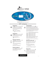
1. Before operation it is necessary to remove the shipping hold-down screws. Remove the
instrument cover, then remove 2 screws as shown in Figure 2-1.
2. Also check for internal shipping damage, and generally inspect the interior of the instrument
to make sure all circuit boards and other components are in good shape.
3. Please check the voltage and frequency label on the serial number tag on the rear panel.
Compare that to your local power before plugging in the Instrument.
2.2 Electrical and Pneumatic Connections
1. Refer to Figure 2-2 to locate the rear panel electrical and pneumatic connections.
2. Attach the pump to the “Exhaust Out” port on the instrument rear panel. The exhaust from
the pump should also be vented to atmospheric pressure.
3. Attach the sample inlet line to the sample inlet port. For initial testing, sample gas can be
calibration gas or stack gas. The pressure of the sample gas at the inlet port should be at
ambient pressure and constant. See Figure 2-3.
4. If desired, attach the analog output connections to a strip chart recorder and/or datalogger.
Refer to Figure 9-4 - Analog Output Voltage Ranges - for switch settings. Factory default
setting is 0-5 VDC.
5. Connect the power cord to the correct voltage line, then turn to Section 2.3 Initial
Operation.

TELEDYNE Model 9110AH NO
X
Analyzer Operator Manual, 01620, Rev. F
2-2
WARNING
Analyzer Exhaust – O
3
Scrubber – Pump Pack
Danger – Analyzer exhaust contains ozone.
Ozone scrubber must always be present between
analyzer exhaust and pump.
Vent pump exhaust to well ventilated area at atmosphere
pressure FIRE or EXPLOSION HAZARD.
WARNING
Lethal voltages present inside case.
Do not operate with cover off during normal operation.
Before operation check for correct
input voltage and frequency.
Do not operate without proper chassis grounding.
Do not defeat the ground wire on power plug.
Turn off analyzer power before disconnecting
electrical subassemblies.

TELEDYNE Model 9110AH NO
X
Analyzer Operator Manual, 01620, Rev. F
2-3
Figure 2-1: Removal of Shipping Screws & Check for Correct Power

TELEDYNE Model 9110AH NO
X
Analyzer Operator Manual, 01620, Rev. F
2-4
Figure 2-2: Rear Panel

TELEDYNE Model 9110AH NO
X
Analyzer Operator Manual, 01620, Rev. F
2-5
Figure 2-3: Inlet and Exhaust Venting Recommendations

TELEDYNE Model 9110AH NO
X
Analyzer Operator Manual, 01620, Rev. F
2-6
2.3 Initial Operation
1. Turn on the instrument power.
2. The display should immediately light, showing the computer’s memory configuration, then
the instrument type - M9110AH. If you are unfamiliar with the M9110AH, we recommend
that you read the overview Section 4 before proceeding. A diagram of the software menu
trees is in Figure 5-1 and Figure 5-2.
3. The M9110AH requires about 30 minutes for all internal components to come to
temperature. During this time the ozone generator power is OFF until the membrane dryer
has time to purge itself, therefore there will be no response from the instrument, even if
span gas is coming in the sample port. Many warning conditions are not displayed during
this time, even though temperatures and other conditions are out of specification. All
warning messages are enabled after 30 minutes of operation.
4. While waiting for instrument temperatures to stabilize, you can check for correct operation
by using some of the M9110AH's diagnostic and test features.
5. Examine the TEST functions by comparing the values listed in Table 2-1 to those in the
display. Remember that as the instrument warms up the values may not have reached their
final values yet. If you would like to know more about the meaning and utility of each
TEST function refer to Table 9-1. Also, now is a good time to verify that the instrument was
shipped with the options you ordered. Table 2-1 also contains the list of options. Section 6
covers setting up the options.
6. Electric Test and Optic Test both generate simulated signals in the M9110AH.
A. Electric Test checks the electronics of the PMT signal path. To operate Electric Test from
the front panel:
1) Scroll the TEST function to PMT.
2) Press SETUP-MORE-DIAG, then press ENTR to accept the default password. Scroll
to Electric Test and press ENTR to turn it on. Instrument responses should come to
the values indicated in Table 2-1. To turn off this test press EXIT. For more
information on the circuitry being tested refer to the Troubleshooting Section 9.1.3.2.
B. Optic Test is an "end to end" test of the analyzer HVPS-PMT-detector-electronics-
computer. It simulates a signal by turning on a LED in the Sensor Module. To operate
Optic Test from the front panel:
1) Scroll the TEST function to PMT.
2) Press SETUP-MORE-DIAG, then press ENTR to accept the default password. Scroll
to Optic Test and press ENTR to turn on optic test. Instrument response should come
up to the values indicated in Table 2-1. To turn off this test press EXIT. To return to
the SAMPLE mode press EXIT until SAMPLE is displayed in the upper left display.
For more information about OT operation see Section 9.1.3.3.

TELEDYNE Model 9110AH NO
X
Analyzer Operator Manual, 01620, Rev. F
2-7
7. When the instrument is warmed up, re-check the TEST functions against Table 2-1. All of
the readings should compare closely with those in the table. If they do not see Section 9.1.1.
The next task is to calibrate the analyzer. There are several ways to do a calibration, they are
summarized in Table 7-1. For a preliminary checkout we recommend calibration with span
gas coming in through the sample port. The procedure is:
Step 1 - Set the range, then enter the expected NO
x
and NO span gas concentrations:
Step Number Action Comment
1. Press
CAL-CONC-NOX
This key sequence causes the M9110AH to prompt for the
expected span concentration. Enter the span value by pressing
the key under each digit until the expected value is set.
2. Press ENTR ENTR stores the expected NO
x
span value. The internal
formulas are adjusted to compute this number when span gas
concentration is input into the instrument.
3. Press
CAL-CONC-NO
In the same CAL-CONC sub menu press the NO button and
enter the expected NO span value. As before this value will be
used in the internal formulas to compute the NO concentration
value.
4. Press ENTR ENTR stores the expected NO span value. The internal
formulas are adjusted to compute this number when span gas
concentration is input into the instrument.
5. Press EXIT Returns instrument to SAMPLE mode.
6. Press
SETUP-RNGE-
MODE-SNGL
If necessary, you may want to change ranges. Normally the
instrument is shipped in single range mode set at 100 ppm. We
recommend doing the initial checkout on the 100 ppm range.
7. Press
SETUP-RNGE-
SET
After SETUP-RNGE-SET, enter 100 and press ENTR. The
instrument will now be in the 100 ppm range.
/