Page is loading ...

WE3107 v.110413
SAVE THIS MANUAL
You will need this manual for safety instructions, operating procedures, and warranty.
Put it and the original sales invoice in a safe, dry place for future reference.
CONSERVEZ CE GUIDE
Vous aurez besoin de ce guide pour les instructions de sécurité, les procédures d’utilisation et la garantie.
Conservez-le dans un endroit sûr et sec pour référence future.
QUESTIONS? 1-800-567-8979
Model
:
Our Customer Service staff are ready to provide assistance.
If a part is damaged or missing, replacement parts can be
shipped from our facility.
For help with assembly, or for additional product
information, call our North American toll-free number:
1-800-567-8979
Notre personnel de service à la clientèle sera prêt à
fournir assistance. Si une pièce est endommagée ou
manquante, des remplacements seront expédiés de notre
usine.
Pour de l’aide avec l’assemblage, ou pour des
informations additionnelles sur le produit, appeller notre
numéro sans frais nord-américain : 1-800-567-8979
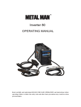
WAVE 200KD
AC/DC Pulse TIG/ARC Welder

2
CATALOGUE
GENERAL SAFETY RULES
TECHNICAL SPECIFICATION
KNOW YOUR WELDER
INSTALLAT
ION
OPERATION
TROUB
LESHOOTING
DIAGRAM & PARTS LIST
WARRANTY

3
GENERAL SAFETY RULES
WARNING: Read and understand all instructions. Failure to follow all instructions listed below
may result in serious injury.
CAUTION: Do not allow persons to operate or assemble this WAVE 200KD until they have
read this manual and have developed a thorough understanding of how the WAVE 200KD works.
WARNING: The warnings, cautions, and instructions discussed in this instruction manual
cannot cover all possible conditions or situations that could occur. It must be understood by the
operator that common sense and caution are factors which cannot be built into this product, but must
be supplied by the operator.
1.1 Your Welding Environment
-Keep the environment you will be welding in free from flammable materials.
-Always keep a fire extinguisher accessible to your welding environment.
-Always have a qualified person install and operate this equipment.
-Make sure the area is clean, dry and ventilated. Do not operate the welder in humid, wet or poorly
ventilated areas.
-Always have your welder maintained by a qualified technician in accordance with local, state and
national codes.
-Always be aware of your work environment. Be sure to keep other people, especially children, away
from you while welding.
-Keep harmful arc rays shielded from the view of others.
-Mount the welder on a secure bench
or cart that will keep the welder secure and prevent it from tipping over or falling.
1.2 Your Welder’s Condition
-Check ground cable, power cord and welding cable to be sure the insulation is not damaged. Always
replace or repair damaged components before using the welder.
-Check all components to ensure they are clean and in good operating condition before use.
1.3 Use of Your Welder
Do not operate the welder if the output cable, electrode, torch, wire or wire feed system is wet. Do not
immerse them in water. These components and the welder must be completely dry before attempting to
use them.
-Follow the instructions in this manual.
-Keep welder in the off position when not in use.
-Connect ground lead as close to the area being welded as possible to ensure a good ground.
-Do not allow any body part to come in contact with the welding wire if you are in contact with the
material being welded, ground or electrode from another welder.
-Do not weld if you are in an awkward position. Always have a secure stance while welding to prevent
accidents. Wear a safety harness if working above ground.

4
-Do not drape cables over or around your body.
-Wear a full coverage helmet with appropriate shade (see ANSI Z87.1 safety standard) and safety
glasses while welding.
-Wear proper gloves and protective clothing to prevent your skin from being exposed to hot metals, UV
and IR rays.
-Do not overuse or overheat your welder. Allow proper cooling time between duty cycles.
-Keep hands and fingers away from moving parts and stay away from the drive rolls.
-Do not point torch at any body part of yourself or anyone else.
-Always use this welder in the rated duty cycle to prevent excessive heat and failure.
1.4 Specific Areas of Danger, Caution or Warning
Electrical Shock
Electric arc welders can produce a shock that can cause injury or death. Touching
electrically live parts can cause fatal shocks and severe burns. While welding, all metal
components connected to the wire are electrically hot. Poor ground connections are a hazard, so
secure the ground lead before welding.
-Wear dry protective apparel: coat, shirt, gloves and insulated footwear.
-Insulate yourself from the work piece. Avoid contacting the work piece or ground.
- Do not attempt to repair or maintain the welder while the power is on.
-Inspect all cables and cords for any exposed wire and replace immediately if found.
-Use only recommended replacement cables and cords.
-Always attach ground clamp to the work piece or work table as close to the weld area as possible.
-Do not touch the welding wire and the ground or grounded work piece at the same time.
-Do not use a welder to thaw frozen pipes.
Fumes and Gases
-Fumes emitted from the welding process displace clean air and can result in injury or death.
-Do not breathe in fumes emitted by the welding process. Make sure your breathing air is clean and
safe.
-Work only in a well-ventilated area or use a ventilation device to remove welding fumes from the
environment where you will be working.
-Do not weld on coated materials (galvanized, cadmium plated or containing zinc, mercury or barium).
They will emit harmful fumes that are dangerous to breathe. If necessary use a ventilator, respirator
with air supply or remove the coating from the material in the weld area.
-The fumes emitted from some metals when heated are extremely toxic. Refer to the material safety
data sheet for the manufacturer’s instructions.
-Do not weld near materials that will emit toxic fumes when heated. Vapors from cleaners, sprays and
degreasers can be highly toxic when heated.
UV and IR Arc Rays
The welding arc produces ultraviolet (UV) and infrared (IR) rays that can cause injury to
your eyes and skin. Do not look at the welding arc without proper eye protection.
-Always use a helmet that covers your full face from the neck to top of head and to the back of each
ear.
-Use a lens that meets ANSI standards and safety glasses. For welders under 160 Amps output, use a

5
shade 10 lens; for above 160 Amps, use a shade 12. Refer to the ANSI standard Z87.1 for more
information.
-Cover all bare skin areas exposed to the arc with protective clothing and shoes. Flame-retardant cloth
or leather shirts, coats, pants or coveralls are available for protection.
-Use screens or other barriers to protect other people from the arc rays emitted from your welding.
-Warn people in your welding area when you are going to strike an arc so they can protect themselves.
Fire Hazards
Do not weld on containers or pipes that contain or have had flammable, gaseous or liquid
combustibles in them. Welding creates sparks and heat that can ignite flammable and
explosive materials.
-Do not operate any electric arc welder in areas where flammable or explosive materials are present.
-Remove all flammable materials within 35 feet of the welding arc. If removal is not possible, tightly
cover them with fireproof covers.
-Take precautions to ensure that flying sparks do not cause fires or explosions in hidden areas, cracks
or areas you cannot see.
-Keep a fire extinguisher close in the case of fire.
-Wear garments that are oil-free with no pockets or cuffs that will collect sparks.
-Do not have on your person any items that are combustible, such as lighters or matches.
-Keep work lead connected as close to the weld area as possible to prevent any unknown, unintended
paths of electrical current from causing electrical shock and fire hazards.
-To prevent any unintended arcs, cut wire back to ¼" stick out after welding.
Hot Materials
Welded materials are hot and can cause severe burns if handled improperly.
-Do not touch welded materials with bare hands.
-Do not touch MIG gun nozzle after welding until it has had time to cool down.
Sparks/Flying Debris
Welding creates hot sparks that can cause injury. Chipping slag off welds creates flying
debris.
-Wear protective apparel at all times: ANSI-approved safety glasses or shield, welder’s hat and ear
plugs to keep sparks out of ears and hair.
Electromagnetic Field
-Electromagnetic fields can interfere with various electrical and electronic devices such as
pacemakers.
-Consult your doctor before using any electric arc welder or cutting device
-Keep people with pacemakers away from your welding area when welding.
-Do not wrap cable around your body while welding.
-Wrap MIG gun and ground cable together whenever possible.
-Keep MIG gun and ground cables on the same side of your body.

6
Shielding Gas Cylinders Can Explode
High pressure cylinders can explode if damaged, so treat them carefully.
-Never expose cylinders to high heat, sparks, open flames, mechanical shocks or arcs.
-Do not touch cylinder with MIG gun.
-Do not weld on the cylinder
-Always secure cylinder upright to a cart or stationary object.
-Keep cylinders away from welding or electrical circuits.
-Use the proper regulators, gas hose and fittings for the specific application.
-Do not look into the valve when opening it.
-Use protective cylinder cap whenever possible
1.5 Proper Care, Maintenance and Repair
-Always have power disconnected when working on internal components.
- Do not touch or handle PC board without being properly grounded with a wrist strap. Put PC board in
static proof bag to move or ship.
-Do not put hands or fingers near moving parts such as drive rolls of fan
WAVE 200KD USE AND CARE
• Do not modify the WAVE 200KD in any way. Unauthorized modification may impair the function
and/or safety and could affect the life of the equipment. There are specific applications for which the
WAVE 200KD was designed.
• Always check of damaged or worn out parts before using the WAVE 200KD. Broken parts will
affect the WAVE 200KD operation. Replace or repair damaged or worn parts immediately.
• Store idle WAVE 200KD. When WAVE 200KD is not in use, store it in a secure place out of the
reach of children. Inspect it for good working condition prior to storage and before re-use.
Notice: * If the welder continues to work too long time, the 【Protection Indicator】on the panel
would be on, indicating that the inner temperature rise inside the welder had exceed the
designed permitted temperature. At this time, stop the welding work, wait until the welder cooled inside
and the 【Protection Indicator】 turned off, then continue to work again;
* Cut off the power switch and Argon valve, before leaving the welding place temporarily or after the
welding worked finished;
* Welders should wear canvas work clothes and welding face shield to prevent arc light and heat
radiation;
* Put light-proof screen around the work area to prevent others influenced by the arc lights.
* Flammable, explosive items could not be put near the welding area;
* Every outlet of the welder should be connected and earthed correctly.
Notice: The cover protection degree of the WAVE series Square Wave AC/DC pulsed inverter
TIG welder is IP21S.When the welder is operated, do not insert finger or round stick diameter less than
12.5mm (especially metal stick) into the welder; Do not allow to press heavily onto the welder.

7
TECHNICAL SPECIFICATION
TERM UNIT WAVE 200KD
Rated Input Voltage V 220
Power Frequency Hz 50/60
Rated Input Capacity KVA 7.9
Rated Input Current A 36
Output No Load Voltage V 65
Rated Working Voltage V 18
DC Argon Welding Current A 5~ 200
AC Argon Welding Current A 10~ 200
Stick Welding Current A 5~ 170
Current Up Time S 0~ 15
Current Drop Time S 0~ 25
Pulse Frequency Hz 0.5~ 250
Pulse Width Adjustment
(DC)
%
15~ 85
Clear Area Control( AC) % 15~ 65
Gas Stop Delay Time S 0~ 30
Rated Duty Cycle % 35
Cooling Type Air cooling
Effiency η ≥ 85%
Power Factor Cosφ 0.92
Insulation Degree H
Cover Protection Degree IP IP21S
Weight kg 19.5
Dimension L×W×H mm 500*240*410
No special advice on above parameter. The nameplate parameter on the welder is prior.

8
Welding regulations parameter table (only for reference)
Mode
Material
Type
Designe
d Joint
WORK
Thicknes
s
(mm)
Wire
Dia
Φ
(mm)
Welding
Current
(A)
Polarity
Argon
Flow
(dm
3
/mi
n)
Tungste
n Stick
Dia Φ
(mm)
Angle
Top Dia
Φ
(mm)
Vertical
Joint
1.6~3.0 50~90 1.0 12~20° 0.12~0.25
V groove
>3.0~6.0
1.6~2.5
70~120
8~12
1.6 25~30° 0.50~0.75
DC
Stainless
Steel
X groove
>6.0~12
2.5~3.2 100~150
DC
Positive
10~14 2.4 35~45° 0.75~1.10
Vertical
Joint
1~2.5 1.6~2.5 45~90 2~6 2~3
V groove 3~6 2~4 90~180 10~12 3~4
AC
Pure
Aluminium,
Alu-Mag
Alloy
X groove 8~12 4~5 150~220
Positive
12~16 4~5
90° 1.50
KNOW YOUR WELDER
Description
WAVE200KD is a digitization model can be used for MMA、ACTIG 、DCTIG and PULSE TIG, the
parameters can be preset and showed, welding current and voltage can real-time display, this is very
easy operation.
1. Front panel
1. 1. Know the Front panel
1.2. Current display
To show the preset current when setting and the welding current when working.
Voltage disply
Status indicator
Procedure parameter
2T/4T switch
Gas check knob
Parameter positive
knob
AC/DC transfer knob
Pulse switch
Current display
Parameter knob
Adjustment knob
Welding mode knob

9
1.3. AC/DC transfer knob
Use this knob to choose the AC or DC, when AC indicator light, means the machine is under AC
mode. When DC indicator light, means the machine is under DC mode.
1.4. Pulse switch
Use this knob to choose whether you need the pulse, when the indicator light, means it is under
pulse mode.
1.5. Welding mode knob
Use this knob to choose the welding mode, can be used MMA、HF TIG and contact-type TIG.
1.6. Parameter knob and positive knob
Use this knob to choose the different procedure. When selected a procedure, the corresponding
indicator light, then use adjustment knob to adjust the parameter.
1.7. Adjustment knob
Use this knob to adjust the parameter, and the parameter can be showed on the display.
1.8. Gas check knob
This machine has the gas check function, use knob to check the gas. Press this knob, the gas
check indicator light, air valve works, that means the gas circuit is well working. Press this knob again,
the indicator extinguish, gas check function does not work.
1.9. Voltage display
To show the preset current when setting and the welding current when working.
1.10. Procedure parameter display
This part is to show the procedure, when the indicator lights, the corresponding parameter can be
adjusted with the adjustment knob. See following details:
1 Pre-flow Time indicator light 8
Pulse frequency indicator light(PULSE)
2
Hot start current indicator light(MMA)
9
Background current indicator light(PULSE)
3
Arc starting current indicator light(4T)
10
Minus grade time indicator light (4T)
4
Uphill time indicator light(4T)
11
Arc stopping current indicator light(4T)
5
Welding current indicator light(CC)
12 Gas delay time indicator light
6
Peak current indicator light(PULSE)
13
Clear area width(ACTIG)/ arc force(MMA)
7
Pulse width indicator light(PULSE)
14
AC frequency(ACTIG)
1.11.1. Thermal protection:
This machine use NTC for temperature sensing element to real time monitoring the temperature
of the critical component to protect it.
1.11.2. Overvoltage protection:
1
2
3
4
5 6
7
8
9 10
11
12
14 13

10
When the input voltage is below or over the specified voltage, the machine will cut off the power
to protect itself until the input voltage is available.
INSTALLATION
1. POWER REQUIREMENT - AC single phase 220V, 60 HZ with a 50 amp circuit breaker is required.
DO NOT OPERATE THIS UNIT if the ACTUAL power source voltage is less than 220 volts AC or
greater than 240 volts AC.
• High voltage danger from power source! Consult a qualified electrician for proper
installation of receptacle. This welder must be grounded while in use to protect the operator
from electrical shock.
• Do not remove grounding prong or alter the plug in any way. Do not use any adapters
between the welder's power cord and the power source receptacle. Make sure the POWER
switch is OFF when connecting your welder's power cord to a properly grounded 220 VAC,
60 HZ, Single Phase, 50 Amp input power supply.
2. EXTENSION CORD - We do not recommend an extension cord because of the voltage drop they
produce. This drop in voltage can affect the performance of the welder. If you need to use an extension
cord, we recommend you check with a qualified electrician and your local electrical codes for your
specific area. Do not use an extension cord over 25 ft. in length.
3. MMA mode connection method
4. TIG mode connection method
Earth clamp
Electrode holder
Earth clamp
TIG torch

11
5. Input connection method
EXPOSURE TO A WELDING ARC IS EXTREMELY HARMFUL TO THE EYES AND SKIN!
Prolonged exposure to the welding arc can cause blindness and burns. Never strike an arc or
begin welding until you are adequately protected. Wear flame-proof welding gloves, a heavy
long sleeved shirt, trousers without cuffs, high topped shoes, and an ANSI approved welding
helmet.
OPERATION
High voltage danger from power source! Consult a qualified electrician for proper
installation of receptacle at the power source. This welder must be grounded while in use to
protect the operator from electrical shock. If you are not sure if your outlet is properly grounded,
have it checked by a qualified electrician. Do not cut off the grounding prong or alter the plug in
any way and do not use any adapter between the welder's power cord and the power source
receptacle. Make sure the POWER switch is OFF then connect your welder's power cord to a
properly grounded 220 VAC, 60 HZ, single phase, 50 amp power source.
1. MMA: DC Stick arc welding
Set the【Welding mode knob】to “ ”,adjust the【Adjustment knob】to change the welding current.
The hot start current “ ”and arc force current “
”can be adjusted at this mode according to the
welding materials.
NOTICE:If set【Welding mode knob】to “ ”,just the hot start current “ ”and arc force current
“ ”can be adjusted.
Remote
control box
Input power
Gas cylinder

12
2. TIG:
2.1 DC TIG welding
Set the【Welding mode knob】to “ ”,and【AC/DC transfer knob】to DC“ ”,would enter
into DC TIG welding mode. In this mode to adjust by “Parameter knob” ”Parameter positive knob”:
【 】to adjust the Pre-flow time
【 Ic 】to adjust the welding current;
【 】to adjust the stopping gas delay time;
Choose【2step,4step switch】set on different gears to choose the welding method “2 step ”、“four
step ” (See the details introduction is “Technical Instruction”)
Step1:
Press this knob, choose MMA, the
current display shows the pre-set
current,voltage display shows the
open circuit voltage.
Step2:
Press this knob to choose the
parameter
Step3:
Use this adjustment to adjust the
parameter selected on Step2
Step3:
Use this adjustment to adjust
the parameter selected on Step2
Step2:
Press this knob to choose the
parameter
Step1:
Press this knob, choose TIG

13
2.2 DC pulse TIG welding
Set 【Welding mode knob】to “TIG ”,【AC/DC transfer knob】to “DC ” , 【Pulse switch】
set on “Pulse” would enter into the by “Parameter knob””Parameter positive knob”:
【 】 to adjust the Pre-flow time;
【 】 to adjust the pulse peak current;
【 】 to adjust the Pulse width;
【 】 to adjust the Pulse frequency;
【 】 to adjust the Pulse Background current;
【 】 to adjust the stopping gas delay time;
2.3 Trigger Mode Control Button (HF TIG and LIFT TIG Mode only)
The trigger mode control is used to switch the functionality of the torch trigger between 2T (normal),
and 4T (latch mode).
2.3.1 2T Normal Mode
In this mode, the torch trigger must remain depressed for the welding output to be active. Press and
hold the torch trigger to activate the power source (weld). Release the torch trigger switch to cease
welding.
NOTE
in this operation mode,the function of UP SLOPE and DOWN SLOPE is not used!

14
2.3.2 4T Latch Mode
This
mode of welding is mainly used for long welding runs to reduce operator fatigue. In this mode the
operator
can press and release the torch trigger and the output will remain active. To deactivate the
power
source, the trigger switch must again be depressed and realized, thus eliminating the need for
the
operator to hold the torch trigger.
Note
that when operating in GTAW (HF and LIFT TIG modes), the power source will remain activated
until
the selected down slope time has elapsed
NOTE
This
Up Slope operates in (4T) TIG modes only and is used to set the time for the
wel
d current to ramp up, after the torch trigger switch has been pressed then released,
from Initial Current to High or BASE current.
2.4 AC TIG welding
Se
t 【Welding mode knob】to “TIG
” and 【AC/DC transfer knob】to “AC ” would enter
into
AC TIG welding mode. Then to choose by “Parameter knob””Parameter positive knob”:
【 】 to adjust the Pre-flow time;
【
IIc 】 to adjust the welding current;
【 】 to adjust the stopping gas delay time;
【 】 to adjust the clear area width;
【 】 to adjust the AC square wave frequency;
Choose
【2step,4step switch】set on different gears to choose the welding method “2 step ”、“four
ste
p ” (See the details introduction is “Technical Instruction”)

15
2.5 AC pulse TIG welding
Set 【Welding mode knob】to “TIG ” and 【AC/DC transfer knob】to “AC ”, 【Pulse
switch】set on “Pulse” would enter into AC pulse TIG welding mode. Then to choose by “Parameter
knob””Parameter positive knob”:
【 】 to adjust the Pre-flow time;
【 】 to adjust the pulse peak current;
【 】 to adjust the Pulse width;
【 】 to adjust the Pulse frequency;
【 】 to adjust the Pulse Background current;
【 】 to adjust the stopping gas delay time;
【 】 to adjust the clear area width;
【 】 to adjust the AC square wave frequency;
Choose【2step,4step switch】set on different gears to choose the welding method “2 step ”、“four
step ” (See the details introduction is “Technical Instruction”)
2.6 LIFT TIG welding
Set 【Welding mode knob】to “TIG
”, let the TIG torch contact the workpiece, press the switch,
at this time there will be a 50A arc starting current, press the switch more than 0.5s(Pre-flow time not
included), then lift the torch, make the distance between the torch and workpiece is 2~4mm, then start
the welding.
3. Stick welding skill
3.1 Welding positions
There are two basic positions, for welding: Flat and Horizontal. Flat welding is generally easier, faster,
and allows for better penetration. If possible, the work piece should be positioned so that the bead will
run on a flat surface.
3.2 Preparing the Joint
Before welding, the surface of work piece needs to be free of dirt, rust, scale, oil or paint or it will create
brittle and porous welds. If the base metal pieces to be joined are thick or heavy, it may be necessary to
bevel the edges with a metal grinder, the correct bevel should be around 60 degree. See following
picture:

16
Based on different welding position, there are different welding joint, see following images for more
information.
3.3 GROUND CLAMP CONNECTION
Clear any dirt, rust, scale, oil or paint on the ground clamp. Make certain you have a good solid ground
connection. A poor connection at the ground clamp will waste power and heat. Make sure the ground
clamp touches the metal.
3.4 ELECTRODE
The welding electrode is a rod coated with a layer of flux. When welding, electrical current flows
between the electrode (rod) and the grounded metal work piece. The intense heat of the arc between
the rod and the grounded metal melts the electrode and the flux. For best performance on this unit, we
suggest the use of 6013 electrodes.

17
3.5 SELECTING THE PROPER ELECTRODE
There is no golden rule that determine the exact rod or heat setting required for every situation. The
type and thickness of metal and the position of the work piece determine the electrode type and the
amount of heat needed in the welding process. Heavier and thicker metals required more amperage. It
is best to practice your welds on scrap metal which matches the metal you intend to work with to
determine correct heat setting and electrode choice. See the following helpful trouble shooting tips to
determine if you are using a correct electrode.
3.5.1. When proper rod is used:
3.5.1.a. The bead will lay smoothly over the work without ragged edges
3.5.1.b. The base metal puddle will be as deep as the bead that rises above it
3.5.1.c. The welding operation will make a crackling sound similar to the sound of eggs frying
3.5.2. When a rod too small is used;
3.5.2. a. The bead will be high and irregular
3.5.2. b. The arc will be difficult to maintain
3.5.3. When the rod is too large
3.5.3. a. The arc will burn through light metals
3.5.3. b. The bead will undercut the work
3.5.3. c. The bead will be flat and porous
3.5.3. d. Rod may be freeze or stick to work piece
Note: Rate of travel over the work also affects the weld. To ensure proper penetration and enough
deposit of rod, the arc must be moved slowly and evenly along the weld seam.
3.6 SETTING THE AMPERAGE CONTROL
The welder has an infinite current control. It is capable of welding with electrodes up to 3/32” diameter.
There is no golden rule that determines the exact amperage required for every situation. It is best to
practice your welds on scrap metal which matches the metals you intend to work with to determine
correct setting for your job. The electrode type and the thickness of the work piece metal determine the
amount of heat needed in the welding process. Heavier and thicker metals require
more voltage (amperage), whereas lighter and thinner metals require less voltage (amperage). Consult
the welding electrode packaging for recommended welding amperage range.
3.7 WELDING TECHNIQUES
The best way to teach yourself how to weld is with short periods of practice at regular intervals. All
practice welds should be done on scrap metal that can be discarded. Do not attempt to make any
repairs on valuable equipment until you have satisfied yourself that your practice welds are of good
appearance and free of slag or gas inclusions.

18
3.7.1 Holding the electrode
The best way to grip the electrode holder is the way that feels most comfortable to you. Position the
Electrode to the work piece when striking the initial arc it may be necessary to hold the electrode
perpendicular to the work piece. Once the arc is started the angle of the electrode in relation to the work
piece should be between 10 and 30 degrees. This will allow for good penetration, with minimal spatter.
3.7.2 Striking the arc
EXPOSURE TO A WELDING ARC IS EXTREMELY HARMFUL TO THE EYES AND SKIN!
Prolonged exposure to the welding arc can cause blindness and burns. Never strike an arc or
begin welding until you are adequately protected. Wear flame-proof welding gloves, a heavy
long sleeved shirt, trousers without cuffs, high topped shoes, and an ANSI approved welding
helmet.
Scratch the work piece with the end of electrode to start arc and then raise it quickly about 1/8 inch gap
between the rod and the work piece, see following picture
It is important that the gap be maintained during the welding process and it should be neither too wide
or too narrow. If too narrow, the rod will stick to the work piece. If too wide, the arc will be extinguished.
It needs much practice to maintain the gap. The beginners may usually get sticker or arc extinguishing.
When the rod is stuck to the work piece, gently rock it back and forth to make them separate. If not, a
short circuit will occur and it will break the welder. A good arc is accompanied by a crisp, cracking
sound. The sound is similar to that made by eggs frying. To lay a weld bead, only 2 movements are
required; downward (as the electrode is consumed) and in the direction the weld is to be laid, as in
following figure:
3.7.3 Types of weld bead
The following paragraphs discuss the most commonly used arc welding beads.
The stringer bead
Formed by traveling with the electrode in a straight line while keeping the electrode
centered over the weld joint.

19
The weave bead
Used when you want to deposit metal over a wider space than would be possible with
a stringer bead. It is made by weaving from side to side while moving with the electrode. It is best to
hesitate momentarily at each side before weaving back the other way.
3.7.4 Welding position
Flat position
It is easiest of the welding positions and is most commonly used. It is best if you can weld
in the flat position if at all possible as good results are easier to achieve.
The horizontal position
it is performed very much the same as the flat weld except that the angle is
different such that the electrode, and therefore the arc force, is directed more toward the metal above
the weld joint. This more direct angle helps prevent the weld puddle from running downward while still
allowing slow enough travel speed to achieve good penetration. A good starting point for your electrode
angle is about 30 degrees DOWN from being perpendicular to the work piece.
3.7.5 Judge the good weld bead
When the trick of establishing and holding an arc has been learned, the next step is learning how to run
a good bead. The first attempts in practice will probably fall short of acceptable weld beads. Too long of
an arc will be held or the travel speed will vary from slow to fast (see following)
A. Weld speed is too fast.
B. Weld speed is too slow.
C. Arc is too long.
D. Ideal weld.
A solid weld bead requires that the electrode be moved slowly and steadily along the weld seam.
Moving the electrode rapidly or erratically will prevent proper fusion or create a lumpy, uneven bead.
ELECTRIC SHOCK CAN KILL! To prevent ELECTRIC SHOCK, do not perform any welding while
standing, kneeling, or lying directly on the grounded workpiece.
Stringer Bead Weave Bead
Flat Position
Horizontal Position

20
3.7.6 Finish the bead
As the coating on the outside of the electrode burns off, it forms an envelope of protective gases around
the weld. This prevents air from reaching the molten metal and creating an undesirable chemical
reaction. The burning coating, however, forms slag. The slag formation appears as an accumulation of
dirty metal scale on the finished weld. Slag should be removed by using a chipping hammer.
PEENING THE SLAG FROM A WELD JOINT CUASES SMALL CHIPS OF METAL TO FLY
THROUGH THE AIR! Metallic chips flying through the air can cause eye injury or injury to other
parts of the head, hands or exposed portions of the body. Wear goggles or safety glasses with
side shields and protect the hands and other exposed parts of the body with protective
garments, or if possible, work with a shield between the body and the work piece.
The intense heat produced at the arc sets up strains in the metal joined by welding. Peening the weld
not only removes the scale left behind in the welding but relieves the internal strains developed by the
heating and cooling process.
4. TIG welding skill
Gas Tungsten Arc Welding (GTAW) or TIG (Tungsten Inert Gas) as it is commonly
referred to, is a welding process in which fusion is produced by an electric arc that is
established between a single tungsten (non-consumable) electrode and the work piece.
Shielding is obtained from a welding grade shielding gas or welding grade shielding gas
mixture which is generally Argon based. A filler metal may also be added manually in
some circumstances depending on the welding application.
/