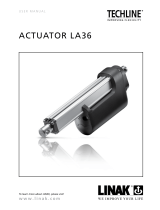
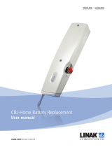
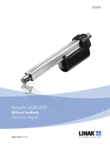
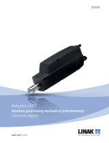
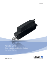
Linak BusLink LA25 User manual

Type
User manual

This manual is also suitable for

Linak BusLink LA25 is an advanced actuator configurator that offers comprehensive control over IC actuators. With its user-friendly interface, you can easily calibrate, configure, and monitor your actuator's performance. Connect your actuator to a PC via USB and unlock a range of features, including virtual limit setting, current limit adjustment, and speed control. Additionally, you can choose from various feedback types, including PWM, single hall, current feedback, and voltage feedback.

Linak BusLink LA25 is an advanced actuator configurator that offers comprehensive control over IC actuators. With its user-friendly interface, you can easily calibrate, configure, and monitor your actuator's performance. Connect your actuator to a PC via USB and unlock a range of features, including virtual limit setting, current limit adjustment, and speed control. Additionally, you can choose from various feedback types, including PWM, single hall, current feedback, and voltage feedback.

LINAK.COM/TECHLINE
BusLink
User Guide
2
Guide to connecting the actuator to BusLink .......................................................... 3-4
Configure the IC actuator with BusLink 2 software ............................................... 5-11
Controls ............................................................................................................................ 5-7
Configure .................................................................................................................. 5
Calibration ................................................................................................................. 6
Virtual- and Current Limit ........................................................................................... 7
Speed ........................................................................................................................ 8
Soft Stop/Soft Sart...................................................................................................... 8
Feedback Types ............................................................................................................... 9-11
PWM ......................................................................................................................... 9
Single Hall ................................................................................................................. 9
Current Feedback ..................................................................................................... 10
Voltage Feedback ..................................................................................................... 10
Monitoring .............................................................................................................. 11
Service ..................................................................................................................... 11
IC Parallel........................................................................................................................ 12
IC Parallel Configuration .......................................................................................... 12
Critical and Non-critical ............................................................................................ 12
Contents
3
Contents
Guide to connect the actuator to BusLink
Actuators with IC - Integrated Controllers from LINAK
®
can be configured via the BusLink Configuration Software.
Please follow the three steps to connect your actuator to BusLink.
1
Start by downloading the free BusLink software here:
WWW.LINAK.COM/SEGMENTS/TECHLINE/TECH-
TRENDS/IC-AND-BUS-ACTUATORS/
LA14/LA25 IC (blue interface): 0147999
LA33/LA36/LA37 IC (blue interface): 0367999
LA36/LA37 Modbus (yellow interface): 0367998
LA36 CAN bus (green interface): 0367997
LA14/LA25 CAN bus (green interface): 0147997
BusLink cable ordering numbers - include 1 USB2LIN cable and 1 Interface cable:
LA14
LA25 LA36LA33 LA37
4
2
LA33/LA36/LA37
3
12V or 24V
In order to connect your actuator
to the PC tool you will need two
separate cables:
1 USB2LIN cable.
1 interface cable.
Start by connecting the two cables.
Please note that the cables must
be purchased separately from the
actuator.
Before connecting the power
supply:
Connect the interface cable to the
actuator...
When changing the actuator’s signal cable with the BusLink cable, it is important that this is done carefully in order to protect
the plugs and pins. Please make sure that the plug is in the right place and fully pressed in before mounting the cable lid.
Cable connection
... and plug in the USB2LIN
cable to your computer or
laptop. Afterwards, please open
the BusLink program on your
computer.
The green diode on the
USB2LIN will now flash, but
please be aware that the BusLink
program is still in a disconnected
mode.
Finally, connect your power
supply to the actuator.
A few seconds will pass before
the connection to BusLink is
established and the actuator is
ready for configuration.
Power supply
LA14 LA25
5
Configure the IC actuator with BusLink 2 software
Configure:
The actuator can be controlled from within the software using the buttons at the bottom of the screen. These
controls are available at all times. The “Run In/Out” buttons will run the actuator to the limits, real or virtual. The
step controls will move the actuator in selectable increments. The “Run To” function will move the actuator to an
arbitrary specified position. The actuator’s current status is shown on the right. These values are actively recorded
in a graph that will be explained later in this user guide.
Once connected, you will be able to click on one of three tabs in the top left. If you select CONFIGURE,
this screen will appear:
The overview will give you read-only information about the currently implemented parameters that can be
edited. Each parameter can be modified by clicking on the menu item to the left. Any changes made will be
shown in the “Unapplied Changes” box and will remain until you Apply” the changes to the actuator.
6
Calibration
Initialize In/Out
To begin calibration, simply click on the “Service” tab at the top of the window, then select “Calibration” on the
left menu.
Once this process is complete, you’ll find that the position is now available.
The IC platform uses hall effect sensors to determine the actuator’s exact position along its stroke length. If once
connected, the actuator’s position status is displayed as “Not available”, then the actuator must first be calibrated
to use the full control functionality within the software. A calibration is required each time new parameters have
been applied for the actuator’s behavior. Calibration happens automatically whenever the actuator hits a limit
switch, so it is not necessary to be connected to BUSLINK for this to occur.
From here, determine where your actuator’s current position is. If the actuator is fully extended, then select
“Initialize In” to run the actuator to the inwards limit switch. If the actuator is fully retracted, then select “Initialize
Out” to run the actuator to the outwards limit switch. If the actuator is somewhere in between fully extended and
fully retracted, selecting either “Initialize In” or “Initialize Out” will successfully calibrate the system.
7
Controls
Current Limit:
The current limit can be edited as a value or percentage for both directions.
The maximum current will not exceed the maximum factory settings.
Note: If the actuator operating temperature reaches O
0
C/32
0
F, the current limits are removed.
Virtual Limit:
A virtual end stop can be selected for either the inward or the outward direction.
Only one virtual limit can be selected.
8
Controls
Speed:
Soft Stop:
Soft Start:
The speed percentage can be adjusted as a motor voltage percentage. The lowest recommended speed is
60% to ensure that the actuator will push the rated load.
With a soft stop, you select a time-frame for the actuator to slow down to zero after the stop signal is applied.
The time can be set between 0 (hard stop) and 30 sec, with the exception of: 0.1-299 ms. The reason for this, is
that the actuator is unable to redirect/consume the accumulated energy in a 0.1-299 ms stop.
The soft start is similar in function to the soft stop, but can be fully configured between 0-30 sec.
9
Feedback types
Single Hall:
PWM:
The IC Actuator can supply the user’s control system with one of several types of feedback listed below,
depending on model:
Single hall can be selected but there are no changeable user modifiable parameters.
The pulse width modulation (PWM) type is configurable with three parameters:
“PWM Feedback In” sets the percentage of the pulse for the IN “End of Stroke” (EOS) postion.
The “PWM Feedback Out” sets the percentage pulse for the outermost position. Typical settings are 10% IN
and 90% OUT. The feedback resolution is improved by having a wider pulse percentage range. The available
base frequency range for PWM is 75-150 Hz.
10
Feedback types
Current Feedback:
Voltage Feedback:
The position of the actuator can be correlated to current output. The available current range is 4-20 mA.
The user can select values in the whole range but the highest resolution is achieved with the widest current
range. The minimum setting is the IN EOS or virtuel limit in position and the maximum is the OUT EOS or
virtuel limit out.
The position of the actuator can be correlated to a voltage output as well. The available voltage range is
0-10 V. The user can select any set of values in that range but the highest resolution is achieved with the
widest voltage range. The minimum setting is the IN EOS or virtuel limit position and the maximum is the
OUT EOS or virtual limit out.
11
Feedback types
Service:
The service tab shows a detailed history into the life of the actuator.
Monitoring:
The middle tab is a real-time graph showing current, position, and supply voltage. From here, you are able to
change the scale by zooming and a snapshot as an image. The graph auto scales when taking a snapshot.
You can save a snapshot as an image or as a dataset.
This snapshot shows the actuator moving from the OUT EOS position to the IN EOS position. If the position line
does not show a movement, the position will be found when it reaches one of the end stops as the feedback is
automatically initialised.
This data can
then be exported
to a pdf file for
review
12
IC Parallel
IC Parallel Configuration:
If you have ordered an IC Parallel actuator, the actuator connects to BusLink in the same way
as IC Advanced. An additional “PARALLEL” option is desplayed on the left sidebare on the
CONFIGURE screen. When selected, you can change the number of actuators in the parallel
system. This safety setting determines the number of actuators an IC Parallel system must
include in order to operate.
Critical and Non-critical:
When you select a number of actuators for your system, the operation is considered “Critical”. When
connected, the actuators are looking for the correct number of online actuators. If one becomes unresponsive,
the whole system will stop. If you want the actuators to run in parallel, but without the necessity of all units
in the system being connected, select “0” (Non-Critical) for all actuators in the system. All actuators will
run together, but functions will not be blocked if one or more units are disconnected/offline. The selections
available are “0” (Non-Critical), then “2-8” (Critical).
Note: Feedback is not an option with IC Parallel.
Copyright
©
LINAK 2019.01 MA-M9-02-497-K LINAK A/S reserve the right to make technical alterations
Terms of use
The user is responsible for determining the suitability of LINAK products for specific application. LINAK takes great care in providing accurate and
up-to-date information on its products.
However, due to continuous development in order to improve its products, LINAK products are subject to frequent modifications and changes
without prior notice. Therefore, LINAK cannot guarantee the correct and actual status of said information on its products.
While LINAK uses its best efforts to fulfil orders, LINAK cannot, for the same reasons as mentioned above, guarantee the availability of any
particular product. Therefore, LINAK reserves the right to discontinue the sale of any product displayed on its website or listed in its catalogues or
other written material drawn up by LINAK.
All sales are subject to the Standard Terms of Sale and Delivery for LINAK. For a copy hereof, please contact LINAK.
FACTORIES
China
LINAK (Shenzhen) Actuator Systems, Ltd.
Phone: +86 755 8610 6656
Phone: +86 755 8610 6990
www.linak.cn
Denmark - Headquarters
LINAK A/S - Group Headquarters
Phone: +45 73 15 15 15
Fax: +45 74 45 80 48
Fax (Sales): +45 73 15 16 13
www.linak.com
USA
LINAK U.S. Inc.
North and South American Headquarters
User support: +1 800 392 7638
Phone: +1 502 253 5595
Fax: +1 502 253 5596
www.linak-us.com
SUBSIDIARIES
Australia
LINAK Australia Pty. Ltd
Phone: +61 3 8796 9777
Fax: +61 3 8796 9778
www.linak.com.au
Austria
LINAK Repräsentanz - Österreich (Wien)
Phone: +43 (1) 890 7446
Fax: +43 (1) 890 744615
www.linak.at
Belgium
LINAK Actuator-Systems NV/SA
(Belgium & Luxembourg)
Phone: +32 (0)9 230 01 09
Fax: +32 (0)9 230 88 80
www.linak.be
Brazil
LINAK DO BRASIL COMÉRCIO DE
ATUADORES LTDA.
Phone: +55 (11) 2832 – 7070
Fax: +55 (11) 2832 – 7060
www.linak.com.br
C
anada
LINAK Canada Inc.
Phone: +1 502 253 5595
Fax: +1 416-255-7720
www.linak-us.com
Czech Republic
LINAK C&S S.R.O.
Phone: +420581741814
Fax: +420581702452
www.linak.cz
Denmark - International
LINAK International
Phone: +45 73 15 15 15
www.linak.com
Denmark - Sales
LINAK DANMARK A/S
Phone: +45 86 80 36 11
Fax: +45 86 82 90 51
www.linak.dk
Finland
LINAK OY
Phone: +358 10 841 8700
E-mail: linak@linak.fi
www.linak.fi
France
LINAK FRANCE E.U.R.L
Phone: +33 (0) 2 41 36 34 34
Fax: +33 (0) 2 41 36 35 00
www.linak.fr
Germany
LINAK GmbH
Phone: +49 6043 9655 0
Fax: +49 6043 9655 60
www.linak.de
India
LINAK A/S India Liaison Office
Phone: +91 120 4531797
Fax: +91 120 4786428
www.linak.in
Ireland
LINAK UK Limited (Ireland)
Phone: +44 (0)121 544 2211
Fax: +44 (0)121 544 2552
+44 (0)796 855 1606 (UK Mobile)
+35 387 634 6554
(Republic Of Ireland Mobile)
www.linak.co.uk
Italy
LINAK ITALIA S.r.l.
Phone: +39 02 48 46 33 66
Fax: +39 02 48 46 82 52
www.linak.it
Japan
LINAK K.K.
Phone: 81-45-533-0802
Fax: 81-45-533-0803
www.linak.jp
Malaysia
LINAK Actuators Sdn. Bhd.
Phone: +60 4 210 6500
Fax: +60 4 226 8901
www.linak.my
Netherlands
LINAK Actuator-Systems B.V.
Phone: +31 76 5 42 44 40
Fax: +31 76 5 42 61 10
www.linak.nl
New Zealand
LINAK New Zealand Ltd
Phone: +64 9580 2071
Fax: +64 9580 2072
www.linak.com.au
DISTRIBUTORS
Argentina
NOVOTEC ARGENTINA SRL
Phone: 011-4303-8989/8900
Fax: 011-4032-0184
www.novotecargentina.com
Colombia
MEM Ltda
Phone: +[57] (1) 334-7666
Fax: +[57] (1) 282-1684
www.mem.net.co
India
Mechatronics Control Equipments India Pvt Ltd
Phone: +91-44-28558484, 85
E-mail: bala@mechatronicscontrol.com
www.mechatronicscontrol.com
Indonesia
PT. HIMALAYA EVEREST JAYA
Phone: +6 221 544 8956, +6 221 544 8965
Fax: +6 221 619 4658, +6 221 619 1925
www.hej.co.id
Israel
NetivTech LTD
Phone: +972 55-2266-535
Fax: +972 2-9900-560
Email: info@NetivTech.com
www.netivtech.com
Russian Federation
OOO FAM
Phone: +7 812 3319333
Fax: +7 812 3271454
www.fam-drive.ru
Singapore
Servo Dynamics Pte Ltd
Phone: +65 6844 0288
Fax: +65 6844 0070
www.servo.com.sg
South Africa
Industrial Specialised Applications CC
Phone: +27 011 466 0346
www.isaza.co.za
United Arab Emirates
Mechatronics
Phone: +971 4 267 4311
Fax: +971 4 267 4312
E-mail: mechtron@emirates.net.ae
Norway
LINAK Norge AS
Phone: +47 32 82 90 90
Fax: +47 32 82 90 98
www.linak.no
Poland
LINAK Polska
LINAK Danmark A/S (Spólka Akcyjna)
Phone: +48 22 295 09 70
Phone: +48 22 295 09 71
www.linak.pl
Republic of Korea
LINAK Korea Ltd.
Phone: +82-(0)2-6231-1515
Fax: +82-(0)2-6231-1516
www.linak.kr
Russian Federation
OOO LINAK
Phone: +7 495 280 14 26
Fax: +7 495 687 14 26
www.linak.ru
Spain
LINAK Actuadores, S.L.u
Phone: +34 93 588 27 77
Phone: +34 673 84 40 06
Fax: +34 93 588 27 85
www.linak.es
Sweden
LINAK Scandinavia AB
Phone: +46 8 732 20 00
Fax: +46 8 732 20 50
www.linak.se
Switzerland
LINAK AG
Phone: +41 43 388 31 88
Fax: +41 43 388 31 87
www.linak.ch
Taiwan
LINAK (Shenzhen) Actuator systems Ltd.
Taiwan Representative office
Phone: +886 2 27290068
Fax: +886 2 27290096
Mobile: +886 989292100
www.linak.com.tw
Turkey
LINAK İth. İhr. San. ve Tic. A.Ş.
Phone: + 90 312 4726338
Fax: + 90 312 4726635
www.linak.com.tr
United Kingdom
LINAK UK Limited
Phone: +44 (0)121 544 2211
Fax: +44 (0)121 544 2552
www.linak.co.uk
  • Page 1 1
  • Page 2 2
  • Page 3 3
  • Page 4 4
  • Page 5 5
  • Page 6 6
  • Page 7 7
  • Page 8 8
  • Page 9 9
  • Page 10 10
  • Page 11 11
  • Page 12 12
  • Page 13 13

Linak BusLink LA25 User manual

Type
User manual
This manual is also suitable for

Linak BusLink LA25 is an advanced actuator configurator that offers comprehensive control over IC actuators. With its user-friendly interface, you can easily calibrate, configure, and monitor your actuator's performance. Connect your actuator to a PC via USB and unlock a range of features, including virtual limit setting, current limit adjustment, and speed control. Additionally, you can choose from various feedback types, including PWM, single hall, current feedback, and voltage feedback.

Ask a question and I''ll find the answer in the document

Finding information in a document is now easier with AI