42939-01 02/05/2008
1
I n s t a l l a t i o n G u i d e
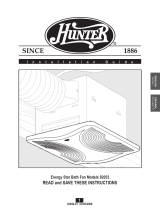
80201 Bath Ventilator with Light
READ and SAVE THESE INSTRUCTIONS
ENGLISH
See page 2
ESPAÑOL
Vea la página 29
FRANCAIS
Voir la page 15
42939-01_2.5.08_Arial.indd 1 2/5/08 1:43:43 PM

42939-01 02/05/2008
2
DISCONNECT ELECTRIC
POWER SUPPLY
AND LOCK OUT
SERVICE PANEL BEFORE
SERVICING UNIT
W A R N I N G
TO REDUCE THE RISK OF FIRE, ELECTRIC SHOCK, OR INJURY TO PERSONS,
OBSERVE THE FOLLOWING:
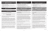
1. For general ventilating use only. Do not use to exhaust
hazardous or explosive materials and vapors.
2. To avoid motor/blower bearing damage and noisy/unbalanced
impellers, keep drywall spray, construction dust, etc. off power unit.
3. DO NOT install this product in a wall. This product is designed
for installation in ceilings up to a 12/12 pitch (45 degrees).
Ductwork must point upward.
4. Pleasereadspecicationlabelonproductforfurtherinformation
and requirements.
PREVENTATIVE MAINTENANCE
A clean fan provides better service. Disconnect the power supply
and clean the fan as listed below.
TO CLEAN GRILLE: Use a mild detergent, such as dishwashing
liquid, and a soft cloth. DO NOT use abrasive cloths, steel wool
pads or scouring powders.
TO CLEAN FAN ASSEMBLY:
Unplug motor/blower cord from recep-
tacle. To remove motor/blower, find the single tab on the motor/blower
(located next to the receptacle). Push up rear motor/blower tab while
pushing out on the side of the housing or insert a screwdriver into the
slot in the housing (next to tab) and twist screwdriver. Gently vacuum
fan, motor/blower and interior of housing.
METAL AND ELECTRICAL PARTS SHOULD NEVER BE IMMERSED
IN WATER.
MAINTENANCE
The motor/blower is permanently lubricated and never needs oiling.
If the motor/blower bearings are making excessive or unusual noises,
replace the motor/blower with the exact service motor/blower. You
should replace the impeller at the same time.
C A U T I O N
W A R N I N G
1. Use this unit only in a manner intended by the manufacturer.
If you have questions, contact the manufacturer.
2. Before servicing or cleaning the unit, switch power off at service
panel and lock the service disconnecting means to prevent
power from being switched on accidentally. When the service
disconnecting means cannot be locked, securely fasten a
prominent warning device, such as a tag, to the service panel.
3. Installation work and electrical wiring must be done by
qualiedperson(s)inaccordancewithallapplicable
codesandstandards,includingre-ratedconstruction.
4. Sufcientairisneededforpropercombustionandexhausting
ofgassesthroughtheue(chimney)offuelburningequipment
to prevent backdrafting. Follow the heating equipment manufac-
turer’s guideline and safety standards,such as those published
by the National Fire Prevention Association (NFPA), and the
American Society for Heating, Refrigeration and Air-Conditioning
Engineers (ASHRAE), and the local code authorities.
5. When cutting or drilling into wall(s) or ceiling, do not damage
electrical wiring or other hidden utilities.
6. Ducted fans must always be vented to the outdoors.
7. If this unit is to be installed over a tub or shower, it must be
marked as appropriate for the application and be connected to a
GFCI (Ground Fault Circuit Interrupter) – protected branch circuit.
8. Never place a switch where it can be reached from a tub or
shower.
9. Installfanatleast5feet(1.52m)abovetheoor.
10. This unit must be grounded.
11. Unit must not be installed in a ceiling thermally insulated to a
value greater than R40.
12. For supply connection, use wires suitable for at least
90˚C(194˚F).
Do Not Install Above
Or Inside This Area
Cooking
Equipment
Floor
45° 45°
COOKING AREA
42939-01_2.5.08_Arial.indd 2 2/5/08 1:43:43 PM

42939-01 02/05/2008
3
H
I
L
M
N
95261-02-000
74508-03-133
96399-01-262
75184-01-133
86812-01-000
O
75734-01-262
x4
*
*
*
NOTE:
Strain relief cable
connector must be
installed. Not Included.
A
B
C
Extra Screws
x2
D
E
F
G
95047-03-000
75864-02-000
03242-07-133
3/8 in. Cable Connector
Motor/Blower
Screws
Light Fixture
J
77522-01
Strain Relief Bracket
K
65219
Strain Relief Bracket Screw
Thumbscrews
Glass Dome
Finial
Housing
Wiring Cover
Wiring Cover Screw
x2
1
Turn off the power source.
Tools Needed. (Not supplied.)
Estimated assembly time: 30 to 60 minutes
Before Installation
Check all the parts.
If damaged, call
1-866-405-3814
for replacements.
2
E
I
Loosen screws.
NOTE: Remove all packing materials before installation.
Included.
42939-01_2.5.08_Arial.indd 3 2/5/08 1:43:45 PM

42939-01 02/05/2008
4
5
4
7
G
8
F
H
E
3
Remove the pre-loaded screw tip covers.
Remove the wiring cover screw.
6
Back out the pre-loaded screw tips until flush
with the side of the housing.
Remove the wiring cover.
Remove packing material.
Remove the motor/blower from the housing.
42939-01_2.5.08_Arial.indd 4 2/5/08 1:43:49 PM

42939-01 02/05/2008
5
9
E
Pop out the first wiring access slug. Use second if needed. Insert the strain relief (not included) into the
housing and secure with washer.
Position the correct depth mark at the bottom edge of the
joist based on the thickness of your sheetrock.
New Construction
10
B
C
Choose Installation Option
For New Construction go to step A1, page 5
For Existing Construction go to step B1, page 8
A1
E
5/8
1/2
5/8
1/2
A2
Screw pre-loaded screws into joist or framing.
42939-01_2.5.08_Arial.indd 5 2/5/08 1:43:51 PM

42939-01 02/05/2008
6
A
3 Pin
2 Pin
Fan Motor
Light
Light
Green
Black
Black
White
Black
Black
White
White
Bare Copper
Ground
A4
Main Switch 1 (AC In)
Switch 2 (AC In)
*Option Fan & Main Light Together
*Option
Connect wires as shown.
A3
Route wires through the strain relief. For supply connection,
use wires suitable for at least 90˚ C (194˚ F).
A6
A5
E
F
G
Install the wiring cover plate. Make sure all
wiring connections are inside the box or under
the wiring cover plate.
Connect 4 in. duct and vent to the outside. Tape joints.
If ducting does not fit securely, an adapter may need
to be purchased.
42939-01_2.5.08_Arial.indd 6 2/5/08 1:43:53 PM

42939-01 02/05/2008
7
A9
I
A10
Reinstall the motor/blower by inserting the tabs and pushing
up into position. Make sure the wires are not pinched
between the motor/blower and the housing.
Secure the motor/blower by tightening the 2 screws. Turn on the power source.
Connect wiring harness. DO NOT ALLOW THE Motor/
blower TO HANG FROM THE WIRING HARNESS.
0
0
0
0
0
0
0
0
A7
0
0
0
0
0
0
0
0
H
A8
ON
OFF
A11
Test the motor/blower. If the motor/blower does not run,
check the plug connection.
A12
C1
Go to step
on page 10
to attach grille.
42939-01_2.5.08_Arial.indd 7 2/5/08 1:43:57 PM

42939-01 02/05/2008
8
EXISTING FAN
B1
E
B2
Existing Construction
B3
2
1
B4
Route wires through the strain relief. For supply connection,
use wires suitable for at least 90˚ C (194˚ F).
Remove an existing fan and check to make sure the open-
ing is large enough to accommodate the new motor/blower
housing (7.25 in. x 7.75 in.).
Move the housing into position above the ceiling.
Attach existing ducting to duct connector. Tape joints.
If ducting does not fit securely,
an adapter may need to be purchased.
E
B5
Install the housing flush with the sheetrock and secure by
tightening the pre-loaded screws into the joist.
42939-01_2.5.08_Arial.indd 8 2/5/08 1:43:59 PM

42939-01 02/05/2008
9
H
B8
H
B9
B10
I
Reinstall the motor/blower by inserting the tabs and
pushing up into position. Make sure the wires are not
pinched between the motor/blower and the housing.
Connect wiring harness. DO NOT ALLOW THE Motor/
blower TO HANG FROM THE WIRING HARNESS.
Secure the motor/blower by tightening the 2 screws.
A
3 Pin
2 Pin
Fan Motor
Light
Light
Green
Black
Black
White
Black
Black
White
White
Bare Copper
Ground
B6
Main Switch 1 (AC In)
Switch 2 (AC In)
*Option Fan & Main Light Together
*Option
Connect wires as shown.
F
B7
G
Install the wiring cover plate.
42939-01_2.5.08_Arial.indd 9 2/5/08 1:44:02 PM

42939-01 02/05/2008
10
ON
OFF
B12
B13
C1
Go to step
on page 10
to attach grille.
B11
Turn on the power source.
L
O
C2
N
M
C1
Attaching the Grille
Remove the thumbscrews. Remove glass dome.
Test the motor/blower. If the motor/blower does not run,
check the plug connection.
42939-01_2.5.08_Arial.indd 10 2/5/08 1:44:05 PM

42939-01 02/05/2008
11
C4
K
C5
J
C6
Remove the strain relief bracket screw.
Position the strain relief bracket under the motor as shown.
Insert the strain relief bracket’s dog-leg tab so that
it hooks over the lip of the motor. Reinstall the
strain relief bracket screw.
C3
L
Connect wiring harness. DO NOT ALLOW THE FIXTURE TO
HANG FROM THE WIRING HARNESS.
C7
L
C8
M
L
Align posts 1, 2, and 3 (stamped into motor/blower housing)
with posts 1, 2, and 3 (stamped into light fixture).
Slide light fixture over posts.
Attach thumbscrews.
WARNING: To reduce the risk of electrical shock,
all 3 thumbscrews MUST be properly installed.
42939-01_2.5.08_Arial.indd 11 2/5/08 1:44:07 PM

42939-01 02/05/2008
12
C9
C10
N
O
C11
Align glass dome and push up.Install 2 Max 60 Watt A15 bulbs (Not Included).
Screw glass dome into position.
42939-01_2.5.08_Arial.indd 12 2/5/08 1:44:09 PM

42939-01 02/05/2008
13
Troubleshooting
Problem: Fan does not come on.
Solution:
•HarborBreezeBathVentilatorsareextremelyquiet.Toconrmthatthefanisrunning,placeyourhandneartheventsto
feel the air movement.
• Turn power on, replace fuse, or reset breaker.
• Check all plug connections to be sure they are secure.
• Check the wiring to make sure it matches the wiring diagram.
Problem: Light does not come on.
Solution:
• Replace the light bulb with a new bulb.
• Turn power on, replace fuse, or reset breaker.
• Check all plug connections to be sure they are secure.
• Check the wiring to make sure it matches the wiring diagram.
Problem: Fan is noisy.
Solution:
• Check and tighten all fasteners.
• Check the glass to make sure it is secure.
•Checktheappertomakesureitmovesfreely.
If you need parts or service assistance, please call 866-405-3814.
42939-01_2.5.08_Arial.indd 13 2/5/08 1:44:09 PM

42939-01 02/05/2008
14
Printed in China
© 2008 Hunter Fan Company
Warranty
Harbor Breeze
Bath Exhaust Fan
LIMITED WARRANTY
The manufacturer makes the following limited warranty to the original user or consumer purchaser of this Harbor Breeze bath
exhaust fan:
IfanypartofyourHarborBreezebathexhaustfan(exceptforglassxturesandlightbulbs)failsatanytimewithinoneyearafterthe
date of sale to you due to a defect in material or workmanship, we will repair or, at our option, replace the defective part free of charge.
After this one-year period, you will be responsible for all parts and labor costs for repairs on the bath exhaust fan except for motor/blow-
er repairs as provided below.
IfyourHarborBreezebathexhaustfanmotor/blowerfailsatanytimewithinveyearsafterthedateofsaletoyouduetoadefectin
material or workmanship, labor and materials to repair the defect will be provided free of charge. If no replacement part can be pro-
vided, we will, at our option, either refund the actual purchase price of your bath exhaust fan or provide a replacement free of charge.
Afterthisve-yearperiod,youwillberesponsibleforallpartsandlaborcostsforrepairsonallpartsofthebathexhaustfan.
IF THE ORIGINAL USER OR CONSUMER PURCHASER CEASES TO OWN THE FAN, THIS WARRANTY AND ANY IMPLIED
WARRANTY WHICH THEN REMAINS IN EFFECT, INCLUDING BUT NOT LIMITED TO ANY IMPLIED WARRANTY OF MERCHANT-
ABILITY OR FITNESS FOR A PARTICULAR PURPOSE, ARE VOIDED. NO WARRANTY, EXPRESS OR IMPLIED, INCLUDING ANY
WARRANTY OF MERCHANTABILITY OR FITNESS FOR A PARTICULAR PURPOSE, IS MADE IN RESPECT OF GLASS FIXTURES
OR LIGHT BULBS OR THE FINISH ON ANY METAL PORTION OF THE BATH EXHAUST FAN.
THIS WARRANTY IS IN LIEU OF ALL OTHER EXPRESS WARRANTIES. THE DURATION OF ANY IMPLIED WARRANTY, INCLUD-
ING, BUT NOT LIMITED TO, ANY IMPLIED WARRANTY OF MERCHANTABILITY OR FITNESS FOR A PARTICULAR PURPOSE, IN
RESPECT TO ANY HARBOR BREEZE BATH EXHAUST FAN MOTOR/BLOWER OR OTHER FAN PART, IS EXPRESSLY LIMITED
TO THE PERIOD OF THE EXPRESS WARRANTY SET FORTH ABOVE FOR SUCH MOTOR/BLOWERS OR OTHER PARTS.
This warranty is voided if your Harbor Breeze bath exhaust fan is not purchased and installed in the U.S.A. This warranty excludes and
does not cover defects, malfunctions or failures of any Harbor Breeze bath exhaust fan which were caused by repairs by persons not
authorizedbyus,useofpartsoraccessoriesnotauthorizedbyus,mishandling,improperinstallation,modicationsordamagetothe
Harbor Breeze bath exhaust fan while in your possession, or unreasonable use, including failure to provide reasonable and necessary
maintenance.
To obtain servicing, contact the Harbor Breeze Service Department at 1-866-405-3814. Please contact us before shipping your bath
exhaust fan to us. If we authorize you to ship it to us, you will be responsible for all insurance and freight or other transportation charges
to our factory or service center. We will return your Harbor Breeze bath exhaust fan freight prepaid. Your Harbor Breeze bath exhaust
fan should be properly packed to avoid damage in transit since we will not be responsible for any such damage. Proof of purchase is
required when requesting warranty service. The purchaser must present the sales receipt or other document that establishes proof of
purchase.
IN NO EVENT SHALL THE MANUFACTURER BE LIABLE FOR CONSEQUENTIAL OR INCIDENTAL DAMAGES.
SOME STATES DO NOT ALLOW LIMITATIONS ON HOW LONG AN IMPLIED WARRANTY LASTS OR THE EXCLUSION OR LIMITA-
TION OF INCIDENTAL OR CONSEQUENTIAL DAMAGES SO THE ABOVE LIMITATION OR EXCLUSIONS MAY NOT APPLY TO
YOU.
THE WARRANTY GIVES YOU SPECIFIC LEGAL RIGHTS AND YOU MAY ALSO HAVE OTHER RIGHTS WHICH VARY FROM STATE
TO STATE.
42939-01_2.5.08_Arial.indd 14 2/5/08 1:44:09 PM

42939-05 02/05/2008
15
G u i d e d ’ i n s t a l l a t i o n
FRANCAIS
Ventilateur de salle de bain 80201 avec lumière
LIRE ET CONSERVER CES CONSIGNES
42939-05_2.5.08_Arial.indd 15 2/5/08 1:45:44 PM

42939-05 02/05/2008
16
DÉCONNECTER L’ALIMENTATION
ÉLECTRIQUE ET VERROUILLER
LE PANNEAU DE SERVICE
AVANT DE FAIRE L’ENTRETIEN
DE L’UNITÉ.
M I S E E N G A R D E
POUR RÉDUIRE LE RISQUE D’INCENDIE, DE DÉCHARGE ÉLECTRIQUE OU DE BLESSURES,
VEUILLEZ SUIVRE LES DIRECTIVES SUIVANTES :
1. Uniquement pour un usage général de ventilation. Ne pas s’en
servir pour ventiler des matériaux ou des vapeurs dangereux
ou explosifs.
2. Pour éviter des dommages au palier du moteur/souffleur et
des turbines bruyantes ou mal équilibrées, protéger le groupe
moteur/souffleur de la peinture au pistolet, la poussière de
construction, etc.
3. NE PAS installer ce produit dans un mur. Ce produit est conçu
pour être installé dans les plafonds avec un angle de 45°, la
gaine doit pointer vers le haut.
4. Veuillez lire l’étiquette des spécifications sur le produit pour des
renseignements et conditions supplémentaires.
AT T E N T I O N
M I S E E N GARDE
1. Utiliser cet appareil seulement de la façon prévue par le
fabricant. Si vous avez des questions, communiquer avec le
fabricant.
2. Avant l’entretien ou le nettoyage de cet appareil, couper le
courant au panneau de service et verrouiller les moyens de
déconnexion pour empêcher que le courant soit remis acci-
dentellement. Si vous ne pouvez pas verrouiller les moyens
de déconnexion, bien attacher un dispositif de mise en garde
visible, comme une étiquette au panneau de service.
3. Une personne qualifiée doit effectuer le travail d’installation
et de câblage électrique conformément à tous les codes et
normes applicables, y compris les codes et normes de la
construction pare-feu.
4. Il faut suffisamment d’air pour une bonne combustion et un bon
échappement des gaz par le conduit (cheminée) de l’équipement
brûlant le combustible pour empêcher un refoulement. Suivre
les directives du fabricant de votre installation de chauffage
ainsi que les normes de sécurité telles que celles publiées par
l’association nationale de protection contre les incendies (NFPA,
National Fire Protection Association), la société américaine des
ingénieurs en chauffage, réfrigération et climatisation (ASHRAE,
American Society for Heating, Refrigeration, and Air Conditioning
Engineers), et les administrations des codes locaux.
5. Ne pas endommager le câblage électrique ou autres équipe-
ments cachés en coupant ou en perçant les murs ou le plafond.
6. Les ventilateurs canalisés doivent toujours disposer d’une
évacuation vers l’extérieur.
7. Si cet appareil doit être installé au dessus d’un bain ou d’une
douche, il doit être identifié comme approprié à cet usage
connecté à un disjoncteur de fuite à la terre.
8. Ne jamais poser un interrupteur qu’on pourrait atteindre
depuis une baignoire ou une douche.
9. Installer le ventilateur à au moins 1,52 (5 pi) au-dessus du
plancher.
10. Il faut mettre cette unité à la terre.
11. Il ne faut pas installer cet appareil dans un plafond ayant une
isolation thermique supérieure à R40.
12. Pour la connexion d’alimentation, utiliser des fils compatibles
avec une température d’au moins 90º C (194º F).
ENTRETIEN PRÉVENTIF
Un ventilateur propre fournit un meilleur service. Couper le courant
et nettoyer le ventilateur comme indiqué ci-dessous.
POUR NETTOYER LA GRILLE ;
Se servir d’un détergent doux,
comme du liquide à vaisselle, et d’un chiffon doux. Ne pas se servir de
chiffons abrasifs, de tampons de laine d’acier ou de poudres à récurer.
POUR NETTOYER L’ENSEMBLE DU VENTILATEUR ;
Débrancher
le cordon du moteur/souffleur de la prise. Pour retirer la plaque du
moteur/souffleur, repérer la languette unique sur la plaque (située près
de la prise). Pousser vers le haut et l’arrière la languette de la plaque
de moteur/souffleur tout en poussant vers l’extérieur le côté du boîtier,
ou insérer un tournevis dans la fente du boîtier (près de la languette)
et faire levier. Passer doucement l’aspirateur sur le ventilateur, le
moteur/souffleur et à l’intérieur du boîtier
IL NE FAUT JAMAIS IMMERGER DANS L’EAU LES PIÈCES
MÉTALLIQUES ET ÉLECTRIQUES.
ENTRETIEN
Le moteur/souffleur est lubrifié en permanence et n’a jamais besoin
d’huile. Si les paliers du moteur/souffleur font un bruit excessif ou inha-
bituel, remplacer le moteur/souffleur avec exactement le même moteur/
souffleur. Vous devriez en même temps remplacer la turbine.
ÉQUIPEMENT DE CUISSON
Ne rien installer
au-dessus ou dans cette aire
Aire de
cuisson
Plancher
45° 45°
42939-05_2.5.08_Arial.indd 16 2/5/08 1:45:45 PM

42939-05 02/05/2008
17
1
2
E
I
H
I
L
M
N
95261-02-000
74508-03-133
96399-01-262
75184-01-133
86812-01-000
O
75734-01-262
x4
*
*
*
NOTA:
Il faut poser un raccord
de câble. Non compris.
A
B
C
Vis supplémentaires
x2
D
E
F
G
95047-03-000
75864-02-000
03242-07-133
Raccord de câble 3/8 po
Moteur/souffleur
Deux vis
Luminaire
J
77522-01
Serre-câble
K
65219
Vis du serre-câble
Lis à serrage à main
Globe de verre
Faîteau
Boîtier
Couvercle du câblage
Vis du couvercle
x2
Couper le courant.
Avant l’installation
Desserrer les vis.
NOTA : Retirer tous les matériaux d’emballage avant l’installation.
Outils nécessaires. (Non fournis)
Temps estimé du montage : De 30 à 60 minutes
Vérier toutes les pièces. Si
certaines sont endommagées,
appeler le 1-866-405-3814 pour
des pièces de rechange.
Compris.
42939-05_2.5.08_Arial.indd 17 2/5/08 1:45:47 PM

42939-05 02/05/2008
18
5
4
7
G
8
F
H
E
3
6
Retirer le moteur/souffleur du boîtier.
Retirer les capuchons du bout des vis pré-installées.
Retirer la vis du couvercle du câblage.
Dévisser les vis pré-installées jusqu’à ce que leur
bout affleure le côté du boîtier.
Retirer le couvercle du câblage.
Retirer les matériaux d’emballage.
42939-05_2.5.08_Arial.indd 18 2/5/08 1:45:50 PM

42939-05 02/05/2008
19
9
E
10
B
C
A1
E
5/8
1/2
5/8
1/2
A2
Défoncer le première pastille d’accès.
En utiliser une seconde si nécessaire.
Introduire le raccord (non compris) dans le boîtier
et le fixer avec une rondelle.
Placer la bonne marque de hauteur sur le bord inférieur de la
solive selon l’épaisseur de votre plaque de gypse.
Nouvelle construction
Visser les vis pré-installées dans la solive ou la structure.
Choisir votre option d’installation
Pour une nouvelle construction – aller à l’étape A1, page 19
Pour une construction existante – aller à l’étape B1, page 22
42939-05_2.5.08_Arial.indd 19 2/5/08 1:45:52 PM

42939-05 02/05/2008
20
A
Moteur du ventilateur
Lumière
Vert
Noir
Noir
Blanc
Noir Lumière
Noir
Blanc
Blanc
Cuivre nu
Prise de terre
A4
Interrupteur principal 1 (entrée CA)
Interrupteur principal 2 (entrée CA)
*Option ventilateur et lumière principale ensemble
*Option
3
broches
2
broches
A3
A6
A5
E
F
G
Installer la plaque de couvercle du câblage. Assurez-vous
que toutes les connexions de câblage sont dans la boîte ou
derrière la plaque de couvercle du câblage.
Raccorder la gaine de 4 po et l’évent à l’extérieur. Jointer
avec du ruban. Si la gaine n’est pas de la bonne dimension,
vous pourriez devoir acheter un adaptateur.
Connecter les fils tel qu’indiqué.
Passer les fils par le raccord. Pour la connexion d’alimenta-
tion, utiliser des fils compatibles avec une température d’au
moins 90º C (194º F).
42939-05_2.5.08_Arial.indd 20 2/5/08 1:45:55 PM
Page is loading ...
Page is loading ...
Page is loading ...
Page is loading ...
Page is loading ...
Page is loading ...
Page is loading ...
Page is loading ...
Page is loading ...
Page is loading ...
Page is loading ...
Page is loading ...
Page is loading ...
Page is loading ...
Page is loading ...
Page is loading ...
Page is loading ...
Page is loading ...
Page is loading ...
Page is loading ...
Page is loading ...
Page is loading ...
/