ETS-Lindgren 3181 User manual
- Category
- Television antennas
- Type
- User manual
This manual is also suitable for

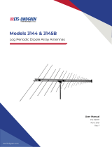
Model 3181 / Model 3183 / Model 3184
End Fed
Mini-Bicon Antenna
User Manual
Model 3181 / Model 3184
Model 3183

ii |
ETS-Lindgren L.P. reserves the right to make changes to any product described
herein in order to improve function, design, or for any other reason. Nothing
contained herein shall constitute ETS-Lindgren L.P. assuming any liability
whatsoever arising out of the application or use of any product or circuit
described herein. ETS-Lindgren L.P. does not convey any license under its
patent rights or the rights of others.
© Copyright 2009–2010 by ETS-Lindgren L.P. All Rights Reserved. No part of
this document may be copied by any means without written permission from
ETS-Lindgren L.P.
Trademarks used in this document: The ETS-Lindgren logo is a trademark of
ETS-Lindgren L.P.
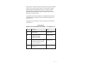
Revision Record
MANUAL,3181 3183 3184 MINI-BICON ANTENNA | Part #399821, Rev. D
Revision Description Date
A Initial Release October, 2009
B Updated data charts in
Typical Data; updated
Mounting Instructions
November, 2009
C Updated 3183 illustrations; added
note about 3183 stem; updated
Physical Specifications
February, 2010
D Updated 3183 photos; updated
3183 data
March, 2010

| iii
Table of Contents
Notes, Cautions, and Warnings .............................................. vii
1.0 Introduction .......................................................................... 9
Model 3181 / Model 3184 .............................................................................. 9
Model 3183 .................................................................................................... 9
Tripod Options ............................................................................................. 10
ETS-Lindgren Product Information Bulletin ................................................. 11
2.0 Maintenance ....................................................................... 13
Annual Calibration ....................................................................................... 13
Replacement and Optional Parts ................................................................. 13
Service Procedures ..................................................................................... 14
3.0 Specifications ..................................................................... 15
Electrical Specifications ............................................................................... 15
Physical Specifications ................................................................................ 15
4.0 Mounting Instructions ....................................................... 17
Using the Antenna Mount Assembly on a 4-TR ........................................... 18
Step 1: Attach Antenna Mount Assembly to 4-TR ............................... 19
Step 2: Mount Antenna to Antenna Mount Assembly .......................... 21
Step 3: Orient to Notch (Model 3183 Only) ......................................... 22
Additional Mounting Options ........................................................................ 23
7-TR and Mast Mounting Options ........................................................ 23
2x2 Boom Mounting Options ............................................................... 25
Weatherizing Kit for Outdoor Testing (3181/3184 Only) .............................. 26
Step 1: Wrap Moldable Plastic Seal Tape ........................................... 27
Step 2: Mold Plastic Seal Tape............................................................ 28
Step 3: Wrap Heavy-Duty All-Weather Vinyl Tape .............................. 28
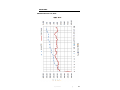
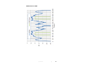
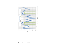
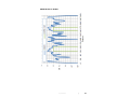
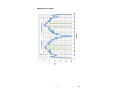
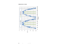
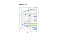
5.0 Typical Data ........................................................................ 29
Model 3181 .................................................................................................. 29
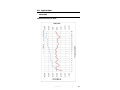
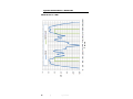
3181 Antenna Factor / Gain................................................................. 29
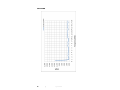
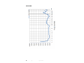
3181 VSWR ......................................................................................... 30
Model 3183 .................................................................................................. 31
3183 Antenna Factor / Gain................................................................. 31
3183 VSWR ......................................................................................... 32

iv |
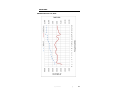
Model 3184 .................................................................................................. 33
3184 Antenna Factor / Gain................................................................. 33
3184 VSWR ......................................................................................... 34
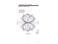
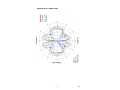
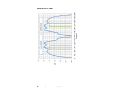
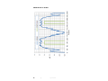
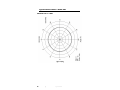
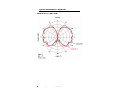
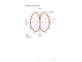
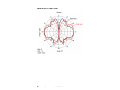
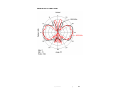
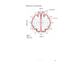
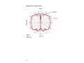
Typical E-Plane Patterns—Model 3181 ....................................................... 35
3181 E-Plane at 500 MHz—1 GHz ...................................................... 35
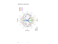
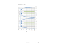
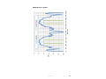
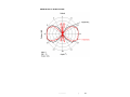
3181 E-Plane at 2 GHz –5 GHz........................................................... 36
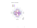
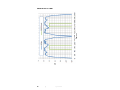
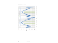
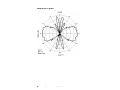
3181 E-Plane at 6 GHz–9 GHz............................................................ 37
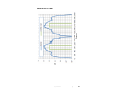
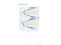
3181 E-Plane at 10 GHz–13 GHz........................................................ 38
3181 E-Plane at 14 GHz–18 GHz........................................................ 39
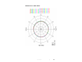
Typical E-Plane Patterns—Model 3183 ....................................................... 40
3183 E-Plane at 1 GHz ........................................................................ 40
3183 E-Plane at 2 GHz ........................................................................ 41
3183 E-Plane at 3 GHz ........................................................................ 42
3183 E-Plane at 4 GHz ........................................................................ 43
3183 E-Plane at 5 GHz ........................................................................ 44
3183 E-Plane at 6 GHz ........................................................................ 45
3183 E-Plane at 7 GHz ........................................................................ 46
3183 E-Plane at 8 GHz ........................................................................ 47
3183 E-Plane at 9 GHz ........................................................................ 48
3183 E-Plane at 10 GHz ...................................................................... 49
3183 E-Plane at 11 GHz ...................................................................... 50
3183 E-Plane at 12 GHz ...................................................................... 51
3183 E-Plane at 13 GHz ...................................................................... 52
3183 E-Plane at 14 GHz ...................................................................... 53
3183 E-Plane at 15 GHz ...................................................................... 54
3183 E-Plane at 16 GHz ...................................................................... 55
3183 E-Plane at 17 GHz ...................................................................... 56
3183 E-Plane at 18 GHz ...................................................................... 57
Typical H-Plane Patterns—Model 3183 ....................................................... 58
3183 H-Plane at 1 GHz........................................................................ 58
3183 H-Plane at 2 GHz–18 GHz ......................................................... 59
Typical E-Plane Patterns—Model 3184 ....................................................... 60
3184 E-Plane at 2 GHz–3 GHz............................................................ 60
3184 E-Plane at 4 GHz–5 GHz............................................................ 61
3184 E-Plane at 6 GHz–7 GHz............................................................ 62
3184 E-Plane at 8 GHz–9 GHz............................................................ 63

| v
3184 E-Plane at 10 GHz–11 GHz........................................................ 64
3184 E-Plane at 12 GHz–13 GHz........................................................ 65
3184 E-Plane at 14 GHz–15 GHz........................................................ 66
3184 E-Plane at 16 GHz–17 GHz........................................................ 67
3184 E-Plane at 18 GHz ...................................................................... 68
Typical H-Plane Patterns—Model 3184 ....................................................... 69
3184 H-Plane at 1 GHz........................................................................ 69
3184 H-Plane at 2 GHz–18 GHz ......................................................... 70
Appendix A: Warranty ............................................................. 71

vi |
This page intentionally left blank.

| vii
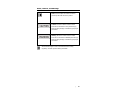
Notes, Cautions, and Warnings
Note: Denotes helpful information intended to
provide tips for better use of the product.
Caution: Denotes a hazard. Failure to follow
instructions could result in minor personal injury
and/or property damage. Included text gives proper
procedures.
Warning: Denotes a hazard. Failure to follow
instructions could result in SEVERE personal injury
and/or property damage. Included text gives proper
procedures.
See the ETS-Lindgren Product Information Bulletin for safety,
regulatory, and other product marking information.

viii |
This page intentionally left blank.

Introduction | 9
1.0 Introduction
The ETS-Lindgren End Fed Mini-Bicons includes these two groups of
broadband omni-directional antennas:
Model 3181 / Model 3184
The Model 3181/3184 is designed for
surveillance, spectrum monitoring, and
shielding tests.
The frequency range for the Model 3181 is
500 MHz to 9 GHz and the frequency range
for the Model 3184 is 1 GHz to 18 GHz.
The Model 3181 performs best up to
9 GHz, but is usable to 18 GHz if
amplification is used. The Model 3184
performs better than the Model 3181 in the
9 GHz to 18 GHz range. Data to 18 GHz is
provided for both antennas.
The radome provides weather protection for
outdoor testing, and a weatherizing kit is
included to protect the antenna connection.
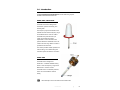
Model 3183
The Model 3183 is designed for
CISPR 16-1-4 chamber validation testing
above 1 GHz. The frequency range for the
Model 3183 is 1 GHz to 18 GHz.
The Model 3183 is not weather protected,
and is not recommended for outdoor
testing.
Never attempt to remove the stem from the Model 3183.

10 | Introduction
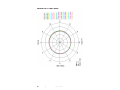
The radiation pattern is omni-directional in the H-plane, allowing the antenna to
receive signals from every direction around the axis. The range covers most
wireless bands worldwide, and is designed for the lowest possible VSWR across
the range of operation. The antenna exhibits better than 2:1 VSWR for most of
the range, and never exceeds 5:1 above 1 GHz.
The small sizes of the antennas enable them to be used for amplifier harmonic
measurements when performing tests per IEC 61000-4-3.
Each antenna is calibrated during manufacturing. The results of the calibration
are tabulated as gain and antenna factor vs. frequency for use in Specification
Compliance Testing. Typical data is provided starting on page 29.
The Model 3181/3183/3184 includes a stinger mount and ships with an antenna
mount assembly for a variety of mounting configurations. For information on the
4-TR, see the next section, Tripod Options; for mounting information, see
Mounting Instructions on page 17.
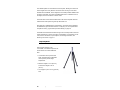
Tripod Options
ETS-Lindgren offers the 4-TR
non-metallic, non-reflective tripod for use
at both indoor and outdoor EMC test
sites.
• Constructed of linen phenolic and
delrin, designed with an adjustable
center post for precise height
adjustments.
• Maximum height is 2.0 m (80.0 in),
and minimum height is 94 cm
(37.0 in).
• Can support up to an 11.8 kg (26.0 lb)
load.

Introduction | 11
ETS-Lindgren Product Information Bulletin
See the ETS-Lindgren Product Information Bulletin included with your shipment
for the following:
• Warranty information
• Safety, regulatory, and other product marking information
• Steps to receive your shipment
• Steps to return a component for service
• ETS-Lindgren calibration service
• ETS-Lindgren contact information

12 | Introduction
This page intentionally left blank.

Maintenance | 13
2.0 Maintenance
Before performing any maintenance, follow
the safety information in the ETS-Lindgren
Product Information Bulletin included with
your shipment.
Maintenance of the Model 3181/3183/3184
is limited to external components such as
cables or connectors.
If you have any questions concerning
maintenance, contact ETS-Lindgren
Customer Service.
Annual Calibration
See the Product Information Bulletin included with your shipment for information
on ETS-Lindgren calibration services.
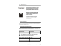
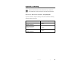
Replacement and Optional Parts
Following are the part numbers for ordering replacement or optional parts for the
Model 3181/3183/3184 End Fed Mini--Bicon Antennas.
Part Description Part Number
Assembly, Antenna Mount 113956
The 114669 Spacer is included in the 113956 Antenna Mount
Assembly, but may also be ordered separately.
Spacer, Extension, Antenna Mount 114669
Moldable Plastic Seal Tape 920381
Heavy-duty All-weather Vinyl Tape 920382
WARRANTY

14 | Maintenance
Service Procedures
For the steps to return a system or system component to ETS-Lindgren for
service, see the Product Information Bulletin included with your shipment.

Specifications | 15
3.0 Specifications
Electrical Specifications
Frequency Range:
• 3181: 500 MHz–9 GHz
• 3183: 1 GHz–18 GHz
• 3184: 1 GHz–18 GHz
VSWR Ratio (Average): 2:1
Maximum Continuous Power: 100 W @ 500 MHz
50 W @ 1 GHz
25 W @ 18 GHz
Impedance: 50 Ω
Connector: SMA female
Physical Specifications
Length:
• 3181/3184: 38.35 cm (15.1 in)
• 3183: 37.3 cm (14.67 in)
Width:
• 3181/3184: 15.25 cm (6.0 in)
• 3183: 7.0 cm (2.76 in)
Stinger Length:
• 3181/3183/3184:
16.0 cm (6.32 in)
Weight:
• 3181: 1.03 kg (2.28 lb)
• 3183: 0.5 kg (1.1 lb)
• 3184: 0.65 kg (1.43 lb)

16 | Specifications
This page intentionally left blank.

Mounting Instructions | 17
4.0 Mounting Instructions
Before connecting any components, follow the
safety information in the ETS-Lindgren
Product Information Bulletin included with your
shipment.
The Model 3181/3183/3184 antennas are
precision measurement devices. Handle your
antenna with care.

18 | Mounting Instructions
Using the Antenna Mount Assembly on a 4-TR
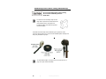
The antenna mount assembly ships with this
larger knob in place of the thumbscrew shown
in the following photos. The larger knob
provides the same functionality but provides
increased usability.
Each Model 3181/3183/3184 End Fed Mini-Bicon Antenna ships with an antenna
mount assembly for a variety of mounting configurations. To use the antenna
mount assembly with an ETS-Lindgren 4-TR Tripod, select the antenna mounting
orientation, attach the antenna mount assembly to the 4-TR, and then attach the
antenna to the antenna mount assembly. Each step is detailed in the following
sections.

Mounting Instructions | 19
STEP 1: ATTACH ANTENNA MOUNT ASSEMBLY TO 4-TR
You may use the antenna mount assembly to mount the Model 3181/3183/3184
in vertical or horizontal orientation.
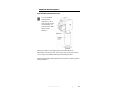
• Vertical orientation:
Attach the extension to
the threaded insert on
the bottom of the
mount and rotate to
tighten into place.
Attach the extension
to the 4-TR using the
threaded insert on the
bottom of the
extension. Turn the
extension to secure
the antenna mount
assembly to the 4-TR.
• Horizontal
orientation: You may
attach the antenna
mount assembly
directly to the 4-TR, or
you may use the
extension to attach it
to the 4-TR.

20 | Mounting Instructions
To direct mount, attach the mount to the 4-TR using the threaded insert on the
side of the mount. Rotate to tighten into place.
To use the extension, attach the extension to the mount using the threaded
insert on the side of the mount, and then turn the extension to tighten. Attach the
extension to the 4-TR using the threaded insert on the bottom of the extension.
Rotate to tighten into place.
Page is loading ...
Page is loading ...
Page is loading ...
Page is loading ...
Page is loading ...
Page is loading ...
Page is loading ...
Page is loading ...
Page is loading ...
Page is loading ...
Page is loading ...
Page is loading ...
Page is loading ...
Page is loading ...
Page is loading ...
Page is loading ...
Page is loading ...
Page is loading ...
Page is loading ...
Page is loading ...
Page is loading ...
Page is loading ...
Page is loading ...
Page is loading ...
Page is loading ...
Page is loading ...
Page is loading ...
Page is loading ...
Page is loading ...
Page is loading ...
Page is loading ...
Page is loading ...
Page is loading ...
Page is loading ...
Page is loading ...
Page is loading ...
Page is loading ...
Page is loading ...
Page is loading ...
Page is loading ...
Page is loading ...
Page is loading ...
Page is loading ...
Page is loading ...
Page is loading ...
Page is loading ...
Page is loading ...
Page is loading ...
Page is loading ...
Page is loading ...
Page is loading ...
-
 1
1
-
 2
2
-
 3
3
-
 4
4
-
 5
5
-
 6
6
-
 7
7
-
 8
8
-
 9
9
-
 10
10
-
 11
11
-
 12
12
-
 13
13
-
 14
14
-
 15
15
-
 16
16
-
 17
17
-
 18
18
-
 19
19
-
 20
20
-
 21
21
-
 22
22
-
 23
23
-
 24
24
-
 25
25
-
 26
26
-
 27
27
-
 28
28
-
 29
29
-
 30
30
-
 31
31
-
 32
32
-
 33
33
-
 34
34
-
 35
35
-
 36
36
-
 37
37
-
 38
38
-
 39
39
-
 40
40
-
 41
41
-
 42
42
-
 43
43
-
 44
44
-
 45
45
-
 46
46
-
 47
47
-
 48
48
-
 49
49
-
 50
50
-
 51
51
-
 52
52
-
 53
53
-
 54
54
-
 55
55
-
 56
56
-
 57
57
-
 58
58
-
 59
59
-
 60
60
-
 61
61
-
 62
62
-
 63
63
-
 64
64
-
 65
65
-
 66
66
-
 67
67
-
 68
68
-
 69
69
-
 70
70
-
 71
71


ETS-Lindgren 3181 User manual
- Category
- Television antennas
- Type
- User manual
- This manual is also suitable for
Ask a question and I''ll find the answer in the document
Finding information in a document is now easier with AI
Related papers
-
 ETS-Lindgren 3104C Owner's manual
-
 ETS-Lindgren 3162-02 Owner's manual
-
 ETS-Lindgren 1052 Owner's manual
-
 ETS-Lindgren 3163 Owner's manual
-
 ETS-Lindgren MAPS Owner's manual
-
 ETS LINDGREN ETS-LINDGREN 3144 Log Periodic Dipole Array Antennas User manual
-
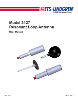 ESCO Technologies ETS LINDGREN 3127 User manual
-
 ETS-Lindgren 3108 Owner's manual
-
 ETS-Lindgren 2070-1/2070-2/2071 Owner's manual
-
 ETS-Lindgren SMART™ 80 Owner's manual


Other documents
-
Lenovo 3243 Hardware Maintenance Manual
-
Lenovo 3243 Maintenance Manual
-
Weston 07-3101-W-A User guide
-
-
Briggs & Stratton 12H800 User manual
-
Esco ETS-Lindgren 3112 User manual
-
 BIO RAD PROTEAN II xi CELL Setup Manual
-
Gyration GYR3101 User manual
-
AT&T IR U-verse User manual
-
Kohler K-3148-NA Installation guide
