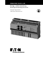
Eaton CEAG SOU CG-S 2 x 4A Mounting And Operating Instructions
- Type
- Mounting And Operating Instructions

CEAG SOU CG-S 2 x 4A
Montage- und Betriebsanleitung
Mounting and Operating Instructions
Zielgruppe: Elektrofachkraft
Target group: Skilled electricians

2
Manual CEAG SOU CG-S 2 x 4A 40071860189 (C) February 2016 www.ceag.de
Inhaltsverzeichnis
SICHERHEITSHINWEISE ........................................3
1 Normenkonformität .........................................3
2 Installation ................................................3
3 Montage ..................................................3
4 Technische Daten ...........................................4
5 Funktionsweise .............................................5
6 Aufbau und Funktion ........................................6
Anzeigeelemente. . . . . . . . . . . . . . . . . . . . . . . . . . . . . . . . . . . . . . . . . . . . . . .6
Bedienelemente
...............................................6
Zusätzliche Features
............................................6
7 Statusausgabe über Blinkcode per Service Pin ..................8
8 Bustechnologie .............................................8
9 Anmelden an das Steuerteil per Suchfunktion ..................9
10 Anmelden an das Steuerteil per Service Pin ...................10
Contents
SAFETY INSTRUCTIONS .......................................3
1 Conformity with standards ...................................3
2 Installation ................................................3
3 Assembly .................................................3
4 Technical Data .............................................4
5 Principle of operation .......................................5
6 Construction and Function ...................................6
Indicators ................................................................. 6
Operation elements
........................................................ 6
Additional Features
........................................................ 6
7 Status output with flash code via service pin ...................8
8 Bustechnology .............................................8
9 Logging on to the control
unit via the search function ..................................9
10 Logging on to the control unit via the service pin ...............10

3
Manual CEAG SOU CG-S 2 x 4A 40071860189 (C) February 2016 www.ceag.de
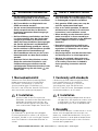
1 Normenkonformität
Konform mit: EMV-Richtlinie 89/336/EWG,
Niederspannungsrichtlinie 73/236/EWG,
EN 50081-1, EN 61000-6-2, EN 50178,
Schaltschwellen gem. EN 60598-2-22,
EN 50171 und VDE 0108. Gemäß DIN EN ISO
9001 entwickelt, gefertigt und geprüft.
2 Installation
Halten Sie die für das Errichten und
Betreiben von elektrischen Be triebs mitteln
geltenden Sicher heits vorschriften, das
Geräte sicher heits gesetz sowie die allge-
mein anerkannten Regeln der Technik ein!
3 Montage
Der Einbauort ist gemäß der einschlägigen
Errich tungsnormen zu wählen (z. B. Unterver-
tei lungen). Hierbei ist auf unzulässige Tempera-
turen am Einbauort während des Betriebs zu
achten.
SICHERHEITSHINWEISE
• Das Stromkreismodul SOU CG-S ist
bestim mungs gemäß in unbeschädigtem
und einwandfreiem Zustand zu betreiben!
• Als Ersatz dürfen nur Originalteile von
CEAG verwendet werden!
• Vor der ersten Inbetriebnahme muss das
Gerät entsprechend den im Abschnitt
Installation genannten Anweisungen ge-
prüft werden!
• Bei Durchführung von Arbeiten am Gerät
ist sicherzustellen, dass das Gerät span-
nungs frei geschaltet ist! Beachten Sie
dabei die unter schiedlichen Ver sorgungen
des Geräts bei Normal- und Notbetrieb.
• Die Protokollführung gemäß der nationa-
len Vorschriften ist durchzuführen (entfällt
bei automatischer Protokollierung)!
• Alle Fremdkörper müssen vor der ersten
Inbetriebnahme aus dem Gerät entfernt
werden!
•
Beachten Sie bei allen Ar beiten an dem
Gerät die nationalen Sicherheits- und
Unfallverhütungsvorschriften und die
nachfolgenden Sicherheitshinweise in der
Betriebsanleitung, die mit einem
ver-
sehen sind!
SAFETY INSTRUCTIONS
• The switching over unit SOU CG-S shall
only be used for its intended purpose and
in undamaged and perfect condition!
• Only genuine CEAG spare parts may be
used for replacement and repair
• Prior to its initial operation, the device
will have to be checked in line with the
instructions (see installation sector)
• When working on the electronic device
make sure that it is disconnected from
the voltage! Pay attention to the different
power supplies in mains or battery
operation.
• Recording in the minutes shall be per-
formed in compliance with the national
regulations (is deleted in case of auto-
matic recording).
• Any foreign object shall be removed from
the device prior to its initial operation!
• Observe the national safety rules and
regulations to prevent accidents as well
as the safety instructions included in
these operating instruction marked
with
1 Conformity with standards
Conforming to: EMC-directive 89/336/EWG,
Low Voltage Directive 73/236/EWG,
EN 50081-1, EN 61000-6-2, EN 50178,
Switching point accd. EN 60598-2-22,
EN 50171 and VDE 0108. Developed, manufac-
tured and tested acc. to ISO 9001.
2 Installation
For the mounting and operation of electri-
cal apparatus, the respective national safe-
ty regulations as well as thegeneral rules
of engineering will haveto be observed.
3 Assembly
The installation location is to be chosen in accor-
dance with the applicable construction stan-
dards (e.g. subdistribution boards). During this
process attention is to be paid to temperatures
outside the permitted range at the installation
location during operation.

4
Manual CEAG SOU CG-S 2 x 4A 40071860189 (C) February 2016 www.ceag.de
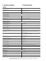
4 Technische Daten 4 Technical Data
Mechanik
Mechanic
Abmessungen (B x H x T)
Dimensions (W x H x D)
178 x 108 x 60 mm
Montage
Installation
Für vertikale Hutschienenmontage
For top hat rail mounting
Schutzart
Degree of protection
IP20
Klimatische Bedingungen
Climatic conditions
Umgebungstemperatur
Ambient temperature
-10 … +55° C
Relative Luftfeuchte
Relative humidity
10 … 95 % keine Betauung
10 … 95 % no condensation
Zulässiger Verschmutzungsgrad
Allowed degree of pollution
2
Elektrische Parameter
Electrical Parameter
Bemessungsspannung Netz
Input voltage Mains
220…240 V AC
Bemessungsspannung Batterie
Input voltage Battery
183…275 V DC
Anzahl der Stromkreise
Number of Circuits
2
Bemessungsstrom Stromkreis
Continuous current rating
4 A pro Stromkreis
4 A per circuit
Gerätesicherung
Input Fusing
16 A Sicherungen 6,3 x 32 mm, max. Kurzschlussstrom 1500 A DC
16 A per circuit, fuses 6.3 x 32 mm, max. high breaking
capacity1500 A DC
Stromkreissicherung
Output Fusing
8 AT pro Stromkreis, Sicherungen 6,3 x 32 mm,
max. Kurzschlussstrom 1500 A DC
8 AT per circuit, fuses 6.3 x 32 mm, max. high breaking
capacity1500 A DC
Max. Einschaltsoßstrom
Maximum Inrush current
250 A pro Stromkreis
250 A per circuit
Bemessungsfrequenz
Permissible mains frequency
50 oder 60 Hz
50 or 60 Hz
Verlustleistung
Over all power loss
≤ 9 W (bei 2 x 4 A)
≤ 9 W (at 2 x 4 A)
Leuchtenadressen
Luminaire addresses
Bis zu 20
Up to 20
Anschlussklemmen
Connecting terminals
Starr: 0,2…4,0 mm
2
mit Aderendhülse: 0,2…2,5 mm
2
Solid: 0.2…4.0 mm
2
, Stranded: 0.2…2.5 mm
2
RS485 Bus - LON
Eingangs- / Ausgangsspannung
Input / Output voltage
≤ 30 V
Polarität
Polarity
Verpolungssicher
Independent
24V +/- Bus / In
Eingangsspannung
Input voltage
22…28,9 V DC
22…28.9 V DC
Eingangsstrom
Input current
≤ 50 mA
Einschaltstrom
Inrush current
≤ 500 mA

5
Manual CEAG SOU CG-S 2 x 4A 40071860189 (C) February 2016 www.ceag.de
5 Funktionsweise
Das Stromkreis Modul speist sich aus zwei
Spannungen. Bei normalen Netzbetrieb
230VAC 50 oder 60Hz und bei Netzausfall
(typische Umschaltzeit 450 ms) über die 216DC
Batteriespannung. Jedes Stromkreismodul
versorgt und überwacht zwei Stromkreise der
Sicherheitsbeleuchtung mit jeweils maximal 20
Sicherheits- und/oder Rettungszeichenleuchten.
Der Mischbetrieb von Sicherheits- und
Rettungs zeichenleuchten in einem Stromkreis
in den Schal tungsarten Bereitschaftslicht,
Dauerlicht und geschaltetes Dauerlicht ohne
die Installation einer separaten Datenleitung
istmöglich.
Die Anbindung der Stromkreis Module an
die Zent ralbatterieanlage erfolgt über den
RS485Bus.
Die Konfiguration (Schaltungsart, Textzuweisung
wie Montageort usw.) der Stromkreis Module
und der angeschlossenen Leuchten erfolgt
über das CU CG-S Steuerteil, welches in der
Zentralbatterieanlage montiert ist. Siehe hierzu
auch Montage- und Bedienungsanleitung ZB-S.
Auf der Front des Stromkreismoduls ist jeder
Stromkreis mit 8AT abgesichert.
Achtung!
Es dürfen nur die von CEAG freigege-
benen Sicherungen eingesetzt wer-
den. Der Einsatz falscher Sicherungen
kann zur Zerstörung des Stromkreis
Modules führen. Das Ansprechen einer
Sicherung wird als Fehler über die LEDs
angezeigt so wie über den RS 485 Bus
dem Steuerteil CU CG-S gemeldet.
Der Betriebszustand (Stromkreis Ein,
Sicherungsdefekt, Überlast, Übertem-
peratur), jedes einzelnen Stromkreises
wird über zwei LEDs angezeigt.
Ein Servicetaster auf der Front
des Stromkreismoduls dient der
Anmeldung des Modules an das
Steuerteil so wie der Fehlerabfrage.
Achtung!
Der Anschluss an das Steuerteil ST-S
ist nicht möglich. Bei Nachrüstung
von SOU-Modulen an ZB-S, muss ein
Steuerteil vom Typ CU CG-S vorhan-
den sein.
5 Principle of operation
The circuit module is fed via two voltages.
With normal mains operation via 230 V AC 50
or 60Hz, and with mains failure (typical switch-
ing duration is 450 ms) via the 216 DC battery
voltage. Each circuit module supplies and moni-
tors two safety lighting circuits, each with a
maximum of 20 safety luminaires and/or escape
sign luminaires. Mixed operation of safety and
escape sign luminaires in one circuit in non-
maintained light, maintained light and switched
maintained light switching modes is possible
without installation of a separate data line.
Connection of the circuit modules to the central
battery system is via the RS 485 bus.
Configuration (switching mode, text assignment,
installation location etc.) of the circuit modules
and connected luminaires is implemented via
the CU CG-S control unit mounted in the central
battery system. See the ZB-S installation and
operating instructions for this.
Each circuit is fused with 8AT on the front of the
circuit module.
Caution!
Only fuses approved by CEAG may
be used. The use of wrong fuses may
cause destruction of the circuit mod-
ule. Responding of a fuse is displayed
as a fault via the LEDs and reported
to the CU CG-S control unit via the RS
485 bus.
The operating state (circuit on, fuse
fault, overload, over-temperature) of
each individual circuit is displayed via
two LEDs.
A service button on the front of the
circuit module is for registration of the
module with the control unit as well as
for the querying of errors.
Caution!
The connection to the control unit
ST-S is not possible. When retrofitting
of SOU modules to ZB-S, a control unit
of the type CU CG-S must be present.

6
Manual CEAG SOU CG-S 2 x 4A 40071860189 (C) February 2016 www.ceag.de
Indicators
ON LED
The LED lights up when the voltage is
present at the output terminals.
Failure LED
The LED lights up when one or more
luminaires are faulty.
Operation elements
Service-PIN
Beside the „Service“ lable there is a button
which must be operated when the system´s
basic program is loaded. The basic program-
ming occurs factory made.
Additional Features
Mixed operation of Maintained light, non-
maintained light and switched maintained light
in one circuit by using of CEAG EVGs/modules
with V-CG-S marking can be programmed with-
out any additional data cable.
Individual monitoring of up to 20 luminaires
per circuit
Separate rental current feed
Easy access fo fuses
Connected rating per circuit
860 W
Inrush current per circuit
250 A/ms
Anzeigeelemente
Leuchtdiode EIN
Die LED leuchtet, wenn Spannung an den
Abgangsklemmen anliegt.
Leuchtdiode Störung
Die LED leuchtet, wenn eine oder mehrere
Leuchten gestört sind.
Bedienelemente
Service-PIN
Neben der Beschriftung „Service“ befin-
det sich ein Taster, der bei der Grundpro-
grammierung der Anlage betätigt werden
muss. Die Grund programmierung erfolgt
bauseits.
Zusätzliche Features
Mischbetrieb von Dauerlicht, Bereitschaftslicht
und geschaltetem Dauerlicht innerhalb eines
Stromkreises bei Verwendung von CEAG EVGs/
Modulen mit V-CG-S Kennzeichnung ohne
zusätzliche Datenleitung frei programmierbar
Einzelüberwachung von max. 20 Leuchten pro
Stromkreis
Separate Mietstromeinspeisung
Sicherungen leicht zugänglich
Anschlussleistung
860 W pro Stromkreis
Einschaltstrom
250 A/ms pro Stromkreis
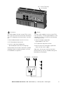
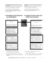
6 Aufbau und Funktion
Sicherungen
Auf der Frontplatte der Stromkreisumschal-
tung befinden sich 2Abgangssicherungen
8AT / 250 V.
Der Nennstrom darf 4 A nicht über-
schreiten! Sicherungsabmessungen:
6,3 mm x 32 mm, sandgefüllt.
Bestell Nr.: 400 71 360 484 / 10 Stck./VE
6 Construction and Function
Fuses
On the front panel of the change-over mod-
ule there are 2 output fuses 8 AT / 250 V.
The nominal current should not exceed 4 A!
Fuse dimensions: 6.3 mm x 32 mm,
sand-filled.
Order no.: 400 71 360 484 / 10 qty./unit
1
3
4
2
1
3
4
2

7
Manual CEAG SOU CG-S 2 x 4A 40071860189 (C) February 2016 www.ceag.de
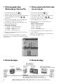
Notes:
The new SOU modules for the system ZB-S
have the ability, also during breakdown of the
controller CU CG-S, to achieve the following
switching functions:
Mains emergency operation
(by breakdown CU CG-S)
DC-operation (by power failure)
back to the mains emergency operation
(return of the mains supply
Admittely, will be no switching functions
performed (e. g. by DLS module) during the
breakdown of controller!
Hinweise:
Die SOU-Module für das System ZB-S sind in
der Lage auch bei Total-Ausfall des Steuerteils
CU CG-S folgende Schaltfunktionen auszufüh-
ren:
Netz-Notbetrieb (bei Ausfall CU CG-S)
DC-Betrieb (bei Netzausfall)
zurück in den Netz-Notbetrieb
(bei Wiederkehr der Netz-Versorgung)
Während des Ausfalls des Steuerteils werden
allerdings keine Schalterfunktionen (z. B von
DLS-Modulen) ausgeführt!
NC = keine Funktion /
no function
1
3
4
2
x2
x1
H3
x2
x1
H2
x2
x1
H1
8AT
L L
AV 230V AC
L L
SV 216V DC

8
Manual CEAG SOU CG-S 2 x 4A 40071860189 (C) February 2016 www.ceag.de
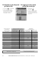
7 Statusausgabe über
Blinkcode per Service Pin
7 Status output with flash code
via service pin
1. Pressing the service pin for at
least 5 s activates the flash code.
2. The display mode is shown with alternating
flashing with the red LEDs , .
3. Following 1 s pause (both LEDs off), display
of the code for circuit 1 starts.
4. Briefly pressing the service button calls
the next fault.
Flash code description:
1 flash = luminaire fault
2 flash = fuse fault
3 flash = overload
4 flash = over-temperature
5. This now proceeds with the second circuit
(from step 3).
If point 4 is not implemented, normal display is
resumed after approx. 30 s.
1. Drücken des Service-PIN für
mind. 5 s aktiviert den Blinkcode.
2. Der Blinkcode wird mit einem abwechselnden
Blinken der beider roten LEDs ,
angezeigt.
3. Nach 1 s Pause (beide LED aus) beginnt die
Anzeige des Codes für Stromkreis 1.
4. Ein kurzes Drücken des Servicetasters ruft
den nächsten Fehler ab.
Blinkcode-Erklärung:
1 x Blinken = Leuchtenstörung
2 x Blinken = Sicherungsfehler
3 x Blinken = Überlast
4 x Blinken = Übertemperatur
5. Jetzt geht es entsprechend mit Stromkreis 2
weiter (ab Schritt 3).
Wenn Punkt 4 nicht durchgeführt wird, dann
wird nach ca. 30 s wieder in die Normalanzeige
gewechselt.
1
32
1
32
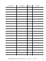
8 Bustechnologie 8 Bustechnology
3
2
1

9
Manual CEAG SOU CG-S 2 x 4A 40071860189 (C) February 2016 www.ceag.de
RS 485-Bus für Kommunikation mit exter-
nen Modulen (DLS/3PH- TLS- oder SOU CG-S
Bus Modul). Der Abschluss wider stand (120 Ω,
0,5 W) ist in den Modulen zuschaltbar.
Zusätzlich gehört ein Widerstand zum
Lieferumfang des Schalt schrankes ZB-S.
Wird nur eine Leitung verlegt, so ist dieser
dortanzubringen.
RS485 bus for communication with external
modules (DLS/3PH-, TLS or SOU CG-S bus
module). The terminating resistor (120, 0.5 W)
can be connected in the modules.
The ZB-S control cabinet also includes a
resistor. This must be mounted in the ZB-S
system if only one cable is laid.
14:45:11 02.01.12
ČČČČČČČČČČČČČČČČČČČČ
Normalbetrieb
Leuchtenstörung
U=245,0V ĀāI=+5,2A
Netz: OK
čččččččččččččččččččč
Erdgeschoss Raum 114
14:45:11 02.01.12
ČČČČČČČČČČČČČČČČČČČČ
SKU 1/4ċ Stromkr.:2ċ
....Ă....ă....Ą....ą
----ĆćććĈĆĆĆĆ-------
Leuchte4.UG Toilette
čččččččččččččččččččč
Erdgeschoss Raum 114
14:45:11 02.01.12
ČČČČČČČČČČČČČČČČČČČČ
SKU 1/4ċ Stromkr.:2ċ
....Ă....ă....Ą....ą
----ĆćććĈĆĆĆĆ-------
Leuchte4.UG Toilette
čččččččččččččččččččč
Erdgeschoss Raum 114
14:45:11 02.01.12
ČČČČČČČČČČČČČČČČČČČČ
NID07 00 00 C2 B9 0
1
BGT: 5 SKU: 8ċ
Typ: SOU CG-S 2x4
Taste OK= Aktivieren
čččččččččččččččččččč
Erdgeschoss Raum 114
14:45:11 02.01.12
ČČČČČČČČČČČČČČČČČČČČ
NID07 00 00 C2
B9 01
Modulnummer: 1ċ
Typ: SOU CG-S 2x4
Taste OK= Aktivieren
čččččččččččččččččččč
Erdgeschoss Raum 114
14:45:11 02.01.12
ČČČČČČČČČČČČČČČČČČČČ
Module 1ċ Circuit:1ċ
Normal Operation
Module name
čččččččččččččččččččč
CEAG AT-S+ Name
14:45:11 02.01.12
ČČČČČČČČČČČČČČČČČČČČ
Modul: 1ċStromkr.:1ċ
Normalbetrieb
Modulname
čččččččččččččččččččč
CEAG AT-S+ Name
14:45:11 02.01.12
ČČČČČČČČČČČČČČČČČČČČ
Betrieb
čččččččččččččččččččč
Erdgeschoss Raum 114
14:45:11 02.01.12
ČČČČČČČČČČČČČČČČČČČČ
SKU deaktivieren
Externe SOU,s suchen
Textzuweisungen
Schalterzuweisungen
čččččččččččččččččččč
Erdgeschoss Raum 114
14:45:11 02.01.12
ČČČČČČČČČČČČČČČČČČČČ
SKU-Aktivierung:
BGT: 5 SKU: 8ċ
Typ: SOU CG-S 2x4
Taste OK= Aktivieren
čččččččččččččččččččč
Erdgeschoss Raum 114
14:45:11 02.01.12
ČČČČČČČČČČČČČČČČČČČČ
Normalbetrieb
Leuchtenstörung
U=245,0V ĀāI=+5,2A
Netz: OK
čččččččččččččččččččč
Erdgeschoss Raum 114
14:45:11 02.01.12
ČČČČČČČČČČČČČČČČČČČČ
SKU 1/4ċ Stromkr.:2ċ
....Ă....ă....Ą....ą
----ĆćććĈĆĆĆĆ-------
Leuchte4.UG Toilette
čččččččččččččččččččč
Erdgeschoss Raum 114
14:45:11 02.01.12
ČČČČČČČČČČČČČČČČČČČČ
SKU 1/4ċ Stromkr.:2ċ
....Ă....ă....Ą....ą
----ĆćććĈĆĆĆĆ-------
Leuchte4.UG Toilette
čččččččččččččččččččč
Erdgeschoss Raum 114
14:45:11 02.01.12
ČČČČČČČČČČČČČČČČČČČČ
NID07 00 00 C2 B9 0
1
BGT: 5 SKU: 8ċ
Typ: SOU CG-S 2x4
Taste OK= Aktivieren
čččččččččččččččččččč
Erdgeschoss Raum 114
14:45:11 02.01.12
ČČČČČČČČČČČČČČČČČČČČ
NID07 00 00 C2
B9 01
Modulnummer: 1ċ
Typ: SOU CG-S 2x4
Taste OK= Aktivieren
čččččččččččččččččččč
Erdgeschoss Raum 114
14:45:11 02.01.12
ČČČČČČČČČČČČČČČČČČČČ
Module 1ċ Circuit:1ċ
Normal Operation
Module name
čččččččččččččččččččč
CEAG AT-S+ Name
14:45:11 02.01.12
ČČČČČČČČČČČČČČČČČČČČ
Modul: 1ċStromkr.:1ċ
Normalbetrieb
Modulname
čččččččččččččččččččč
CEAG AT-S+ Name
14:45:11 02.01.12
ČČČČČČČČČČČČČČČČČČČČ
Betrieb
čččččččččččččččččččč
Erdgeschoss Raum 114
14:45:11 02.01.12
ČČČČČČČČČČČČČČČČČČČČ
SKU deaktivieren
Externe SOU,s suchen
Textzuweisungen
Schalterzuweisungen
čččččččččččččččččččč
Erdgeschoss Raum 114
14:45:11 02.01.12
ČČČČČČČČČČČČČČČČČČČČ
SKU-Aktivierung:
BGT: 5 SKU: 8ċ
Typ: SOU CG-S 2x4
Taste OK= Aktivieren
čččččččččččččččččččč
Erdgeschoss Raum 114
9 Anmelden an das Steuerteil
per Suchfunktion
9 Logging on to the control unit
via the search function
1. Im Untermenü „Stromkreis Setup“
„Externe SOUs suchen“ aktivieren.
2. Einen Baugruppenträgerplatz (5/8 abwärts
zählend von rechts nach links der Baugruppe
zuordnen.
1. In the „Circuit setup“ sub-menu activate
search for external SOUs.
2. Assign a module support slot to the assembly
(5/8 counting downwards from right to left)
14:45:11 02.01.12
ČČČČČČČČČČČČČČČČČČČČ
Normalbetrieb
Leuchtenstörung
U=245,0V ĀāI=+5,2A
Netz: OK
čččččččččččččččččččč
Erdgeschoss Raum 114
14:45:11 02.01.12
ČČČČČČČČČČČČČČČČČČČČ
SKU 1/4ċ Stromkr.:2ċ
....Ă....ă....Ą....ą
----ĆćććĈĆĆĆĆ-------
Leuchte4.UG Toilette
čččččččččččččččččččč
Erdgeschoss Raum 114
14:45:11 02.01.12
ČČČČČČČČČČČČČČČČČČČČ
SKU 1/4ċ Stromkr.:2ċ
....Ă....ă....Ą....ą
----ĆćććĈĆĆĆĆ-------
Leuchte4.UG Toilette
čččččččččččččččččččč
Erdgeschoss Raum 114
14:45:11 02.01.12
ČČČČČČČČČČČČČČČČČČČČ
NID07 00 00 C2 B9 0
1
BGT: 5 SKU: 8ċ
Typ: SOU CG-S 2x4
Taste OK= Aktivieren
čččččččččččččččččččč
Erdgeschoss Raum 114
14:45:11 02.01.12
ČČČČČČČČČČČČČČČČČČČČ
NID07 00 00 C2
B9 01
Modulnummer: 1ċ
Typ: SOU CG-S 2x4
Taste OK= Aktivieren
čččččččččččččččččččč
Erdgeschoss Raum 114
14:45:11 02.01.12
ČČČČČČČČČČČČČČČČČČČČ
Module 1ċ Circuit:1ċ
Normal Operation
Module name
čččččččččččččččččččč
CEAG AT-S+ Name
14:45:11 02.01.12
ČČČČČČČČČČČČČČČČČČČČ
Modul: 1ċStromkr.:1ċ
Normalbetrieb
Modulname
čččččččččččččččččččč
CEAG AT-S+ Name
14:45:11 02.01.12
ČČČČČČČČČČČČČČČČČČČČ
Betrieb
čččččččččččččččččččč
Erdgeschoss Raum 114
14:45:11 02.01.12
ČČČČČČČČČČČČČČČČČČČČ
SKU deaktivieren
Externe SOU,s suchen
Textzuweisungen
Schalterzuweisungen
čččččččččččččččččččč
Erdgeschoss Raum 114
14:45:11 02.01.12
ČČČČČČČČČČČČČČČČČČČČ
SKU-Aktivierung:
BGT: 5 SKU: 8ċ
Typ: SOU CG-S 2x4
Taste OK= Aktivieren
čččččččččččččččččččč
Erdgeschoss Raum 114
14:45:11 02.01.12
ČČČČČČČČČČČČČČČČČČČČ
Normalbetrieb
Leuchtenstörung
U=245,0V ĀāI=+5,2A
Netz: OK
čččččččččččččččččččč
Erdgeschoss Raum 114
14:45:11 02.01.12
ČČČČČČČČČČČČČČČČČČČČ
SKU 1/4ċ Stromkr.:2ċ
....Ă....ă....Ą....ą
----ĆćććĈĆĆĆĆ-------
Leuchte4.UG Toilette
čččččččččččččččččččč
Erdgeschoss Raum 114
14:45:11 02.01.12
ČČČČČČČČČČČČČČČČČČČČ
SKU 1/4ċ Stromkr.:2ċ
....Ă....ă....Ą....ą
----ĆćććĈĆĆĆĆ-------
Leuchte4.UG Toilette
čččččččččččččččččččč
Erdgeschoss Raum 114
14:45:11 02.01.12
ČČČČČČČČČČČČČČČČČČČČ
NID07 00 00 C2 B9 0
1
BGT: 5 SKU: 8ċ
Typ: SOU CG-S 2x4
Taste OK= Aktivieren
čččččččččččččččččččč
Erdgeschoss Raum 114
14:45:11 02.01.12
ČČČČČČČČČČČČČČČČČČČČ
NID07 00 00 C2
B9 01
Modulnummer: 1ċ
Typ: SOU CG-S 2x4
Taste OK= Aktivieren
čččččččččččččččččččč
Erdgeschoss Raum 114
14:45:11 02.01.12
ČČČČČČČČČČČČČČČČČČČČ
Module 1ċ Circuit:1ċ
Normal Operation
Module name
čččččččččččččččččččč
CEAG AT-S+ Name
14:45:11 02.01.12
ČČČČČČČČČČČČČČČČČČČČ
Modul: 1ċStromkr.:1ċ
Normalbetrieb
Modulname
čččččččččččččččččččč
CEAG AT-S+ Name
14:45:11 02.01.12
ČČČČČČČČČČČČČČČČČČČČ
Betrieb
čččččččččččččččččččč
Erdgeschoss Raum 114
14:45:11 02.01.12
ČČČČČČČČČČČČČČČČČČČČ
SKU deaktivieren
Externe SOU,s suchen
Textzuweisungen
Schalterzuweisungen
čččččččččččččččččččč
Erdgeschoss Raum 114
14:45:11 02.01.12
ČČČČČČČČČČČČČČČČČČČČ
SKU-Aktivierung:
BGT: 5 SKU: 8ċ
Typ: SOU CG-S 2x4
Taste OK= Aktivieren
čččččččččččččččččččč
Erdgeschoss Raum 114
14:45:11 02.01.12
ČČČČČČČČČČČČČČČČČČČČ
NID07 00 00 C2 B9 0
1
Modulenumber: 1ċ
Type: SOU CG-S 2x4
Key OK= deaktivate
čččččččččččččččččččč
14:45:11 02.01.12
ČČČČČČČČČČČČČČČČČČČČ
Operation
čččččččččččččččččččč
14:45:11 02.01.12
ČČČČČČČČČČČČČČČČČČČČ
deaktivate module
Search ext. modules
Text-assignment
DLS/TLS-Assignment
čččččččččččččččččččč
14:45:11 02.01.12
ČČČČČČČČČČČČČČČČČČČČ
deaktivate module:
Subrack: 5 SKU: 8ċ
Type: SOU CG-S 2x4
Key OK= deaktivate
čččččččččččččččččččč
Basement Floor 114
Basement Floor 114
Basement Floor 114
Basement Floor 114
14:45:11 02.01.12
ČČČČČČČČČČČČČČČČČČČČ
NID07 00 00 C2 B9 0
1
Modulenumber: 1ċ
Type: SOU CG-S 2x4
Key OK= deaktivate
čččččččččččččččččččč
14:45:11 02.01.12
ČČČČČČČČČČČČČČČČČČČČ
Operation
čččččččččččččččččččč
14:45:11 02.01.12
ČČČČČČČČČČČČČČČČČČČČ
deaktivate module
Search ext. modules
Text-assignment
DLS/TLS-Assignment
čččččččččččččččččččč
14:45:11 02.01.12
ČČČČČČČČČČČČČČČČČČČČ
deaktivate module:
Subrack: 5 SKU: 8ċ
Type: SOU CG-S 2x4
Key OK= deaktivate
čččččččččččččččččččč
Basement Floor 114
Basement Floor 114
Basement Floor 114
Basement Floor 114

10
Manual CEAG SOU CG-S 2 x 4A 40071860189 (C) February 2016 www.ceag.de
1
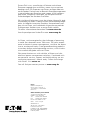
10 Anmelden an das Steuerteil
per Service Pin
1. Service Pin kurz betätigen.
2. Einen Baugruppenträger -
platz 5/8 abwärts zählend
von rechts nach links der
Baugruppe zuordnen.
1
10 Logging on to the control
unit via the service pin
1. Briefly press the
service pin.
2. Assign a module support
slot to the assembly 5/8
counting downwards from
right to left.
1
Neuron ID Nummer
SOU Modul
Zuordnung Steuerteil CU CG-S
Assignment CU CG-S control unit
Montageort
Installation location
Neuron ID number
SOU module
Baugruppenträger
Module support
Steckplatz
Slot
Gebäude/Geschoss
Building/floor
Raumnummer
Room number
NID07 00 00C2 B9 01 5 8 1/EG 1105
NID07 00 00C2 B9 02 5 7 1/EG 1105
NID07 00 00C2 B9 03 5 6 1/EG 1105
NID07 00 00C2 B9 04 5 5 1/EG 1105
NID07 00 00C2 B9 05 5 4 1/EG 1105
NID07 00 00C2 B9 06 5 3 1/EG 1106
NID07 00 00C2 B9 07 5 2 1/EG 1106
NID07 00 00C2 B9 08 5 1 1/EG 1106
NID07 00 00C2 B9 09 4 8 1/EG 1106
NID07 00 00C2 B9 10 4 7 1/EG 1106
NID07 00 00C2 B9 11 4 6 1/EG 1107
NID07 00 00C2 B9 12 4 5 1/EG 1107
NID07 00 00C2 B9 13 4 4 1/EG 1107
NID07 00 00C2 B9 14 4 3 1/EG 1107
NID07 00 00C2 B9 15 4 2 1/EG 1107
Vor der Konfiguration notieren
Note before the configuration
Während der Konfiguration zuordnen
Assign during the configuration

11
Manual CEAG SOU CG-S 2 x 4A 40071860189 (C) February 2016 www.ceag.de
Modul / Module
Neuron ID
Stromkreisname /
Circuit name
Modul-Nr. /
Module No.
Bemerkung /
Remark

Eatons Ziel ist es, zuverlässige, effiziente und sichere
Stromversorgung dann zu bieten, wenn sie am meisten
benötigt wird. Die Experten von Eaton verfügen über ein
umfassendes Fachwissen im Bereich Energiemanagement
in verschiedensten Branchen und sorgen so für kundens-
pezifische, integrierte Lösungen, um anspruchsvollste
Anforderungen der Kunden zu erfüllen.
Wir sind darauf fokussiert, stets die richtige Lösung für jede
Anwendung zu finden. Dabei erwarten Entscheidungsträger
mehr als lediglich innovative Produkte. Unternehmen wen-
den sich an Eaton, weil individuelle Unterstützung und der
Erfolg unserer Kunden stets an erster Stelle stehen.
Für mehr Informationen besuchen Sie
www.eaton.de.
Ihre Ansprechpartner finden Sie unter
www.ceag.de.
At Eaton, we’re energized by the challenge of powering
a world that demands more. With over 100 years experi-
ence in electrical power management, we have the exper-
tise to see beyond today. From groundbreaking products
to turnkey design and engineering services, critical indus-
tries around the globe count on Eaton.
We power businesses with reliable, efficient and safe
electrical power management solutions. Combined with
our personal service, support and bold thinking, we are
answering tomorrow’s needs today. Follow the charge
with Eaton. Visit
eaton.eu.
You will find your contact partner at www.ceag.de.
Eaton
EMEA Headquarters
Route de la Longeraie 7
1110 Morges, Switzerland
Eaton.eu
CEAG Notlichtsysteme GmbH
Senator-Schwartz-Ring 26
59494 Soest, Germany
Tel.: +49 (0) 2921 69-870
Fax: +49 (0) 2921 69-617
E-mail: [email protected]
Web: www.ceag.de
© 2016 Eaton
Alle Rechte vorbehalten
Printed in Germany
Publikations-Nr. IB451030ML
Bestell-Nr. 40071860189 (C)
February 2016
-
 1
1
-
 2
2
-
 3
3
-
 4
4
-
 5
5
-
 6
6
-
 7
7
-
 8
8
-
 9
9
-
 10
10
-
 11
11
-
 12
12


Eaton CEAG SOU CG-S 2 x 4A Mounting And Operating Instructions
- Type
- Mounting And Operating Instructions
Ask a question and I''ll find the answer in the document
Finding information in a document is now easier with AI
in other languages
- Deutsch: Eaton CEAG SOU CG-S 2 x 4A
Related papers
-
Eaton CEAG 3-PM-IO Mounting And Operating Instructions
-
-
-
-
-
-
-
Eaton V-CG-SE 4-400W Owner's manual
-
-
Other documents
-
Renkforce 622412 Owner's manual
-
Samsung SAMSUNG ST10 User manual
-
Bosch RM2-DP12 Description
-
Danfoss Electronic Oil Burner Controls BHO 71A.10 Installation guide
-
Trane MWC524 Installation & Operation Manual
-
iKey DT-102-SS-NI Technical Drawing
-
Olympus 137578 User manual
-
-
Cooper CEAG SL 71811 CG Line Operating Instructions Manual
-