Heath Zenith Secure Home SH-5408 User manual
- Category
- Motion detectors
- Type
- User manual
This manual is also suitable for

© 2008 HeathCo LLC 598-1156-03
Model SH-5408
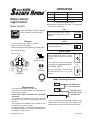
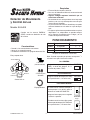
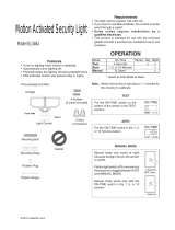
Features
• Turns on lighting when motion is detected.
• Automatically turns lighting off.
• Photocell keeps the lighting off during daylight hours.
Requirements
• The light control requires 120-volts AC.
• If you want to use Manual Mode, the control must be
wired through a switch.
• Some codes require installation by a qualified
electrician.
• This product is intended for use with the enclosed
gasket and with a junction box marked for use in wet
locations.
• The backplate has knockouts so the sensor can be
mounted on most junction boxes.
• In some applications a universal adaptor plate may
be needed. Adaptors are available at home centers
and electrical supply stores.
Cover
Plate
Light Control
Lamp Holders
Sensor
2 Wire
Connectors
Gasket
4 Mounting
Screws (2 sizes)
This package includes:
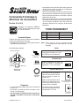
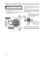
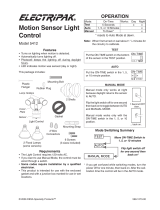
OPERATION
* resets to Auto Mode at dawn.
TEST
10 5 1 TEST
ON-TIME
Put the ON-TIME switch on the
bottom of the sensor in the TEST
position.
MANUAL MODE
ON-TIME
10 5 1 TEST
... back on.
AUTO
1 Second OFF
then...
Move ON-TIME Switch
to 1, 5, or 10 minutes
Mode Switching Summary
Flip light switch
off for one second
then back on*
MANUAL MODE
AUTO
TEST
Note: When first turned on wait about 1
1
/
2
minutes for
the circuitry to calibrate.
Manual mode only works at night
because daylight returns the sensor
to AUTO.
Flip the light switch off for one second
then back on to toggle between AUTO
and MANUAL MODE.
Manual mode works only with the
ON-TIME switch in the 1, 5, or 10
position.
* If you get confused while switching modes, turn the
power off for one minute, then back on. After the cali-
bration time the control will be in the AUTO mode.
Put the ON-TIME switch in the 1, 5,
or 10 minute position.
Mode: On-Time: Works: Day Night
Test
5 Sec x x
Normal
1, 5, 10 min. x
Manual
Until Dawn* x
Motion Sensor
Light Control
Meets the ENERGY STAR
®
guidelines
when used with 120 W Max bulbs.

2
598-1156-03
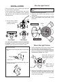
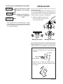
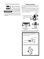
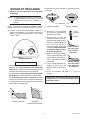
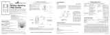
Wire the Light Control
For eave mount only:
Mount the Light Control
❒ Rotate the sensor head towards the clamp screw
joint.
❒ Then rotate the sensor head clockwise 180° so the
controls face down.
Control Switch
Joint Clamp
INSTALLATION
For easy installation, select an existing light operated
by a wall switch for replacement.
For best performance, mount the fixture about 8 feet
(2.4 m) above the ground. NOTE:
If fixture is mounted
higher than 8 ft. (2.4 m), aiming the sensor down will reduce
coverage distance.
For under eave installation, the sensor head must
be rotated as shown in the next two steps for proper
operation and to avoid the risk of electrical shock.
❒ Align the light control cover plate and the junction
box holes. Secure with the mounting screws.
❒ If not installed on a weatherproof box or if an adaptor
plate (not included) was used, caulk the wall plate
and mounting surface with silicone.
❒ Adjust the lamp holders by loosening the lock nuts
but do not rotate the lamp holders more than 180°
from the factory setting. When screwing in the flood-
lamps, do not overtighten.
Keep lamps at
least 1" (25 mm)
from the sensor.
Avoid water damage and
electrical shock - keep lamp
holders below horizontal.
Lock nuts
Black to Black
White to White
Gasket
❒ Drill the holes needed
to mount the backplate
to the junction box.
❒ Remove the existing light fixture.
❒ Route the light control’s wires through the large
gasket hole.
❒ Connect the junction box wires to the light control
wires. Twist together and secure with a wire
connector.
WARNING: Turn power off at the fuse or circuit
breaker.
Eave Mount Wall Mount

3
598-1156-03
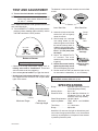
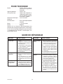
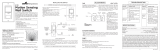
ON - TIME
10
5
1
TEST
MIN MAX
SENS
Bottom of Sensor
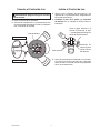
TEST AND ADJUSTMENT
NOTE: Sensor has a 1
1
/
2
minute warm up period
before it will detect motion. When first turned
on, wait 1
1
/
2
minutes.
❒ Turn on the circuit breaker and light switch.
Motion
Motion
The detector is most sensitive to motion across its field
of view.
Maximum Range Maximum
Coverage Angle
Avoid aiming the control at:
• Objects that change temperature rapidly, such as
heating vents and air conditioners. These heat
sources could cause false triggering.
• Areas where pets or traffic may trigger the control.
• Nearby large, light-colored objects reflecting light
may trigger the shut-off feature. Do not point other
lights at the sensor.
60 ft.
(18.3 m)
8 ft.
(2.4 m)
110°
Least Sensitive Most Sensitive
Sensor
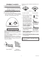
❒ Loosen the clamp screw in the
sensor ball joint and gently
rotate the sensor.
❒ Walk through the coverage
area noting where you are
when the lights turn on. Move
the sensor head up, down, or
sideways to change the cover-
age area. Keep the sensor at
least 1" (2.5 cm) away from
the lamps.
❒ Adjust the SENSITIVITY
as needed. Too much
sensitivity may increase false
triggering.
❒ Secure the sensor head by
tightening the clamp screw.
Do not overtighten the screw.
❒ Set the amount of TIME you want the lights to stay
on after motion is detected (1, 5, or 10 minutes).
SPECIFICATIONS
Range . . . . . . . . . . . . Up to 60 ft. (18.3 m) [varies with
surrounding temperature].
Sensing Angle . . . . . . Up to 110°
Electrical Load . . . . . . Up to 300 Watt Maximum In-
candescent [Up to 150 Watt
maximum each lamp holder.]
Power Requirements . 120 VAC, 60 Hz
Operating Modes . . . . TEST, AUTO and MANUAL
MODE
Time Delay . . . . . . . . 1, 5, 10 minutes
Range . . . . . . . . . . . . Adjustable
HeathCo LLC reserves the right to discontinue prod-
ucts and to change specifications at any time without
incurring any obligation to incorporate new features
in products previously sold.
Warning - Risk of fire. Do not aim the lamps at a
combustible surface within 3 ft. (1 m).
NOTE: Meets the ENERGY STAR
®
guidelines when used
with 120 W Max bulbs.
❒
Turn the SENSITIVITY (SENS) control to the
medium
position
(halfway between MIN and MAX)
and the
ON-TIME control to the TEST position.
Clamp
Screw
Ball
Joint
Aim Sensor
Down for Short
Coverage
Aim Sensor
Higher for Long
Coverage

4
598-1156-03
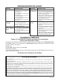
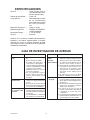
SYMPTOM
Lights will not come
on.
Lights come on
in daylight.
Lights come on
for no apparent
reason.
POSSIBLE CAUSE
1. Light switch is turned off.
2. Flood li ght is loos e or
burned out.
3. Fuse is blown or circuit breaker
is turned off.
4. Daylight turn-off is in effect
(re-
check after dark).
5. Incorrect circuit wiring, if this is a
new installation.
6. Re-aim the sensor to cover de
-
sired area.
1. Light control may be installed in
a relatively dark location.
2. Light control is in Test.
(Set control switch to an
ON-TIME position).
1. Light control may be sensing
small animals or automobile traf-
fic (re-aim sensor).
2. Sensitivity is set too high. (Reduce
sensitivity.)
SYMPTOM
Lights stay on
continuously.
Lights flash on
and off.
POSSIBLE CAUSE
1. A flood lamp is positioned too close to
the sensor or pointed at nearby objects
that cause heat to trigger the sensor.
(Reposition the lamp away from the
sensor or nearby objects).
2. Light control is pointed toward a heat
source like an air vent, dryer vent, or
brightly-painted heat-reflective sur-
face. (Reposition sensor).
3. Light control is in Manual Mode.
(Switch
to Auto.)
1. Heat or light from the lamps may be
turning the light control on and off.
(Reposition the lamps away from the
sensor).
2. Heat being reflected from other objects
may be affecting the sensor. (Reposi-
tion sensor).
3. Light control is in the Test mode and
warming up. (Flashing is normal under
these conditions).
4. Light may be leaking through the flood
-
lamp reflectors. (Replace the lamps with
new high quality PAR 38 lamps).
TROUBLESHOOTING GUIDE
TECHNICAL SERVICE
Please call 1-800-858-8501 (English speaking only) for assistance
before returning product to store.
If you experience a problem, follow this guide. You may also want to visit our Web site at: www.hzsupport.com.
If the problem persists, call* for assistance at 1-800-858-8501 (English speaking only), 7:30 AM to 4:30 PM
CST (M-F). You may also write* to:
HeathCo LLC
P.O. Box 90004, Bowling Green, KY 42102-9004
ATTN: Technical Service
* If contacting Technical Service, please have the following information available: Model Number, Date of Pur-
chase, and Place of Purchase.
No Service Parts Available for this Product
TWO YEAR LIMITED WARRANTY
This is a “Limited Warranty” which gives you specific legal rights. You may also have other rights which vary from state to state or
province to province.
For a period of two years from the date of purchase, any malfunction caused by factory defective parts or workmanship will be cor-
rected at no charge to you.
Not Covered - Repair service, adjustment and calibration due to misuse, abuse or negligence, light bulbs, batteries, and other expend-
able items are not covered by this warranty. Unauthorized service or modification of the product or of any furnished component will
void this warranty in its entirety. This warranty does not include reimbursement for inconvenience, installation, setup time, loss of use,
unauthorized service, or return shipping charges.
This warranty covers only HeathCo LLC assembled products and is not extended to other equipment and components that a customer
uses in conjunction with our products.
THIS WARRANTY IS EXPRESSLY IN LIEU OF ALL OTHER WARRANTIES, EXPRESS OR IMPLIED, INCLUDING ANY WARRANTY,
REPRESENTATION OR CONDITION OF MERCHANT ABILITY OR THAT THE PRODUCTS ARE FIT FOR ANY PARTICULAR PUR-
POSE OR USE, AND SPECIFICALLY IN LIEU OF ALL SPECIAL, INDIRECT, INCIDENTAL, OR CONSEQUENTIAL DAMAGES.
REPAIR OR REPLACEMENT SHALL BE THE SOLE REMEDY OF THE CUSTOMER AND THERE SHALL BE NO LIABILITY ON THE
PART OF HEATHCO LLC FOR ANY SPECIAL, INDIRECT, INCIDENTAL, OR CONSEQUENTIAL DAMAGES, INCLUDING BUT NOT
LIMITED TO ANY LOSS OF BUSINESS OR PROFITS, WHETHER OR NOT FORESEEABLE. Some states or provinces do not allow
the exclusion or limitation of incidental or consequential damages, so the above limitation or exclusion may not apply to you. Please
keep your dated sales receipt, it is required for all warranty requests.
Page is loading ...
Page is loading ...
Page is loading ...
Page is loading ...
Page is loading ...
Page is loading ...
Page is loading ...
Page is loading ...
Page is loading ...
Page is loading ...
Page is loading ...
Page is loading ...
-
 1
1
-
 2
2
-
 3
3
-
 4
4
-
 5
5
-
 6
6
-
 7
7
-
 8
8
-
 9
9
-
 10
10
-
 11
11
-
 12
12
-
 13
13
-
 14
14
-
 15
15
-
 16
16


Heath Zenith Secure Home SH-5408 User manual
- Category
- Motion detectors
- Type
- User manual
- This manual is also suitable for
Ask a question and I''ll find the answer in the document
Finding information in a document is now easier with AI
in other languages
Related papers
-
Heath Zenith Home Safety Product BL-1100 User manual
-
-
Heath Zenith Motion Sensor Light Control SH-5411 User manual
-
-
-
-
-
-
-
Other documents
-
Zenith DualBrite 5597 User manual
-
 Electripak 5412 User manual
-
Secure Home SH-5412 User manual
-
Lithonia Lighting OFLR 6LC 120 MO BZ User manual
-
Desa SH-5710 User manual
-
-
 Cooper Wiring Devices 6105 User manual
-
 Cooper Wiring Devices 6109 User manual
-
 Utilitech Motion Sensing Security Light UT-9250-WH Owner's manual
-
 AWSENS SL5662-BZ User manual


