Laserliner CompactLine-Laser G360 Set Owner's manual
- Category
- Laser levels
- Type
- Owner's manual

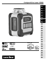
CompactLine-Laser G360
02
12
22
32
42
52
DE
EN
NL
DA
FR
ES
IT
PL
FI
PT
SV
NO
TR
RU
UK
CS
ET
RO
BG
EL
SL
HU
SK
HR
Laser
515 nm
1H360° 1V
S
62
72
Page is loading ...
Page is loading ...
Page is loading ...
Page is loading ...
Page is loading ...
Page is loading ...
Page is loading ...
Page is loading ...
Page is loading ...
Page is loading ...

12
Completely read through the operating instructions, the „Warranty and
Additional Information“ booklet as well as the latest information under
the internet link at the end of these instructions. Follow the instructions
they contain. This document must be kept in a safe place and if the
laser device is passed on, this document must be passed on with it.
!
Function / Application
Green 360° line laser with horizontal laser circle, vertical line
and slope function
– The horizontal laser line creates a continuous 360° laser line with the
vertical lines aligned perpendicular to it. Ideal for almost any alignment job.
– Individually switchable laser lines
– Additional slope function to align angled surfaces
– Bluetooth
®
* interface for remote control of the device
General safety instructions
– The device must only be used in accordance with its intendedpurpose
and within the scope of the specications.
– The measuring tools and accessories are not toys. Keep out of reach
of children.
– Modications or changes to the device are not permitted, this will otherwise
invalidate the approval and safety specications.
– Do not expose the device to mechanical stress, extreme temperatures,
moisture or signicant vibration.
– The device must no longer be used if one or more of its functions fail or the
battery charge is weak.
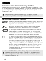
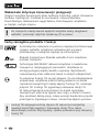
Laser radiation!
Do not stare into the beam!
Class 2 laser < 1 mW · 515 nm
EN 60825-1:2014/AC:2017
Safety instructions
Using class 2 lasers
– Attention: Do not look into the direct or reected beam.
– Do not point the laser beam towards persons.
EN

CompactLine-Laser G360
13
Safety instructions
Dealing with electromagnetic radiation
Safety instructions
Dealing with RF radiation
– The measuring device is equipped with a wireless interface.
– The measuring device complies with electromagnetic compatibility
and wireless radiation regulations and limits in accordance with
the RED 2014/53/EU.
– Umarex GmbH & Co. KG hereby declares that the CompactLine-Laser G360
radio equipment complies with the essential requirements and other
provisions of the European Radio Equipment Directive 2014/53/EU (RED).
The EU Declaration of Conformity can be found in its entirety at the
following address: http://laserliner.com/info?an=AIU
– The measuring device complies with electromagnetic compatibility
regulations and limits in accordance with the EMC Directive 2014/30/EU
which is covered by the Radio Equipment Directive 2014/53/EU.
– Local operating restrictions – for example, in hospitals, aircraft, petrol
stations or in the vicinity of people with pacemakers – may apply.
Electronic devices can potentially cause hazards or interference or
be subject to hazards or interference.
– The measuring accuracy may be affected when working close to high
voltages or high electromagnetic alternating elds.
– If a person‘s eyes are exposed to class 2 laser radiation, they should shut
their eyes and immediately move away from the beam.
– Under no circumstances should optical instruments (magnifying glass,
microscope, binoculars) be used to look at the laser beam or reections.
– Do not use the laser at eye level (1.40 … 1.90 m)
– Reective, specular or shiny surfaces must be covered whilst laser devices
are in operation.
– In public areas shield off the laser beam with barriers and partitions
wherever possible and identify the laser area with warning signs.
EN

14
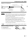
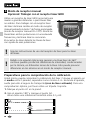
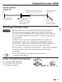
When transporting, always switch off all lasers, secure pendulum
and push the slide switch (3) to the right.
!
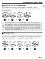
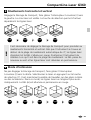
Special product features
Automatic alignment of the device with a magnetically
dampened pendulum system. The device is brought into
initial position and aligns itself autonomously.
Transport LOCK: The device is protected with a pendelum lock
during transport.
GRX-READY technology enables line lasers to be used even
in unfavourable light conditions.The laser lines pulsate at
a high frequency and this can be picked up by special laser
receiversover long distances.
Information on maintenance and care
Clean all components with a damp cloth and do not use cleaning agents,
scouring agents and solvents. Remove the battery(ies) before storing for
longer periods. Store the device in a clean and dry place.
EN
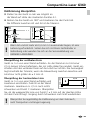
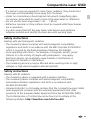
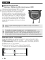
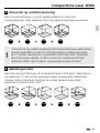
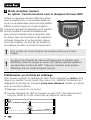
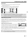
The tilt function is not active following switch-on. Once the
device has been set up, press the tilt button to activate the tilt
function, enabling you to protect the laser from changes in
position caused by the device being disturbed by external
factors. The tilt LED flashes to indicate that the tilt function is
active. If the position of the laser was shifted through external
factors, a signal sounds, the laser flashes and the tilt LED
lights up continuously. Press the tilt button twice to continue.
Erroneous and inaccurate measurements are thus prevented
simply and reliably.
The tilt function does not activate monitoring until 20 seconds after the
laser has been fully levelled (set-up phase). The tilt LED flashes every
second during the set-up phase, and flashes rapidly when tilt is active.
!

CompactLine-Laser G360
15
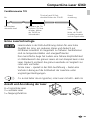
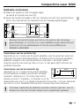
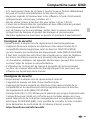
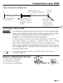
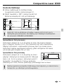
On
External
influence
Automatic level
set-up phase
Enabling the tilt
function: press the
tilt button; the tilt
LED flashes every
second.
The
laser
flashes, the tilt LED
lights up continuously
and a signal sounds.
How the tilt function works
Green laser technology
Laser modules in DLD design stand for high line quality as well
as a clean and clear and therefore easily visible line image.
Unlike previous generations they are more temperature-stable
and energy efficient.
Furthermore, the human eye has a higher sensitivity to the
wave range of the green laser than the red laser, for example.
This makes the green laser diode appear much brighter than
the red one.
Green lasers, especially in the DLD design, thus offer advantages
with regards to how visible the laser line is under unfavourable
conditions.
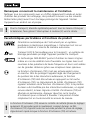
Approx. 6 times brighter than a typical red laser with 630 - 660 nm
Number and direction
of the lasers
H = horizontal laser
V = vertical laser
S = slope function
S
1H360° 1V
EN
Tilt active after 20 seconds,
rapid flashing of the tilt LED.

16
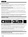
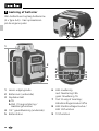
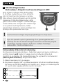
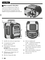
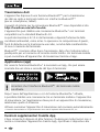
1
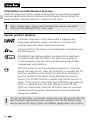
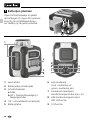
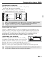
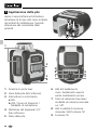
Inserting batteries
Open the battery compartment and
insert batteries (4 x type AA) according
to the symbols. Be sure to pay
attention to polarity.
1
2
4
a
b
3
LED levelling
red: levelling off
green: levelling on
Laser line selection button;
Hand receiver mode on / off
LED hand receiver mode /
LED tilt function
Tilt function
Laser output windows
Battery compartment (bottom)
Slide switch
a ON
b OFF / Transport lock /
Slope mode
1/4” tripod threads (bottom)
Battery status
6
7
8
9
1
2
3
4
5
6
7
5
8
9
EN
+
–
–
+

CompactLine-Laser G360
17
LASER LASER LASER LASER
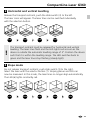
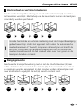
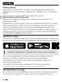
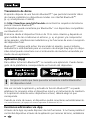
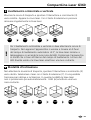
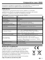
2
Horizontal and vertical levelling
Release the transport restraint, push the slide switch (3) to the left.
The laser cross will appear. The laser lines can be switched individually
with the selection button.
The transport restraint must be released for horizontal and vertical
levelling. The laser lines flash and the LED lights red as soon as the
device is outside the automatic levelling range of 3°. Position the device
such that it is within the levelling range. The LED switches back to
green and the laser lines stop flashing (steady light).
!
3
Slope mode
Do not release transport restraint, push slide switch (3) to the right.
Select the laser with the selector button (7). Sloping planes and tilts can
now be measured. In this mode, the laser lines no longer align automatically.
The LED (6) lights constantly red.
LASER LASER LASER LASER LASER
EN

18
3 Sek.
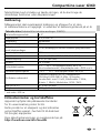
4
Hand receiver mode
Optional: Working with the laser receiver GRX
Use an GRX laser receiver (optional) to carry
out levelling at great distances or when the
laser lines are no longer visible. To work with
a laser receiver, switch the line laser to hand-
held receiver mode by keeping button 7
(handheld receiver mode on / off) pressed.
The laser lines will now pulsate with high
frequency, making the laser lines darker.
The laser receiver can detect these pulsating
laser lines.
Observe the laser receiver‘s operating instructions for line lasers.
!
Due to the special optics required to generate a continuous 360° laser
line, the underlying technology may cause differences in brightness in
different areas of the line. This may lead to different ranges in hand
receiver mode.
!
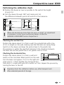
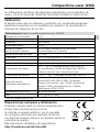
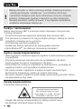
A1
A2
2.
1.
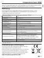
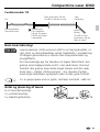
Preparing the calibration check
It is possible for you to check the calibration of the laser. To do this, position
the device midway between 2 walls, which must be at least 5 m apart.
Switch the device on (Laser cross ON). The best calibration results are
achieved if the device is mounted on a tripod.
1. Mark point A1 on the wall.
2. Turn the device through 180° and mark point A2.
You now have a horizontal reference between points A1 and A2.
EN

CompactLine-Laser G360
19
Checking the horizontal line
Position the device about 5 m from a wall and
switch on the cross laser. Mark point B on the wall.
Turn the laser cross approx. 2.5 m to the right and
mark point C. Check whether the horizontal line
from point C is level with point B to within ± 2 mm. Repeat the process by
turning the laser to the left.
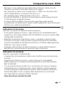
A3
A2
A2
A1
4.
3.
A3
A2
<
0,4 mm / m = OK
Performing the calibration check
When A2 and A3 are more than 0.4 mm / m apart, an adjustment
is necessary. Contact your authorised dealer or else the
UMAREX-LASERLINER Service Department.
!
3. Position the device as near as possible to the wall at the height
of point A1.
4. Turn the device through 180° and mark point A3.
The difference between points A2 and A3 is the tolerance.
B
C
2,5 m
< 2 mm = OK
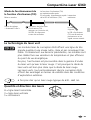
Checking the vertical line
Position the device about 5 m from a wall. Fix a plumb bob with a line
of 2.5 m length on the wall, making sure that the bob can swing freely.
Switch on the device and align the vertical laser to the plumb line.
The precision is within the specified tolerance if the deviation between
the laser line and the plumb line is not greater than ± 2 mm.
Regularly check the calibration before use, after transport and
after extended periods of storage.
!
EN

20
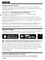
Data transfer
The device features a Bluetooth
®
* function that enables wireless data
transfer to mobile devices with a Bluetooth
®
* interface (such as a smartphone
or tablet).
The system prerequisites for a Bluetooth
®
* connection are specied at
http://laserliner.com/info?an=ble
The device can set up a Bluetooth
®
* connection with Bluetooth 4.0
compatible devices.
The range is set to a maximum distance of 10 m from the terminal device
and greatly depends on the ambient conditions such as the thickness and
composition of walls, sources of interference as well as the transmit / receive
properties of the terminal device.
Once it has been activated, Bluetooth
®
* remains switched on indenitely as
the radio system is designed with exceptionally low power consumption.
A mobile device can link up to the active measuring device via an app.
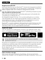
Application (app)
An app is required to use the Bluetooth
®
* function. You can download the
app from the corresponding stores for the specific type of terminal device:
After starting the app and activating the Bluetooth
®
* function, a connection
can be set up between a mobile device and the measuring device. If the app
detects several active measuring devices, select the matching device.
This measuring device can be connected automatically the next time it
is switched on.
* The Bluetooth
®
word mark and the logo are registered trademarks of Bluetooth SIG Inc.
Make sure that the Bluetooth
®
* interface of the mobile device
is activated.
!
Additional functions via the app
The app offers a range of additional functions. If it is not possible to control
your device via the app for technical reasons, reset the device to the factory
EN

CompactLine-Laser G360
21
Calibration
The meter needs to be calibrated and tested on a regular basis to ensureit
produces accurate measurement results. We recommend carrying out
calibration once a year.
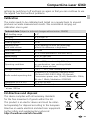
Technical data (Subject to technical changes without notice. 20W02)
Self-levelling range
± 3°
Accuracy
± 0,4 mm / m
Levelling automatic
Visibility (typical)* 30 m
Working range
with hand receiver
30 m (depends on how the technology
affects the difference in brightness)
Laser wavelength 515 nm
Laser class
2 / < 1 mW (EN 60825-1:2014/AC:2017)
Power supply
4 x 1,5V LR6 (AA)
Operating time
approx. 6 hours
Operating conditions
0°C … 50°C, max. humidity 80% rH,
no condensation, max. working altitude
4000 m above sea level
Storage conditions
-10°C … 70°C, max. humidity 80% rH
Radio module operating data
Bluetooth LE 4.x interface; Frequency band:
ISM band 2400–2483.5 MHz, 40 channels;
Transmission power: max. 10 mW; Bandwidth: 2 MHz;
Bit rate: 1 Mbit/s; Modulation: GFSK/FHSS
Dimensions (W x H x D)
87 x 96 x 56 mm
Weight
350 g (incl. batteries)
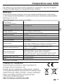
EU directives and disposal
This device complies with all necessary standards
for the free movement of goods within the EU.
This product is an electric device and must be collec-
ted separately for disposal according to the European
Directive on waste electrical and electronic equipment.
Further safety and supplementary notices at:
http://laserliner.com/info?an=AIU
settings by switching it off and back on again so that you can continue to use
the regular functions without problems.
EN
* at max. 300 lux
Page is loading ...
Page is loading ...
Page is loading ...
Page is loading ...
Page is loading ...
Page is loading ...
Page is loading ...
Page is loading ...
Page is loading ...
Page is loading ...
Page is loading ...
Page is loading ...
Page is loading ...
Page is loading ...
Page is loading ...
Page is loading ...
Page is loading ...
Page is loading ...
Page is loading ...
Page is loading ...
Page is loading ...
Page is loading ...
Page is loading ...
Page is loading ...
Page is loading ...
Page is loading ...
Page is loading ...
Page is loading ...
Page is loading ...
Page is loading ...
Page is loading ...
Page is loading ...
Page is loading ...
Page is loading ...
Page is loading ...
Page is loading ...
Page is loading ...
Page is loading ...
Page is loading ...
Page is loading ...
Page is loading ...
Page is loading ...
Page is loading ...
Page is loading ...
Page is loading ...
Page is loading ...
Page is loading ...
Page is loading ...
Page is loading ...
Page is loading ...
Page is loading ...
Page is loading ...
Page is loading ...
Page is loading ...
Page is loading ...
Page is loading ...
Page is loading ...
Page is loading ...
Page is loading ...
Page is loading ...
Page is loading ...

CompactLine-Laser G360
83

CompactLine-Laser G360
Rev20W02
SERVICE
Umarex GmbH & Co. KG
– Laserliner –
Möhnestraße 149, 59755 Arnsberg, Germany
Tel.: +49 2932 638-300, Fax: +49 2932 638-333
info@laserliner.com
Umarex GmbH & Co. KG
Donnerfeld 2
59757 Arnsberg, Germany
Tel.: +49 2932 638-300, Fax: -333
www.laserliner.com
-
 1
1
-
 2
2
-
 3
3
-
 4
4
-
 5
5
-
 6
6
-
 7
7
-
 8
8
-
 9
9
-
 10
10
-
 11
11
-
 12
12
-
 13
13
-
 14
14
-
 15
15
-
 16
16
-
 17
17
-
 18
18
-
 19
19
-
 20
20
-
 21
21
-
 22
22
-
 23
23
-
 24
24
-
 25
25
-
 26
26
-
 27
27
-
 28
28
-
 29
29
-
 30
30
-
 31
31
-
 32
32
-
 33
33
-
 34
34
-
 35
35
-
 36
36
-
 37
37
-
 38
38
-
 39
39
-
 40
40
-
 41
41
-
 42
42
-
 43
43
-
 44
44
-
 45
45
-
 46
46
-
 47
47
-
 48
48
-
 49
49
-
 50
50
-
 51
51
-
 52
52
-
 53
53
-
 54
54
-
 55
55
-
 56
56
-
 57
57
-
 58
58
-
 59
59
-
 60
60
-
 61
61
-
 62
62
-
 63
63
-
 64
64
-
 65
65
-
 66
66
-
 67
67
-
 68
68
-
 69
69
-
 70
70
-
 71
71
-
 72
72
-
 73
73
-
 74
74
-
 75
75
-
 76
76
-
 77
77
-
 78
78
-
 79
79
-
 80
80
-
 81
81
-
 82
82
-
 83
83
-
 84
84


Laserliner CompactLine-Laser G360 Set Owner's manual
- Category
- Laser levels
- Type
- Owner's manual
Ask a question and I''ll find the answer in the document
Finding information in a document is now easier with AI
in other languages
- italiano: Laserliner CompactLine-Laser G360 Set Manuale del proprietario
- français: Laserliner CompactLine-Laser G360 Set Le manuel du propriétaire
- español: Laserliner CompactLine-Laser G360 Set El manual del propietario
- Deutsch: Laserliner CompactLine-Laser G360 Set Bedienungsanleitung
- Nederlands: Laserliner CompactLine-Laser G360 Set de handleiding
- dansk: Laserliner CompactLine-Laser G360 Set Brugervejledning
- polski: Laserliner CompactLine-Laser G360 Set Instrukcja obsługi
Related papers
-
Laserliner MasterCross-Laser 2 Owner's manual
-
Laserliner G360 CompactLine-Laser Operating instructions
-
Laserliner CompactCross-Laser Owner's manual
-
Laserliner SmartLine-Laser G360 Owner's manual
-
Laserliner CompactCube-Laser 3 Owner's manual
-
-
-
-
-
Laserliner SmartCross-Laser Owner's manual
Other documents
-
Leica DISTO User guide
-
Hilti PM 2-L Operating instructions
-
Futech MEGACROSS Owner's manual
-
-
DeWalt DW0822 User guide
-
Parkside PKLL 7 E4 User manual
-
-
Metabo PL 5-30 Owner's manual
-
Hilti PR 2-HS-A12 Operating instructions
-
DeWalt DW088K User manual