Kohler K-1492-H2-0 User manual
- Category
- Above ground pool accessories
- Type
- User manual

Installation Guide
Drop-In Bath Whirlpool
K-1014, K-1110, K-1158,
K-1170, K-1368, K-1369,
K-1375, K-1418, K-1433,
K-1457, K-1460, K-1461,
K-1477, K-1487, K-1492,
K-1496
M product numbers are for Mexico (i.e. K-12345M)
Los números de productos seguidos de M corresponden a México
(Ej. K-12345M)
Français, page “Français-1”
Español, página “Español-1”
1019749-2-H

Important Information
WARNING: When using electrical products, basic precautions should always be followed,
including the following:
DANGER: Risk of electric shock. Connect only to circuits protected by a Ground-Fault
Circuit-Interrupter (GFCI) or Earth-Leakage Circuit-Breaker (ELCB).
Building materials and wiring should be routed away from the pump body and other heat-producing
components of the unit.
Install to permit access for servicing.
A pressure wire connector marked ″Earth/Ground″ is provided within the wiring compartment. To reduce
the risk of electric shock, connect this connector to the grounding terminal of your electric service or supply
panel with copper wire equivalent in size to the circuit conductor supplying this equipment.
Pressure wire connectors are provided on the exterior of the junction box or control within this unit to permit
connection of a bonding conductor between this unit and all other exposed metal in the vicinity, as needed to
comply with local requirements.
Grounding is required. The unit should be installed by a qualified service representative, and grounded.
WARNING: Risk of electric shock. A licensed electrician should make all electrical connections.
WARNING: Risk of electric shock. Disconnect power before servicing.
WARNING: Risk of injury or property damage. Please read all instructions thoroughly before
beginning installation, including the following requirements.
NOTICE: Follow all local plumbing and electrical codes.
Product Information
Electrical Requirements
The installation must have a Class A Ground-Fault Circuit-Interrupter (GFCI) or Earth-Leakage
Circuit-Breaker (ELCB). The GFCI or ELCB protect against line-to-ground shock hazard. Use a 208 - 240 V, 20
A, 50/60 Hz dedicated service for the whirlpool.
Product Notices
WARNING: Unauthorized modification may cause unsafe operation and poor performance of the
whirlpool. Do not relocate the whirlpool pump, or make other modifications to the whirlpool
system, as this could adversely affect the performance and safe operation of the whirlpool. Kohler
Co. shall not be liable under its warranty or otherwise for personal injury or damage caused by any
such unauthorized modification.
Features
″-N1″ Series: Components include a pump, heater, control, shut-off valve, neckjets, pulse cannister, and
illuminated switch (user keypad).
″-H2″ Series: Components include a pump, heater, control and illuminated switch (user keypad).
The whirlpool pump and piping are factory-assembled.
Connections and Service Access
Before installation, ensure proper access to the final connections.
1019749-2-H 2 Kohler Co.

Product Information (cont.)
NOTICE: Provide generous, unrestricted service access to the pump. You must provide access for
servicing the pump and controls. The access must be located immediately next to the pump. Study the
roughing-in information packed with the whirlpool.
Table of Contents
Important Information .............................................................. 2
Product Information ............................................................... 2
Electrical Requirements .......................................................... 2
Product Notices ................................................................ 2
Features ..................................................................... 2
Connections and Service Access ................................................... 2
Tools and Materials ............................................................... 3
Before You Begin ................................................................. 4
Prepare the Site ................................................................. 5
Prepare the Site ................................................................. 6
Prepare the Whirlpool ............................................................. 6
Secure the Whirlpool to the Subfloor .................................................. 7
Cut the Pump Banding Straps ....................................................... 8
Install the Plumbing ............................................................... 8
Install the Optional Pillow - For Models Without Neckjets .................................... 8
Make Electrical Connections ......................................................... 9
Install the Whirlpool Trim Kit ........................................................ 10
Install the Neckjet Pillow (″-N1″ Series Only) ............................................ 10
Test Run the Whirlpool ............................................................ 10
Install the Optional Apron .......................................................... 12
Complete the Finished Wall/Deck .................................................... 12
Complete the Concrete Installation ................................................... 12
Clean-Up After Installation ......................................................... 12
Confirm Proper Operation .......................................................... 13
Operating Sequence ............................................................. 13
Troubleshooting Procedures ........................................................ 14
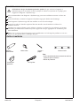
Tools and Materials
• Conventional woodworking or concrete
installation tools and materials
• Drop cloth
Plus:
Silicone Sealant Measuring Tape Pencil Level
Safety Glasses Pipe Wrench
Kohler Co. 3 1019749-2-H

Before You Begin
CAUTION: Risk of product damage. Do not lift the whirlpool by the piping or pump, or use the
piping or pump for structural support of the whirlpool.
We recommend this whirlpool for drop-in or alcove installation.
Inspect the whirlpool for damage before you begin installation.
You must install this whirlpool to an adequately supported, level subfloor.
When used, the optional apron must be installed before the finished floor and wall materials are
completed.
Confirm adequate support for a rim-mounted faucet; large faucets that may be inadvertently used
as a means of support are not appropriate or safe for this installation.
Kohler Co. reserves the right to make revisions in the design of products without notice, as specified
in the Price Book.
1019749-2-H 4 Kohler Co.

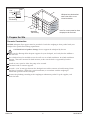
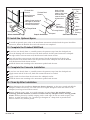
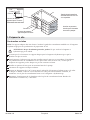
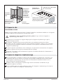
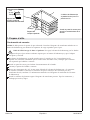
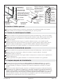
1. Prepare the Site
Concrete Construction
NOTICE: Adequate floor support must be provided. Consult the roughing-in sheet packed with your
whirlpool for specific floor loading requirements.
CAUTION: Risk of product damage. Do not support the whirlpool by the rim.
Make sure the flooring offers adequate support for your whirlpool, and verify that the subfloor is
flat and level.
This whirlpool may be installed next to the wall or in an island installation. An island installation
requires a four side surround. In both instances, make sure the deck is supported by brick or
concrete.
Install an access panel to allow the pump to be serviced.
Construct brick or concrete supports.
Provide a 1/16″ (2 mm) gap between the whirlpool rim and the concrete or brick framing. Frame
the floor, or construct a frame for a raised installation, in accordance with the roughing-in
information packed with the whirlpool.
Position the plumbing according to the roughing-in information packed. Cap the supplies, and
check for leaks.
Brick
Bath
1/16"
(2 mm)
Tile
Approved
Tile Backing
Typical
access
panel
Tile
Approved
Tile Backing
Brick
Whirlpool may be installed
next to the wall or as an
island installation.
Install an access panel to allow
the pump to be serviced.
Kohler Co. 5 1019749-2-H

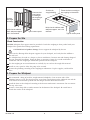
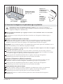
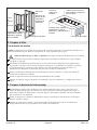
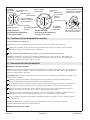
2. Prepare the Site
Wood Construction
NOTICE: Adequate floor support must be provided. Consult the roughing-in sheet packed with your
whirlpool for specific floor loading requirements.
CAUTION: Risk of product damage. Do not support the whirlpool by the rim.
Make sure the flooring offers adequate support for your whirlpool, and verify that the subfloor is
flat and level.
The whirlpool may be used in a drop-in or alcove installation. Construct 2x4 stud framing designed
for your particular installation. Frame the floor, or construct a frame for a raised installation in
accordance with the roughing-in information packed with the whirlpool.
Use the roughing-in cut-out information to carefully lay out and cut the rough deck material.
Install an access panel to allow the pump to be serviced.
Position the plumbing according to the roughing-in information. Cap the supplies, and check for
leaks.
3. Prepare the Whirlpool
We recommend a tiling-in bead for straight-rimmed whirlpools, if one or more sides of the
whirlpool contact a wall. This bead prevents water from seeping between the whirlpool rim and the
wall. Follow the instructions packed with the tiling-in bead to install the bead now.
Install the drain to the whirlpool according to the drain manufacturer’s instructions. Do not connect
the trap at this time.
Position a clean drop cloth or similar material in the bottom of the whirlpool. Be careful not to
scratch the surface of the whirlpool.
Construct 2x4
stud framing
according to
the roughing-in
information.
Position
the rough
plumbing.
Verify that the subfloor
offers adequate support,
and is flat and level.
Typical access panel
Frame the floor according to
the roughing-in information.
Position the
rough plumbing.
Verify that the subfloor offers
adequate support, and is flat
and level.
Typical access panel
1019749-2-H 6 Kohler Co.

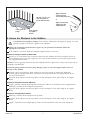
4. Secure the Whirlpool to the Subfloor
CAUTION: Risk of product damage. Do not lift the whirlpool by the piping or pump, or use the
piping or pump for structural support of the whirlpool.
Choose the installation option that best applies to your particular installation. Follow the
appropriate instructions.
If the subfloor is not level, shim the whirlpool support blocks as necessary.
Option for Using a Cement or Mortar Bed
Spread a 2″ (5.1 cm) thick layer of cement or mortar on the subfloor where the whirlpool will be set.
This will help secure, level, and support the unit. Clear all the material away from the pump control
and support block locations.
NOTE: Do not use gypsum cement or drywall compound for this application, as they will not provide an
acceptable, durable bond.
NOTE: The pump control (when the pump banding straps are cut) and support blocks must rest
directly on the subfloor.
Position a piece of plastic drop cloth material on top of the cement or mortar bed. With help,
carefully lift the whirlpool into place, and make sure the pump control and support blocks do not
rest in the bed material.
Insert the drain tailpiece into the trap. Make sure the whirlpool is level and resting on all support
blocks.
Option for Using Construction Adhesive
Apply a generous amount of high-quality construction adhesive to the bottom of the support blocks.
With help, carefully lift the whirlpool into position.
Insert the drain tailpiece into the trap. Make sure the whirlpool is level and resting on all support
blocks.
Option for Using Silicone Sealant
With help, carefully lift the whirlpool into position.
Insert the drain tailpiece into the trap. Make sure the whirlpool is level and resting on all support
blocks.
Apply a continuous bead of high-quality silicone sealant around the entire rim of the whirlpool.
Clear spaces
for support
blocks.
Apply a bead of
silicone sealant
around the entire rim
or
Apply construction
adhesive to the
support blocks.
Spread a 2" (5.1 cm)
layer of cement or
mortar bed material.
Clear space for
pump.
Kohler Co. 7 1019749-2-H

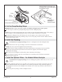
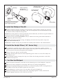
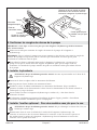
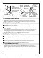
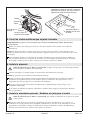
5. Cut the Pump Banding Straps
IMPORTANT! This step is necessary to make your Kohler whirlpool operate more quietly.
Use tin snips to cut the two pump banding straps from the whirlpool pump.
NOTE: Do not raise the pump higher than it was before you cut the pump banding straps. If the pump is
raised too high, it will not prime properly. Make sure the rubber isolation feet are in place.
To minimize whirlpool noise and vibration, be sure the pump is not in direct contact with the
shipping bracket after the pump banding straps are cut. The pump control contains rubber isolation
feet to reduce pump noise.
6. Install the Plumbing
CAUTION: Risk of property damage. Ensure a watertight seal on the whirlpool drain.
Connect the drain to the trap according to the drain manufacturer’s instructions.
NOTICE: An access panel will simplify future maintenance.
Install the faucet valving according to the faucet manufacturer’s instructions. Do not install the
faucet trim until instructed. Open the hot and cold water supplies, and check the supply
connections for leakage.
Run water into the whirlpool, and check the drain connections for leakage.
If your whirlpool requires grip rails, install them now according to the installation instructions
packed with the grip rails.
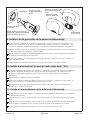
7. Install the Optional Pillow - For Models Without Neckjets
CAUTION: Risk of property damage. Do not submerge the pillow underwater, or use as a seat
cushion.
Clean the whirlpool surface of any soap film or oils. Suction cups are located on the back side of the
pillow. Moisten the back side of the pillow at the suction cup locations, and position the pillow in
the appropriate location on the whirlpool. Press firmly at the suction cup locations with the heel of
your hand.
Detach the pillow by lifting it off the whirlpool surface.
Pump
Wiring
Harness
Rubber Isolation Feet
Control
Cut the pump banding straps.
Moisten the back of the pillow and
firmly press the suction cups against
the whirlpool surface.
Optional Pillow-
For Models
Without Neckjets
1019749-2-H 8 Kohler Co.

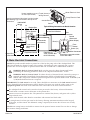
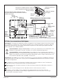
8. Make Electrical Connections
NOTE: The product model number is printed on a label on the pump side of the whirlpool bath. This
label also identifies the electrical rating of the product. All whirlpools come equipped with a wiring
junction box and are designed to operate between 208 VAC and 240 VAC at either 50 Hz or 60 Hz.
WARNING: Risk of electrical shock. Make sure the power has been disconnected before
performing the following procedures. Refer to the “Important Information” section.
WARNING: Risk of electrical shock. To reduce the risk of electrical shock, connect the pump to a
properly grounded Ground-Fault Circuit-Interrupter (GFCI) or Earth-Leakage Circuit-Breaker
(ELCB). This will provide additional protection against line-to-ground shock hazard. A 208-240 V, 20
A, 50/60 Hz dedicated circuit is required.
IMPORTANT! The load neutral is not used. There should be no connection to the load neutral terminal
on the Ground-Fault Circuit-Interrupter (GFCI) breaker. The green wire with the yellow stripe is the
equipment ground and needs to be connected to the neutral bus in the main circuit breaker box.
The whirlpool bath control and system have been pre-wired at the factory. A licensed electrician
should make a routine service connection to the junction box.
Connect service to the junction box. The junction box contains blue, brown, and green with a yellow
stripe colored wires.
Follow local electrical codes. Bond in accordance with national and local codes.
A wiring harness has been pre-wired at the factory, allowing communication between the keypad,
all features, and the control. No additional wiring is required, but ensure that all wires are securely
fastened.
NOTE: Your wiring harness included an antenna for the optional remote control. Do not alter or damage
this antenna during installation.
Heater (models may vary) T-style (shown)
or In-line (not shown)
Heater Electrical Cord
Wiring Harness
Junction Box
Control
Pump Electrical Cord
From
Control
Brown (L2)
* Connections to be Made
at the Circuit Breaker
S/N
* Equipment Ground
Wire Connectors
Neutral Bus
(In Breaker Box)
120/240 VAC
Source
Typical Two-Pole
Circuit Breaker
with GFCI
* Line Neutral
(White Curly
Wire)
Typical Wiring Connection for North America
Ground
(Green with
Yellow Stripes)
*L1
No Connection
(Load Neutral)
Field Wiring
(From Junction Box
to GFCI Breaker)
Electrician to provide suitable
strain relief cable.
Wire
Connector
Blue (L1)
*L2
240 V
120 V
240 V
120 V
Breaker Box
L1 L2N
Bond in accordance with national and local codes.
Open bonding lugs are located at the top of the
junction box.
Kohler Co. 9 1019749-2-H

9. Install the Whirlpool Trim Kit
Install the whirlpool trim kit according to the instructions packed with the trim kit. Pay particular
attention to the jet installation steps below - they are very important and are included here to help
you obtain smooth, trouble-free jet operation.
NOTE: The jet O-ring must be correctly positioned, must be lubricated, and must be in good condition to
permit easy rotation and proper operation of the jet.
Install the O-ring onto the first shoulder of the jet. Lubricate the O-ring with silicone lubricant to
prevent noisy operation of the jet.
Carefully insert the jet into the housing, and lightly push and rotate the jet until it snaps into
position. Do not force the jet.
NOTE: When installed correctly, the jet should turn smoothly both clockwise and counterclockwise.
10. Install the Neckjet Pillow (″-N1″ Series Only)
The whirlpool is supplied with one pillow and two slip covers. The pillow includes a built-in
magnetic reed switch. The neckjets will not operate unless the pillow is installed. Always use a slip
cover to prevent water from spraying from the whirlpool.
Choose a slip cover, and fit it over the pillow.
Carefully slide the pillow down onto the neckjet body grooves until it is secure. The neckjets are
now ready for use.
We recommend periodic cleaning of the slip cover. Follow the cleaning instructions on the label
attached to the slip cover.
11. Test Run the Whirlpool
Check all electrical connections, and make sure the electrical power to the whirlpool is turned on.
Make sure all union connections to the pump and heater are securely hand tightened.
Verify that the pump banding straps have been cut, and that the pump control is resting directly on
the subfloor. Ensure that the rubber isolation feet are in place.
Fill the whirlpool to a level at least 2″ (5.1 cm) above the top of the highest jet.
Operate the whirlpool for 5 minutes (refer to the ″Operating Sequence″ section) and check all
whirlpool piping connections, on the back side, for leaks.
Slide the O-Ring
onto the first
shoulder of the jet.
Inspect and
lubricate the
O-Ring.
Insert the jet into the housing,
and lightly push and rotate
until it snaps in position.
Housing
Slide the pillow onto
the neckjet body.
Fit the slip cover
over the pillow.
Neckjet Body
1019749-2-H 10 Kohler Co.

Test Run the Whirlpool (cont.)
Turn on each of the whirlpool features and verify proper function. Check for any water leakage on
the whirlpool’s back side.
For additional information on whirlpool operation, see ″Confirm Proper Operation″ section.
Kohler Co. 11 1019749-2-H

12. Install the Optional Apron
To install an optional apron, refer to the installation instructions included with the apron. Install this
apron now, before the finished floor and wall materials are completed.
13. Complete the Finished Wall/Deck
If you have not already done so, carefully remove the protective tape from the whirlpool rim.
Cover the framing with water-resistant wall/deck material. Seal the joints between the whirlpool
rim edge and the water-resistant wall/deck material with silicone sealant.
Tape and mud the water-resistant wall/deck material. Install the finished wall/deck to the
water-resistant wall/deck material. Seal the joints between the whirlpool rim and the finished
wall/deck material with silicone sealant.
Install the faucet trim according to the instructions packed with the trim.
14. Complete the Concrete Installation
If you have not already done so, carefully remove the protective tape from the whirlpool rim.
Apply mortar and tile to the wall, deck and surround material as needed.
Apply a bead of sealant where the tile meets the whirlpool surface.
Install the faucet trim according to the instructions packed with the trim.
15. Clean-Up After Installation
When cleaning up after installation, do not use abrasive cleansers, as they may scratch and dull the
whirlpool surface. If necessary, use warm water and a liquid detergent to clean the surface of the
whirlpool, user keypad and remote control.
Remove stubborn stains, paint, or tar with turpentine or paint thinner. Do not allow cleaners
containing petroleum distillates to remain in contact with any whirlpool surfaces for long periods
of time. Remove plaster by carefully scraping with a wood edge. Do not use metal scrapers, wire
brushes, or other metal tools. Use a powder-type detergent on a damp cloth to provide mild
abrasive action to any residual plaster.
Whirlpool
Finished Wall
Material
Water-Resistant
Wall Material
Tiling-in Bead
Framing
Apply silicone sealant to
the edges of the water-
resistant wall material
and the finished wall.
Finished Deck
Material
Whirlpool
Framing Material
Water-
Resistant
Deck Material
Wall Material
Tile
Whirlpool
Brick
Approved
Tile
Backing
Apply silicone
sealant to the
edges of the water-
resistant deck
material and the
finished deck.
Apply
sealant
Alcove Installation Drop-In Installation Concrete Installation
Tile
1019749-2-H 12 Kohler Co.

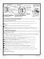
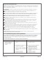
16. Confirm Proper Operation
Fill the Whirlpool
NOTE: Please read these steps carefully before you operate your whirlpool.
Position the jet nozzles so they face down toward the basin. Turn the jet trim rings fully
counterclockwise.
Fill the whirlpool to a water level at least 2″ (5.1 cm) above the top of the highest jet.
NOTE: The water temperature in the whirlpool should not exceed 104°F (40°C). The heater will
automatically turn off as the water temperature approaches 104°F (40°C) and will remain off until the
water cools.
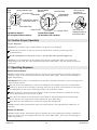
17. Operating Sequence
Models without Neckjets
NOTE: A built-in heater automatically helps to maintain the water temperature when the whirlpool is
running, as long as the water temperature does not exceed 104°F (40°C). The heater will disengage at
higher temperatures.
IMPORTANT! Please refer to your Homeowners Guide for detailed instructions on the user keypad and
optional remote control.
Press the Power On/Off button to turn on the whirlpool. The whirlpool will start at medium flow.
Increase or decrease the water flow by pressing either the up or down arrow buttons on the keypad.
An indicator bar in the center of the keypad shows the water flow volume.
Adjust each jet for optimum air/water mixture. Turn the jet trim clockwise to reduce the air flow,
and counterclockwise to increase the air flow.
Press the heater button to turn the heater off and back on. When illuminated, the indicator light
shows that the water temperature will be maintained up to 104°F (40°C).
Press the Power On/Off button a second time to turn the whirlpool off.
NOTE: A built-in timer automatically stops the pump and motor after approximately 20 minutes of
operation.
Models with Neckjets
NOTE: A built-in heater automatically helps to maintain the water temperature when the whirlpool is
running, as long as the water temperature does not exceed 104°F (40°C). The heater will disengage at
higher temperatures.
Activates Mode
Selected
Power
On/Off
Heater
On/Off
Indicator Bar - Shows
water flow volume
Turn the jet trim
clockwise to
decrease the flow.
Turn the jet trim
counterclockwise to
increase the flow.
Heater Indicator Light
Neckjet Mode -
Adjust Pulse
Heater On/Off
Decreases Flow
Increases Flow
Flow Mode
Increases Flow
Power On/Off
Decreases Flow
Lighted User Keypad
(for whirlpools without neckjets)
Lighted User Keypad
(for whirlpools with neckjets)
Kohler Co. 13 1019749-2-H

Operating Sequence (cont.)
IMPORTANT! Please refer to your Homeowners Guide for detailed instructions on the user keypad and
remote control.
Press Power to turn on the whirlpool. The whirlpool will start at medium flow.
Increase or decrease the water flow by pressing either the up or down arrow buttons on the keypad.
An indicator bar in the center of the keypad shows the water flow volume.
Adjust each jet for optimum air/water mixture. Turn the jet trim clockwise to reduce the air flow,
and counterclockwise to increase the air flow.
Make sure the slip cover is in place on the pillow, and the pillow is attached to the neckjet body.
With the whirlpool operating, rotate the outer ring until the neckjet icon is flashing. Press ″OK″ to
activate the neckjets. The neckjet pulsing action will start at medium speed.
Increase or decrease the neckjet pulsing action by pressing either the up or down arrow buttons on
the keypad.
To activate or deactivate different modes while the neckjets are operating, rotate the outer ring until
the desired mode is flashing and press ″OK″. (Example: To turn the heater off, rotate the dial until
the heater icon is flashing and press ″OK″).
Press ″OK″ while the neckjet mode is flashing to turn off the neckjets.
Press the Power On/Off button a second time to turn the whirlpool off.
NOTE: A built-in timer automatically stops the pump and motor after approximately 20 minutes of
operation.
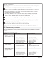
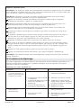
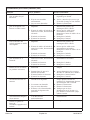
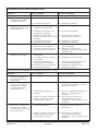
18. Troubleshooting Procedures
This troubleshooting guide is for general aid only. A Kohler Authorized Service Representative or qualified
electrician should correct all electrical problems. For warranty service, contact your dealer or wholesale
distributor.
Troubleshooting the Whirlpool System
Symptoms Probable Causes Recommended Action
1. User keypad does not
illuminate when power
button is pressed or outer
ring is rotated.
A. No power to control. A. Check wiring and connect power.
B. GFCI or ELCB tripped. B. Reset GFCI or ELCB.
C. Wiring harness from user
keypad to control is loose,
disconnected or damaged.
C. Check wiring for proper
connections. Replace wiring
harness if necessary.
D. User keypad does not work. D. Replace user keypad.
E. Control does not work. E. Replace control.
2. Motor starts, but all jets
are not functioning.
A. Jet is closed. A. Rotate jet trim counterclockwise to
open.
B. Jet not installed correctly. B. Reinstall jet; check for O-ring
damage.
C. Jets are blocked. C. Remove blockage.
3. User keypad is
illuminated, but does not
respond to buttons or
outer ring.
A. Control program is locked. A. Reset GFCI or ELCB.
B. Wiring harness from user
keypad to control is loose,
disconnected or damaged.
B. Check wiring for proper
connections. Replace wiring
harness if necessary.
C. User keypad does not work. C. Replace user keypad.
D. Control does not work. D. Replace control.
1019749-2-H 14 Kohler Co.

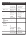
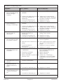
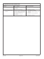
Troubleshooting Procedures (cont.)
Symptoms Probable Causes Recommended Action
4. User keypad indicator bar
keeps scanning at
power-up.
A. Control program is locked. A. Reset GFCI or ELCB.
B. Wiring harness from user
keypad to control is loose,
disconnected or damaged.
B. Check wiring for proper
connections. Replace wiring
harness if necessary.
C. User keypad does not work. C. Replace user keypad.
D. Control does not work. D. Replace control.
5. User keypad is
illuminated, but pump
won’t start.
A. Power cord from pump to
control is loose, disconnected or
damaged.
A. Check wiring for proper
connections.
B. Pump does not work. B. Replace pump.
C. Control does not work. C. Replace control.
6. Motor runs but pump
won’t prime (cavitates).
A. Pump is shimmed too high. A. Lower pump/control to subfloor
level.
B. Small air leak at pump inlet. B. Securely tighten nut(s) on intake
side of pump.
C. Motor/pump does not work. C. Replace motor/pump.
D. Control does not work. D. Replace control.
7. Pump stops before 18
minutes.
A. GFCI or ELCB tripped. A. Identify source of fault, and correct.
Reset GFCI or ELCB.
B. Suction is blocked. B. Remove obstruction.
C. Jets are blocked. C. Remove blockage.
D. Motor overheated and
protection device activated.
D. Check for blockage at suction
and/or jets. Remove blockage and
allow motor to cool.
8. Pump does not
automatically stop after 22
minutes.
A. 20-minute timer inadvertently
disabled.
A. See service manual.
9. Pump won’t turn off
when the power button
on user keypad is
pressed.
A. User keypad does not work. A. Replace user keypad.
B. Control does not work. B. Replace control.
10. Pump operates but
variable speed feature
does not work.
A. Motor/pump does not work. A. Replace motor/pump.
B. Control does not work. B. Replace control.
11. Bath water cools while
pump is operating.
A. Water temperature above 104°F
(40°C).
A. Allow bath water to cool.
B. Heater is turned off on user
keypad.
B. Turn heater on.
C. Wiring from heater to control is
loose, disconnected or damaged.
C. Check wiring for proper
connections.
D. Heater does not work. D. Replace heater.
E. Control does not work. E. Replace control.
12. Noisy operation. A. Pump banding straps have not
been cut.
A. Cut pump banding straps with tin
snips.
B. Dry or dislodged jet O-ring
(squeal).
B. Remove jet, replace and lubricate
O-ring, and reinstall jet.
13. Remote control (if
equipped) does not work.
A. Batteries improperly installed or
dead.
A. Replace batteries.
B. Antenna on wiring harness is
damaged.
B. Replace wiring harness.
Kohler Co. 15 1019749-2-H

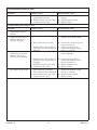
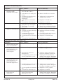
Troubleshooting Procedures (cont.)
Symptoms Probable Causes Recommended Action
C. Remote control not
programmed correctly.
C. See homeowners guide or service
manual.
D. Remote control does not work. D. Replace remote control.
E. Control does not work. E. Replace control.
Troubleshooting the Neckjet System
Symptoms Probable Causes Recommended Action
14. Keypad does not respond
when neckjet mode is
selected.
A. User keypad does not work. A. Replace user keypad.
15. Pump operates but
neckjets do not turn on.
Indicator bar on user
keypad is flashing.
A. Pillow is not installed. A. Make sure the pillow is properly
attached to the neckjet body.
B. Reed switch does not work. B. Check reed switch wiring and
replace if necessary.
C. Wiring harness from neckjet to
control is loose, disconnected or
damaged.
C. Check wiring for proper
connections. Replace wiring
harness if necessary.
16. Pump operates but
neckjets do not turn on.
Indicator bar on user
keypad is NOT flashing.
A. Neckjet line is blocked. A. Disconnect neckjet hoses and
remove blockage.
B. Wiring harness from neckjet to
control is loose, disconnected or
damaged.
B. Check wiring for proper
connections. Replace wiring
harness if necessary.
C. Butterfly valve does not work. C. Replace butterfly valve.
D. Control does not work. D. Replace control.
17. Water flows from neckjets,
but neckjets do not pulse.
A. Wiring harness from neckjet
pulse cannister to control is
loose, disconnected or damaged.
A. Check wiring for proper
connections. Replace wiring
harness if necessary.
B. Pulse cannister does not work. B. Replace pulse cannister.
C. Control does not work. C. Replace control.
1019749-2-H 16 Kohler Co.
Page is loading ...
Page is loading ...
Page is loading ...
Page is loading ...
Page is loading ...
Page is loading ...
Page is loading ...
Page is loading ...
Page is loading ...
Page is loading ...
Page is loading ...
Page is loading ...
Page is loading ...
Page is loading ...
Page is loading ...
Page is loading ...
Page is loading ...
Page is loading ...
Page is loading ...
Page is loading ...
Page is loading ...
Page is loading ...
Page is loading ...
Page is loading ...
Page is loading ...
Page is loading ...
Page is loading ...
Page is loading ...
Page is loading ...
Page is loading ...
Page is loading ...
Page is loading ...
Page is loading ...
Page is loading ...
Page is loading ...
Page is loading ...
Page is loading ...
Page is loading ...
Page is loading ...
Page is loading ...
-
 1
1
-
 2
2
-
 3
3
-
 4
4
-
 5
5
-
 6
6
-
 7
7
-
 8
8
-
 9
9
-
 10
10
-
 11
11
-
 12
12
-
 13
13
-
 14
14
-
 15
15
-
 16
16
-
 17
17
-
 18
18
-
 19
19
-
 20
20
-
 21
21
-
 22
22
-
 23
23
-
 24
24
-
 25
25
-
 26
26
-
 27
27
-
 28
28
-
 29
29
-
 30
30
-
 31
31
-
 32
32
-
 33
33
-
 34
34
-
 35
35
-
 36
36
-
 37
37
-
 38
38
-
 39
39
-
 40
40
-
 41
41
-
 42
42
-
 43
43
-
 44
44
-
 45
45
-
 46
46
-
 47
47
-
 48
48
-
 49
49
-
 50
50
-
 51
51
-
 52
52
-
 53
53
-
 54
54
-
 55
55
-
 56
56


Kohler K-1492-H2-0 User manual
- Category
- Above ground pool accessories
- Type
- User manual
Ask a question and I''ll find the answer in the document
Finding information in a document is now easier with AI
in other languages
- français: Kohler K-1492-H2-0 Manuel utilisateur
- español: Kohler K-1492-H2-0 Manual de usuario
Related papers
-
Kohler K-724-H2-96 Installation guide
-
-
-
-
-
Kohler K-1257-HL-0 Installation guide
-
-
-
Kohler K-716-47 Installation guide
-
Other documents
-
Sterling 66051100-0 Installation guide
-
-
-
 Bathcraft A97242CWWH Installation guide
-
-
-
A&E 151003 User manual
-
-
DMF DID4 User manual
-
 Schon SC70010 Operating instructions

