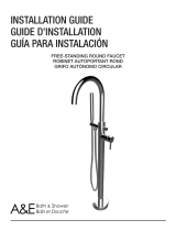
A&E 151003 User manual

Type
User manual

This manual is also suitable for

04MR201494051012
Bathtub freestanding faucet
Robinet autoportant pour baignoire
Owner Manual and Installaon Guide
Manuel du propriétaire et guide d’installaon
This manual is a graphic reference for installaon purposes. Some graphic elements and components may dier.
Ce manuel est une référence graphique pour l’installaon. Certains éléments graphiques et composantes peuvent diérer.
Page 2
Before you begin carefully read all instrucons.
Consult local building codes to ensure that ins-
tallaon complies with standards in your area.
Inspect unit carefully to ensure there is no da-
mages or defects. If you nd a defect, contact
your distributor. If damage has occured during
transport, contact your carrier.
Make sure you have received all the parts requi-
red to install the unit. (tools are not included)
Avant de débuter les travaux, lire aenve-
ment les instrucons de montage.
Consulter le code du bâment de votre région,
an que l'installaon respecte les normes en
vigueur.
Lors de la récepon, inspecter le produit an de
vérier que l’ensemble des pièces est en bonne
condion. Si un problème survient, le signaler
immédiatement au distributeur. Si le dommage
est causé par le transporteur, le contacter im-
médiatement.
S'assurer que toutes les pièces sont incluses.
Powder detergent and liquid abrasive cleaners
may damage surfaces.
Do not allow the surface to come in contact
with abrasive or corrosive products such as ace-
tone, lacquer, thinner, gasoline, etc.
Les détergents en poudre et/ou liquides abrasifs
peuvent endommager les surfaces.
Ne jamais mere en contact la surface avec
des produits corrosifs contenant de l’acétone,
solvant, décapant, essence, etc.
Il est primordial de faire une vidange des canali-
saons d'eau avant de raccorder le robinet.
À défaut de procéder à cee étape, des par-
cules de métal et de soudure présentent dans
les canalisaons d'eau pourraient endommager
la cartouche.
It is essenal to do a ush of the water supply
lines before connecng the faucet.
Disregarding this step can cause damage to
your cartridge. Metal and welding parcles may
ow into the cartridge and damage it.
INFORMATION / INFORMATION
CARE AND MAINTENANCE / SOIN ET ENTRETIEN
IMPORTANT NOTE / NOTE IMPORTANTE
SAFETY INSTRUCTIONS / CONSIGNES DE SÉCURITÉ
Safety goggle
Lunee de sécurité
Gloves
Gants
METRIC
METRIQUE
METRIC
METRIQUE
t
e
f
l
o
n
Page 3
TOOLS AND MATERIAL REQUIRED / OUTILS ET MATÉRIAUX REQUIS
Drill / Perceuse
Drillbits / Forets
Measuring Tape / Ruban à mesurerTeon Tape / Ruban Téon
Lead Pencil / Crayon à mine de plomb
Adjustable Wrench / Clé à molee
Ulity Knife / Couteau à lame rétractable
Allen Key Set / Clés Allen
Wrenches / Clés
Hole Saws / Scies emporte-pièce
Screwdriver / Tournevis
Mutligrip Pliers / Pince mulprise
Basin Wrench / Clé pour lavabo
⅜ x 1½" concret screws
Vis à béton ⅜ x 1½"
ITEM DESCRIPTION
Qté/Qty
1
Faucet body / Corps du robinet
1
2
Flexible hose / Tuyau exible
1
3
Handheld shower / Douchee à main
1
4
Faucet base / Base du robinet
1
A
#12x1¾" Hex. socket head screw (M6x45) / #12x1¾" Vis à tête cylind. à 6 pans creux (M6x45)
4
B
#10x⅜" Round head mechanical screw (M5x10) / #10x⅜" Vis mécanique à tête ronde (M5x10)
4
C
Washer / Rondelle
4
Page 4
PARTS LIST / LISTE DES PIÈCES
A
1 2 3
4
B
C
Page 5
EXPLODED VIEW / VUE EXPLOSÉE
1.5
1.10
1.11
1.12
1.13
1.14
1.15
1.16
1.17
1.18
1.19
1.20
1.21
1.25
1.27
1.28
1.33
1.29
1.31
1.32
1.34
1.26
1.45
1.46
1.47
1.22
1.23
4.1
A
4.7
1.24
C
4.8
4.4
1.25
B
4.9
4.5
1.26
4.2
4.10
4.6
1.4
1.9
1.3
1.8
1.40
1.2
1.7
1.1
1.38
1.37
3.2
3.1
1.6
1.43
1.30
1.35
1.36
1.39
1.41
1.48
1.42
1.49
2.0
1.44
4.3
Page 6
PLUMBING ALIGNMENT
ALIGNEMENT DE LA PLOMBERIE
HOT
CHAUD
COLD
FROID
Face view
Vue de face
Isometric view
Vue isométrique
Water supply lines must be perpendicular with the spout.
Les raccords d'eau se doivent d'être perpendiculaires avec l'orientaon
du bec verseur.
!
Page 7
CONCRETE SUBFLOOR INSTALLATION
INSTALLATION SUR SOUS-PLANCHER DE BÉTON
4"
102mm
Hole dimension
Dimension du trou :
3" min.
76mm min.
Finished oor
Plancher ni
Concrete suboor
Sous-plancher de béton
¾" min.
19mm min.
A
See next page for wood oor installaon.
Voir la page suivante pour une installaon sur plancher de bois.
Concrete suboor installaon: Cont. with secon A at page 9.
Installaon sur sous-plancher de béton: Suite de la secon A à la page 9.
!
Page 8
WOOD FLOOR INSTALLATION
INSTALLATION SUR PLANCHER DE BOIS
2"
51mm
Hole dimension
Dimension du trou :
Suboor
Plancher brut
⅝" min. - 1⅛" max.
16mm min. - 29mm max.
B
Wood oor installaon: Cont. with secon B at page 14.
Installaon sur sous-plancher de béton: Suite de la secon B à la page 14.
!
Page 9
CONCRETE SUBFLOOR INSTALLATION
INSTALLATION SUR SOUS-PLANCHER DE BÉTON
A
Concrete screws not included
Vis à béton non incluses
4.1
A1
A2
Page 10
CONCRETE SUBFLOOR INSTALLATION
INSTALLATION SUR SOUS-PLANCHER DE BÉTON
HOT
CHAUD
COLD
FROID
A
!
Open water supply and maintain pressure for a few minutes to make sure there
is no leak. Close down water supply aerward and proceed to next step.
Ouvrir l'apport d'eau et maintenir la pression pendant quelques minutes an
de vous assurer qu'il n'y a aucune fuite. Refermer l'apport d'eau par la suite et
passer à l'étape suivante.
A3
A4
Page 11
CONCRETE SUBFLOOR INSTALLATION
INSTALLATION SUR SOUS-PLANCHER DE BÉTON
A
B
C
4.1
A5
A6
Page 12
CONCRETE SUBFLOOR INSTALLATION
INSTALLATION SUR SOUS-PLANCHER DE BÉTON
A
A
A7
Page 13
CONCRETE SUBFLOOR INSTALLATION
INSTALLATION SUR SOUS-PLANCHER DE BÉTON
A
T
E
F
L
O
N
A8
A9
Page 14
WOOD FLOOR INSTALLATION
INSTALLATION SUR PLANCHER DE BOIS
B
Vous n'aurez pas besoin de cee pièce
You will not need this part
4.1
4.8
B1
B2
Page 15
WOOD FLOOR INSTALLATION
INSTALLATION SUR PLANCHER DE BOIS
B
B3
B4
Page 16
WOOD FLOOR INSTALLATION /
INSTALLATION SUR PLANCHER DE BOIS
WOOD FLOOR INSTALLATION
INSTALLATION SUR PLANCHER DE BOIS
B
B5
B6
Page 17
WOOD FLOOR INSTALLATION /
INSTALLATION SUR PLANCHER DE BOIS
WOOD FLOOR INSTALLATION
INSTALLATION SUR PLANCHER DE BOIS
B
B7
B8
Page 18
WOOD FLOOR INSTALLATION
INSTALLATION SUR PLANCHER DE BOIS
B
Rubber gasket
Rondelle de caoutchouc
B9
Page 19
WOOD FLOOR INSTALLATION
INSTALLATION SUR PLANCHER DE BOIS
B
View from underneath the oor
Vue sous le plancher
B10
Page 20
WOOD FLOOR INSTALLATION
INSTALLATION SUR PLANCHER DE BOIS
HOT
CHAUD
COLD
FROID
B
View from underneath the oor
Vue sous le plancher
!
Open water supply and maintain pressure for a few minutes to make sure there
is no leak. Close down water supply aerward and proceed to next step.
Ouvrir l'apport d'eau et maintenir la pression pendant quelques minutes an
de vous assurer qu'il n'y a aucune fuite. Refermer l'apport d'eau par la suite et
passer à l'étape suivante.
B11
B12
B13
  • Page 1 1
  • Page 2 2
  • Page 3 3
  • Page 4 4
  • Page 5 5
  • Page 6 6
  • Page 7 7
  • Page 8 8
  • Page 9 9
  • Page 10 10
  • Page 11 11
  • Page 12 12
  • Page 13 13
  • Page 14 14
  • Page 15 15
  • Page 16 16
  • Page 17 17
  • Page 18 18
  • Page 19 19
  • Page 20 20
  • Page 21 21
  • Page 22 22
  • Page 23 23
  • Page 24 24

A&E 151003 User manual

Type
User manual
This manual is also suitable for

Ask a question and I''ll find the answer in the document

Finding information in a document is now easier with AI

in other languages