Page is loading ...
Blu-Fab 3500
and 4500 Series
Processes
OM-221 677C 2006−07
Effective with serial number 222 842
Description
MIG (GMAW) Welding
Flux Cored (FCAW)
Arc Welding Power Source
OWNER’S MANUAL

Thank you and congratulations on choosing Miller. Now you can get the
job done and get it done right. We know you don’t have time to do it any
other way.
That’s why when Niels Miller first started building arc welders in 1929,
he made sure his products offered long-lasting value and superior quality.
Like you, his customers couldn’t afford anything less. Miller products had
to be more than the best they could be. They had to be the best you could
buy.
Today, the people that build and sell Miller products continue the
tradition. They’re just as committed to providing equipment and service
that meets the high standards of quality and value established in 1929.
This Owner’s Manual is designed to help you get the most out of your
Miller products. Please take time to read the Safety precautions. They will
help you protect yourself against potential hazards on the worksite. We’ve
made installation and operation quick and easy. With Miller you can
count on years of reliable service with proper maintenance. And if for
some reason the unit needs repair, there’s a Troubleshooting section that
will help you figure out what the problem is. The parts list will then help
you to decide which exact part you may need to fix the problem.
Warranty and service information for your particular model are also
provided.
Miller Electric manufactures a full line of
welders and welding related equipment. For
information on other quality Miller products, contact your local Miller
distributor to receive the latest full line catalog or individual catalog sheets.
Working as hard as you do
− every power source from
Miller is backed by the most
hassle-free warranty in the
business.
From Miller to You

TABLE OF CONTENTS
SECTION 1 − SAFETY PRECAUTIONS−READ BEFORE USING 1 . . . . . . . . . . . . . . . . . . . . . . . . . . . . . . . . . . .
1-1. Symbol Usage 1 . . . . . . . . . . . . . . . . . . . . . . . . . . . . . . . . . . . . . . . . . . . . . . . . . . . . . . . . . . . . . . . . . . . . . . . .
1-2. Arc Welding Hazards 1 . . . . . . . . . . . . . . . . . . . . . . . . . . . . . . . . . . . . . . . . . . . . . . . . . . . . . . . . . . . . . . . . . .
1-3. Additional Symbols for Installation, Operation, and Maintenance 3 . . . . . . . . . . . . . . . . . . . . . . . . . . . . . .
1-4. EMF Information 3 . . . . . . . . . . . . . . . . . . . . . . . . . . . . . . . . . . . . . . . . . . . . . . . . . . . . . . . . . . . . . . . . . . . . . .
SECTION 2 − DEFINITIONS 4 . . . . . . . . . . . . . . . . . . . . . . . . . . . . . . . . . . . . . . . . . . . . . . . . . . . . . . . . . . . . . . . . . . .
SECTION 3 − INTRODUCTION 6 . . . . . . . . . . . . . . . . . . . . . . . . . . . . . . . . . . . . . . . . . . . . . . . . . . . . . . . . . . . . . . . . .
3-1. Included with Your Unit 6 . . . . . . . . . . . . . . . . . . . . . . . . . . . . . . . . . . . . . . . . . . . . . . . . . . . . . . . . . . . . . . . . .
3-2. Specifications 6 . . . . . . . . . . . . . . . . . . . . . . . . . . . . . . . . . . . . . . . . . . . . . . . . . . . . . . . . . . . . . . . . . . . . . . . .
3-3. Duty Cycle Chart 6 . . . . . . . . . . . . . . . . . . . . . . . . . . . . . . . . . . . . . . . . . . . . . . . . . . . . . . . . . . . . . . . . . . . . .
3-4. Volt-Ampere Curves 6 . . . . . . . . . . . . . . . . . . . . . . . . . . . . . . . . . . . . . . . . . . . . . . . . . . . . . . . . . . . . . . . . . . .
SECTION 4 − INSTALLATION 7 . . . . . . . . . . . . . . . . . . . . . . . . . . . . . . . . . . . . . . . . . . . . . . . . . . . . . . . . . . . . . . . . . .
4-1. Selecting a Location 7 . . . . . . . . . . . . . . . . . . . . . . . . . . . . . . . . . . . . . . . . . . . . . . . . . . . . . . . . . . . . . . . . . . .
4-2. Typical MIG Connections 7 . . . . . . . . . . . . . . . . . . . . . . . . . . . . . . . . . . . . . . . . . . . . . . . . . . . . . . . . . . . . . . .
4-3. Electrical Service Guide 8 . . . . . . . . . . . . . . . . . . . . . . . . . . . . . . . . . . . . . . . . . . . . . . . . . . . . . . . . . . . . . . . .
4-4. Connecting Input Power 8 . . . . . . . . . . . . . . . . . . . . . . . . . . . . . . . . . . . . . . . . . . . . . . . . . . . . . . . . . . . . . . . .
4-5. Remote 14 Receptacle RC1 8 . . . . . . . . . . . . . . . . . . . . . . . . . . . . . . . . . . . . . . . . . . . . . . . . . . . . . . . . . . . .
4-6. Connecting Welding Gun And Weld Cable 9 . . . . . . . . . . . . . . . . . . . . . . . . . . . . . . . . . . . . . . . . . . . . . . . . .
4-7. Installing Wire Guide And Drive Roll 9 . . . . . . . . . . . . . . . . . . . . . . . . . . . . . . . . . . . . . . . . . . . . . . . . . . . . . .
SECTION 5 − OPERATION 10 . . . . . . . . . . . . . . . . . . . . . . . . . . . . . . . . . . . . . . . . . . . . . . . . . . . . . . . . . . . . . . . . . . . .
5-1. Controls 10 . . . . . . . . . . . . . . . . . . . . . . . . . . . . . . . . . . . . . . . . . . . . . . . . . . . . . . . . . . . . . . . . . . . . . . . . . . . . .
5-2. Panel Controls 11 . . . . . . . . . . . . . . . . . . . . . . . . . . . . . . . . . . . . . . . . . . . . . . . . . . . . . . . . . . . . . . . . . . . . . . . .
5-3. Run-In Control and Burnback Control 11 . . . . . . . . . . . . . . . . . . . . . . . . . . . . . . . . . . . . . . . . . . . . . . . . . . . . .
SECTION 6 − MAINTENANCE AND TROUBLESHOOTING 12 . . . . . . . . . . . . . . . . . . . . . . . . . . . . . . . . . . . . . . . .
6-1. Routine Maintenance 12 . . . . . . . . . . . . . . . . . . . . . . . . . . . . . . . . . . . . . . . . . . . . . . . . . . . . . . . . . . . . . . . . . .
6-2. Troubleshooting 12 . . . . . . . . . . . . . . . . . . . . . . . . . . . . . . . . . . . . . . . . . . . . . . . . . . . . . . . . . . . . . . . . . . . . . .
SECTION 7 - ELECTRICAL DIAGRAM 13 . . . . . . . . . . . . . . . . . . . . . . . . . . . . . . . . . . . . . . . . . . . . . . . . . . . . . . . . . .
SECTION 8 - PARTS LIST 14 . . . . . . . . . . . . . . . . . . . . . . . . . . . . . . . . . . . . . . . . . . . . . . . . . . . . . . . . . . . . . . . . . . . . .
WARRANTY

dec_stat_Milan_6/05
Declaration of Conformity for
European Community (CE) Products
This information is provided for units with CE certification (see rating label on unit).
NOTE
Manufacturer: European Contact:
ITW Welding Products Italy S.r.l. Mr. Danilo Fedolfi,
Via Privata Iseo 6/E Managing Director
20098 San Giuliano ITW Welding Products Italy S.r.l.
Milanese, Italy Via Privata Iseo 6/E
Phone: 39(02)98290-1 20098 San Giuliano
Milanese, Italy
Phone: 39(02)98290-1
Fax: 39(02)98290203
European Contact Signature:
Declares that this product: Blu-Fab 3500/4500
conforms to the following Directives and Standards:
Directives
Electromagnetic Compatibility Directives: 89/336/EEC
Low Voltage: 73/23/EEC
Machinery Directives: 98/37/EEC
And their amendments 91/368/EEC, 92/31/EEC, 93/44/EEC, 93/68/EEC
Standards
Electromagnetic compatibility (EMC) Product standard for arc welding equipment: EN50199: August 1995
Safety Requirements for Arc Welding Equipment Part 1: EN 60974-1: 1989
The product technical file is maintained by the responsible Business Unit(s) located at the manufacturing facility.
OM-221 677 Page 1
SECTION 1 − SAFETY PRECAUTIONS - READ BEFORE USING
eng_som_woPPS_3/05
Y Warning: Protect yourself and others from injury — read and follow these precautions.
1-1. Symbol Usage
Means Warning! Watch Out! There are possible hazards
with this procedure! The possible hazards are shown in
the adjoining symbols.
Y Marks a special safety message.
. Means “Note”; not safety related.
This group of symbols means Warning! Watch Out! possible
ELECTRIC SHOCK, MOVING PARTS, and HOT PARTS hazards.
Consult symbols and related instructions below for necessary actions
to avoid the hazards.
1-2. Arc Welding Hazards
Y The symbols shown below are used throughout this manual to
call attention to and identify possible hazards. When you see
the symbol, watch out, and follow the related instructions to
avoid the hazard. The safety information given below is only
a summary of the more complete safety information found in
the Safety Standards listed in Section 1-4. Read and follow all
Safety Standards.
Y Only qualified persons should install, operate, maintain, and
repair this unit.
Y During operation, keep everybody, especially children, away.
ELECTRIC SHOCK can kill.
Touching live electrical parts can cause fatal shocks
or severe burns. The electrode and work circuit is
electrically live whenever the output is on. The input
power circuit and machine internal circuits are also
live when power is on. In semiautomatic or automatic wire welding, the
wire, wire reel, drive roll housing, and all metal parts touching the
welding wire are electrically live. Incorrectly installed or improperly
grounded equipment is a hazard.
D Do not touch live electrical parts.
D Wear dry, hole-free insulating gloves and body protection.
D Insulate yourself from work and ground using dry insulating mats
or covers big enough to prevent any physical contact with the work
or ground.
D Do not use AC output in damp areas, if movement is confined, or if
there is a danger of falling.
D Use AC output ONLY if required for the welding process.
D If AC output is required, use remote output control if present on
unit.
D Additional safety precautions are required when any of the follow-
ing electrically hazardous conditions are present: in damp
locations or while wearing wet clothing; on metal structures such
as floors, gratings, or scaffolds; when in cramped positions such
as sitting, kneeling, or lying; or when there is a high risk of unavoid-
able or accidental contact with the workpiece or ground. For these
conditions, use the following equipment in order presented: 1) a
semiautomatic DC constant voltage (wire) welder, 2) a DC manual
(stick) welder, or 3) an AC welder with reduced open-circuit volt-
age. In most situations, use of a DC, constant voltage wire welder
is recommended. And, do not work alone!
D Disconnect input power or stop engine before installing or
servicing this equipment. Lockout/tagout input power according to
OSHA 29 CFR 1910.147 (see Safety Standards).
D Properly install and ground this equipment according to its
Owner’s Manual and national, state, and local codes.
D Always verify the supply ground − check and be sure that input
power cord ground wire is properly connected to ground terminal in
disconnect box or that cord plug is connected to a properly
grounded receptacle outlet.
D When making input connections, attach proper grounding conduc-
tor first − double-check connections.
D Frequently inspect input power cord for damage or bare wiring −
replace cord immediately if damaged − bare wiring can kill.
D Turn off all equipment when not in use.
D Do not use worn, damaged, undersized, or poorly spliced cables.
D Do not drape cables over your body.
D If earth grounding of the workpiece is required, ground it directly
with a separate cable.
D Do not touch electrode if you are in contact with the work, ground,
or another electrode from a different machine.
D Do not touch electrode holders connected to two welding ma-
chines at the same time since double open-circuit voltage will be
present.
D Use only well-maintained equipment. Repair or replace damaged
parts at once. Maintain unit according to manual.
D Wear a safety harness if working above floor level.
D Keep all panels and covers securely in place.
D Clamp work cable with good metal-to-metal contact to workpiece
or worktable as near the weld as practical.
D Insulate work clamp when not connected to workpiece to prevent
contact with any metal object.
D Do not connect more than one electrode or work cable to any
single weld output terminal.
SIGNIFICANT DC VOLTAGE exists in inverter-type
welding power sources after removal of input
power.
D Turn Off inverter, disconnect input power, and discharge input
capacitors according to instructions in Maintenance Section
before touching any parts.
Welding produces fumes and gases. Breathing
these fumes and gases can be hazardous to your
health.
FUMES AND GASES can be hazardous.
D Keep your head out of the fumes. Do not breathe the fumes.
D If inside, ventilate the area and/or use local forced ventilation at the
arc to remove welding fumes and gases.
D If ventilation is poor, wear an approved air-supplied respirator.
D Read and understand the Material Safety Data Sheets (MSDSs)
and the manufacturer’s instructions for metals, consumables,
coatings, cleaners, and degreasers.
D Work in a confined space only if it is well ventilated, or while
wearing an air-supplied respirator. Always have a trained watch-
person nearby. Welding fumes and gases can displace air and
lower the oxygen level causing injury or death. Be sure the breath-
ing air is safe.
D Do not weld in locations near degreasing, cleaning, or spraying op-
erations. The heat and rays of the arc can react with vapors to form
highly toxic and irritating gases.
D Do not weld on coated metals, such as galvanized, lead, or
cadmium plated steel, unless the coating is removed from the weld
area, the area is well ventilated, and while wearing an air-supplied
respirator. The coatings and any metals containing these elements
can give off toxic fumes if welded.

OM-221 677 Page 2
Arc rays from the welding process produce intense
visible and invisible (ultraviolet and infrared) rays
that can burn eyes and skin. Sparks fly off from the
weld.
ARC RAYS can burn eyes and skin.
D Wear an approved welding helmet fitted with a proper shade of fil-
ter lenses to protect your face and eyes when welding or watching
(see ANSI Z49.1 and Z87.1 listed in Safety Standards).
D Wear approved safety glasses with side shields under your
helmet.
D Use protective screens or barriers to protect others from flash,
glare and sparks; warn others not to watch the arc.
D Wear protective clothing made from durable, flame-resistant mate-
rial (leather, heavy cotton, or wool) and foot protection.
Welding on closed containers, such as tanks,
drums, or pipes, can cause them to blow up. Sparks
can fly off from the welding arc. The flying sparks, hot
workpiece, and hot equipment can cause fires and
burns. Accidental contact of electrode to metal objects can cause
sparks, explosion, overheating, or fire. Check and be sure the area is
safe before doing any welding.
WELDING can cause fire or explosion.
D Remove all flammables within 35 ft (10.7 m) of the welding arc. If
this is not possible, tightly cover them with approved covers.
D Do not weld where flying sparks can strike flammable material.
D Protect yourself and others from flying sparks and hot metal.
D Be alert that welding sparks and hot materials from welding can
easily go through small cracks and openings to adjacent areas.
D Watch for fire, and keep a fire extinguisher nearby.
D Be aware that welding on a ceiling, floor, bulkhead, or partition can
cause fire on the hidden side.
D Do not weld on closed containers such as tanks, drums, or pipes,
unless they are properly prepared according to AWS F4.1 (see
Safety Standards).
D Connect work cable to the work as close to the welding area as
practical to prevent welding current from traveling long, possibly
unknown paths and causing electric shock, sparks, and fire
hazards.
D Do not use welder to thaw frozen pipes.
D Remove stick electrode from holder or cut off welding wire at
contact tip when not in use.
D Wear oil-free protective garments such as leather gloves, heavy
shirt, cuffless trousers, high shoes, and a cap.
D Remove any combustibles, such as a butane lighter or matches,
from your person before doing any welding.
D Follow requirements in OSHA 1910.252 (a) (2) (iv) and NFPA 51B
for hot work and have a fire watcher and extinguisher nearby.
FLYING METAL can injure eyes.
D Welding, chipping, wire brushing, and grinding
cause sparks and flying metal. As welds cool,
they can throw off slag.
D Wear approved safety glasses with side
shields even under your welding helmet.
BUILDUP OF GAS can injure or kill.
D Shut off shielding gas supply when not in use.
D Always ventilate confined spaces or use
approved air-supplied respirator.
HOT PARTS can cause severe burns.
D Do not touch hot parts bare handed.
D Allow cooling period before working on gun or
torch.
D To handle hot parts, use proper tools and/or
wear heavy, insulated welding gloves and
clothing to prevent burns.
MAGNETIC FIELDS can affect pacemakers.
D Pacemaker wearers keep away.
D Wearers should consult their doctor before
going near arc welding, gouging, or spot
welding operations.
NOISE can damage hearing.
Noise from some processes or equipment can
damage hearing.
D Wear approved ear protection if noise level is
high.
Shielding gas cylinders contain gas under high
pressure. If damaged, a cylinder can explode. Since
gas cylinders are normally part of the welding
process, be sure to treat them carefully.
CYLINDERS can explode if damaged.
D Protect compressed gas cylinders from excessive heat, mechani-
cal shocks, physical damage, slag, open flames, sparks, and arcs.
D Install cylinders in an upright position by securing to a stationary
support or cylinder rack to prevent falling or tipping.
D Keep cylinders away from any welding or other electrical circuits.
D Never drape a welding torch over a gas cylinder.
D Never allow a welding electrode to touch any cylinder.
D Never weld on a pressurized cylinder − explosion will result.
D Use only correct shielding gas cylinders, regulators, hoses, and fit-
tings designed for the specific application; maintain them and
associated parts in good condition.
D Turn face away from valve outlet when opening cylinder valve.
D Keep protective cap in place over valve except when cylinder is in
use or connected for use.
D Use the right equipment, correct procedures, and sufficient num-
ber of persons to lift and move cylinders.
D Read and follow instructions on compressed gas cylinders,
associated equipment, and Compressed Gas Association (CGA)
publication P-1 listed in Safety Standards.

OM-221 677 Page 3
1-3. Additional Symbols For Installation, Operation, And Maintenance
FIRE OR EXPLOSION hazard.
D Do not install or place unit on, over, or near
combustible surfaces.
D Do not install unit near flammables.
D Do not overload building wiring − be sure power supply system is
properly sized, rated, and protected to handle this unit.
FALLING UNIT can cause injury.
D Use lifting eye to lift unit only, NOT running
gear, gas cylinders, or any other accessories.
D Use equipment of adequate capacity to lift and
support unit.
D If using lift forks to move unit, be sure forks are
long enough to extend beyond opposite side of
unit.
OVERUSE can cause OVERHEATING
D Allow cooling period; follow rated duty cycle.
D Reduce current or reduce duty cycle before
starting to weld again.
D Do not block or filter airflow to unit.
STATIC (ESD) can damage PC boards.
D Put on grounded wrist strap BEFORE handling
boards or parts.
D Use proper static-proof bags and boxes to
store, move, or ship PC boards.
MOVING PARTS can cause injury.
D Keep away from moving parts.
D Keep away from pinch points such as drive
rolls.
WELDING WIRE can cause injury.
D Do not press gun trigger until instructed to do
so.
D Do not point gun toward any part of the body,
other people, or any metal when threading
welding wire.
MOVING PARTS can cause injury.
D Keep away from moving parts such as fans.
D Keep all doors, panels, covers, and guards
closed and securely in place.
D Have only qualified persons remove doors,
panels, covers, or guards for maintenance as
necessary.
D Reinstall doors, panels, covers, or guards
when maintenance is finished and before re-
connecting input power.
READ INSTRUCTIONS.
D Read Owner’s Manual before using or servic-
ing unit.
D Use only genuine Miller/Hobart replacement
parts.
H.F. RADIATION can cause interference.
D High-frequency (H.F.) can interfere with radio
navigation, safety services, computers, and
communications equipment.
D Have only qualified persons familiar with
electronic equipment perform this installation.
D The user is responsible for having a qualified electrician prompt-
ly correct any interference problem resulting from the installa-
tion.
D If notified by the FCC about interference, stop using the
equipment at once.
D Have the installation regularly checked and maintained.
D Keep high-frequency source doors and panels tightly shut, keep
spark gaps at correct setting, and use grounding and shielding to
minimize the possibility of interference.
ARC WELDING can cause interference.
D Electromagnetic energy can interfere with
sensitive electronic equipment such as
computers and computer-driven equipment
such as robots.
D Be sure all equipment in the welding area is
electromagnetically compatible.
D To reduce possible interference, keep weld cables as short as
possible, close together, and down low, such as on the floor.
D Locate welding operation 100 meters from any sensitive elec-
tronic equipment.
D Be sure this welding machine is installed and grounded
according to this manual.
D If interference still occurs, the user must take extra measures
such as moving the welding machine, using shielded cables,
using line filters, or shielding the work area.
For Gasoline Engines:
Y Engine exhaust contains chemicals known to the State of
California to cause cancer, birth defects, or other reproductive
harm.
For Diesel Engines:
Y Diesel engine exhaust and some of its constituents are known
to the State of California to cause cancer, birth defects, and
other reproductive harm.

OM-221 677 Page 4
1-4. Principal Safety Standards
Safety in Welding, Cutting, and Allied Processes, ANSI Standard Z49.1,
from Global Engineering Documents (phone: 1-877-413-5184, website:
www.global.ihs.com).
Recommended Safe Practices for the Preparation for Welding and Cut-
ting of Containers and Piping, American Welding Society Standard
AWS F4.1 from Global Engineering Documents (phone:
1-877-413-5184, website: www.global.ihs.com).
National Electrical Code, NFPA Standard 70, from National Fire Protec-
tion Association, P.O. Box 9101, 1 Battery March Park, Quincy, MA
02269−9101 (phone: 617−770−3000, website: www.nfpa.org).
Safe Handling of Compressed Gases in Cylinders, CGA Pamphlet P-1,
from Compressed Gas Association, 1735 Jefferson Davis Highway,
Suite 1004, Arlington, VA 22202−4102 (phone: 703−412−0900, web-
site: www.cganet.com).
Code for Safety in Welding and Cutting, CSA Standard W117.2, from
Canadian Standards Association, Standards Sales, 178 Rexdale
Boulevard, Rexdale, Ontario, Canada M9W 1R3 (phone:
800−463−6727 or in Toronto 416−747−4044, website: www.csa−in-
ternational.org).
Practice For Occupational And Educational Eye And Face Protection,
ANSI Standard Z87.1, from American National Standards Institute, 11
West 42nd Street, New York, NY 10036−8002 (phone: 212−642−4900,
website: www.ansi.org).
Standard for Fire Prevention During Welding, Cutting, and Other Hot
Work, NFPA Standard 51B, from National Fire Protection Association,
P.O. Box 9101, 1 Battery March Park, Quincy, MA 02269−9101 (phone:
617−770−3000, website: www.nfpa.org).
OSHA, Occupational Safety and Health Standards for General Indus-
try, Title 29, Code of Federal Regulations (CFR), Part 1910, Subpart Q,
and Part 1926, Subpart J, from U.S. Government Printing Office, Super-
intendent of Documents, P.O. Box 371954, Pittsburgh, PA 15250 (there
are 10 Regional Offices−−phone for Region 5, Chicago, is
312−353−2220, website: www.osha.gov).
1-5. EMF Information
Considerations About Welding And The Effects Of Low Frequency
Electric And Magnetic Fields
Welding current, as it flows through welding cables, will cause electro-
magnetic fields. There has been and still is some concern about such
fields. However, after examining more than 500 studies spanning 17
years of research, a special blue ribbon committee of the National
Research Council concluded that: “The body of evidence, in the
committee’s judgment, has not demonstrated that exposure to power-
frequency electric and magnetic fields is a human-health hazard.”
However, studies are still going forth and evidence continues to be
examined. Until the final conclusions of the research are reached, you
may wish to minimize your exposure to electromagnetic fields when
welding or cutting.
To reduce magnetic fields in the workplace, use the following
procedures:
1. Keep cables close together by twisting or taping them.
2. Arrange cables to one side and away from the operator.
3. Do not coil or drape cables around your body.
4. Keep welding power source and cables as far away from opera-
tor as practical.
5. Connect work clamp to workpiece as close to the weld as possi-
ble.
About Pacemakers:
Pacemaker wearers consult your doctor before welding or going near
welding operations. If cleared by your doctor, then following the above
procedures is recommended.
OM-221 677 Page 5
SECTION 2 − DEFINITIONS
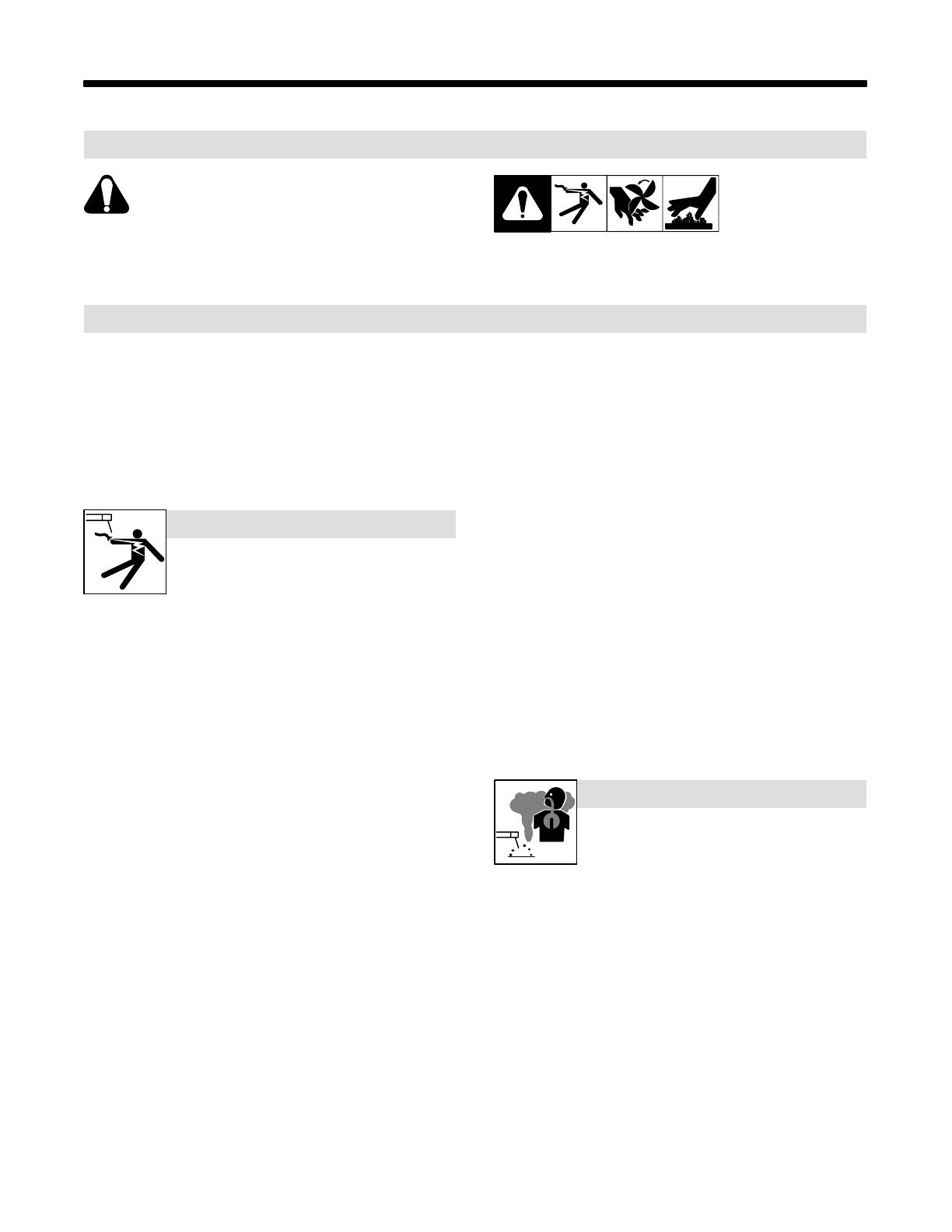
Warning! Watch Out! There are possible
hazards as shown by the symbols.
1 Electric shock can kill.
1.1 Wear dry insulating gloves. Do not
touch electrode with bare hand. Do
not wear wet or damaged gloves.
1.2 Protect yourself from electric shock
by insulating yourself from work and
ground.
1.3 Disconnect input plug or power
before working on machine.
2 Breathing welding fumes can be
hazardous to your health.
2.1 Keep your head out of the fumes.
2.2 Use forced ventilation or local
exhaust to remove the fumes.
2.3 Use ventilating fan to remove fumes.
3 Welding sparks can cause explosion
or fire.
3.1 Keep flammables away from welding.
Do not weld near flammables.
3.2 Welding sparks can cause fires.
Have a fire extinguisher nearby, and
have a watchperson ready to use it.
3.3 Do not weld on drums or any closed
containers.
4 Arc rays can burn eyes and injure
skin.
4.1 Wear hat and safety glasses. Use
ear protection and button shirt collar.
Use welding helmet with correct
shade of filter. Wear complete body
protection.
5 Become trained and read the
instructions before working on the
machine or welding.
6 Do not remove or paint over (cover)
the label.
Do not discard this product with
general waste.
Reuse or recycle Waste Electrical
and Electronic Equipment (WEEE)
by disposing at a designated collec-
tion facility.
Contact your local recycling office
or your local distributor for further
information.
OM-221 677 Page 6
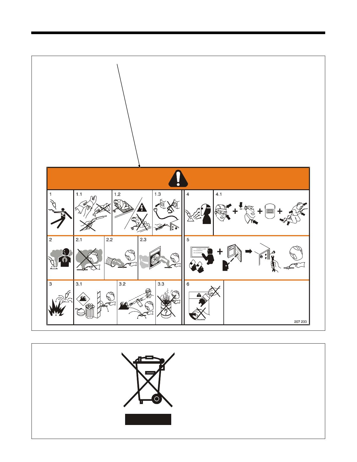
Warning! Watch Out! There are
possible hazards as shown by the
symbols.
Electric shock from wiring can kill.
Disconnect input plug or power
before working on machine.
Read the Owner’s Manual before
working on this machine.
1 Consult rating label for input
power requirements, and
check power available at the
job site − they must match.
2 Read Owner’s Manual and
inside labels for connection
points and procedures.
3 Move jumper links as shown
on inside label to match
voltage at job site.
4 Having a loop of extra length,
connect grounding conductor
first.
5 Connect line input conductors
as shown on inside label −
double-check all connections,
jumper link positions, and
input voltage before applying
power.
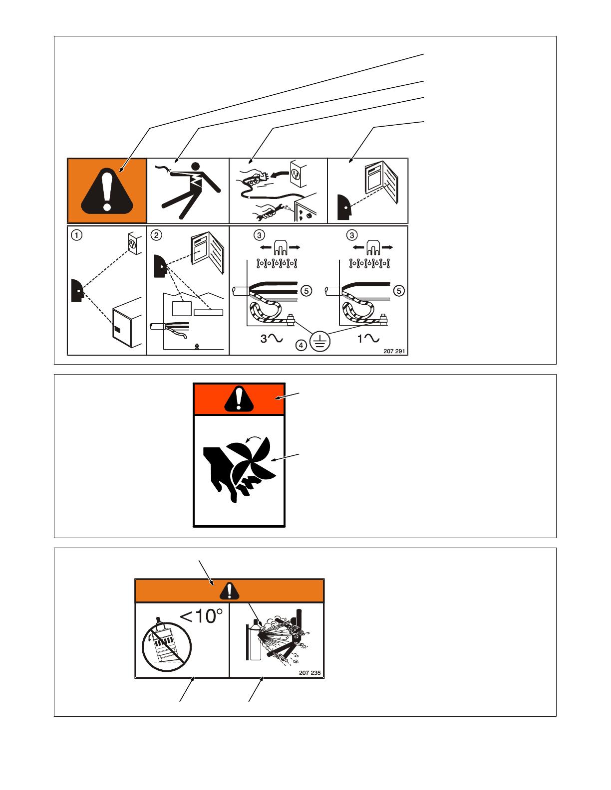
1 Warning! Watch Out! There
are possible hazards as
shown by the symbols.
2 Moving parts, such as fans,
can cut fingers and hands and
cause injury. Keep away from
moving parts.
S-176 106
1
2
1 Warning! Watch Out! There
are possible hazards as
shown by the symbols.
2 Falling unit can cause injury.
Do not move or operate unit
where it could tip.
3 Cylinders can expolde if
damaged. Protect
compressed gas cylinders
from excessive heat,
mechanical shock, slag, open
flames, sparks, and arcs.
1
23
1
OM-221 677 Page 7
SECTION 3 − INTRODUCTION
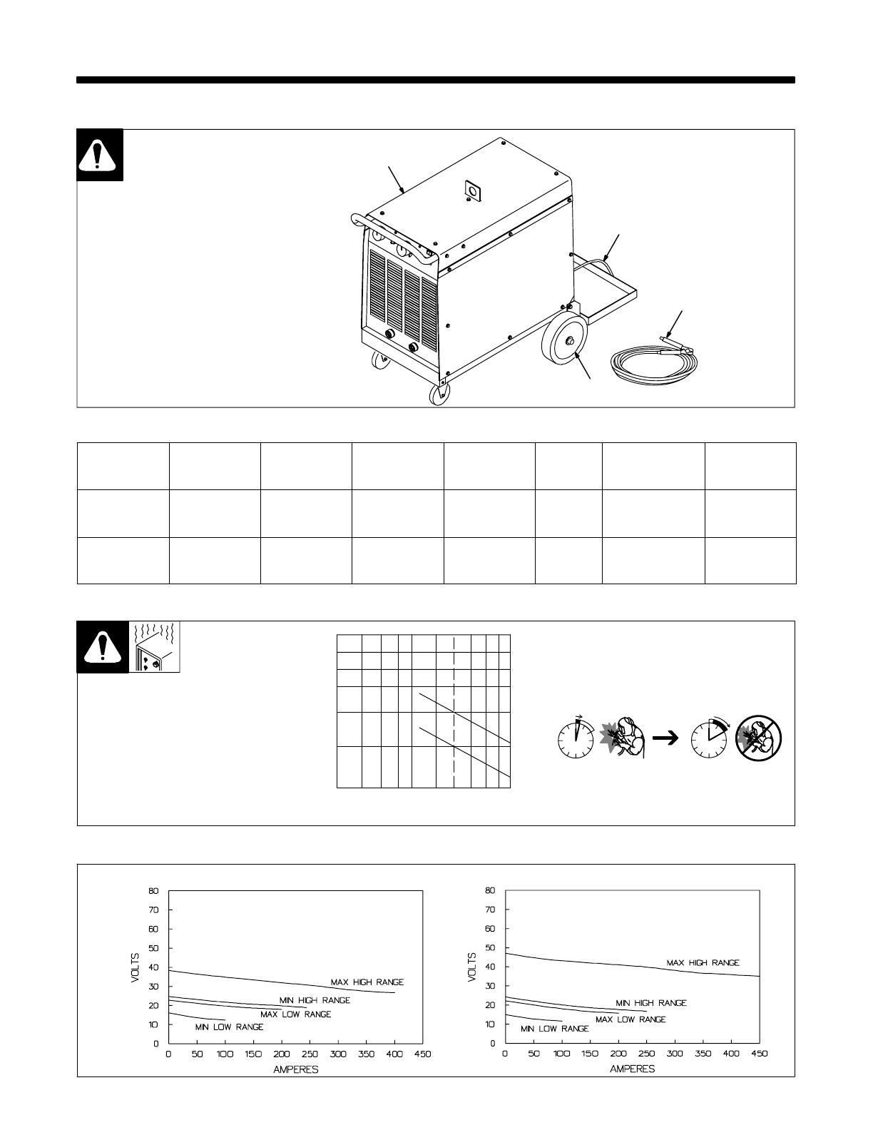
3-1. Included with Your Unit
1 Power Source
2 Power Cord (4m)
3 Work Cable and Clamp (4m)
4 Running Gear
1
2
4
3
3-2. Specifications
Rated Output
at 45% Duty
Cycle
Welding
Range
Max. OVC Input Rating KVA Dimensions Net Weight
Blu-Fab 3500 350 A 32 V 16-32 38 400−18A 11.8 KVA Length: 1040mm
Height: 760mm
Width: 435mm
146 kg
Blu-Fab 4500 450 A 37 V 14-37 47 400-27A 17.7 KVA Length: 1040mm
Height: 760mm
Width: 435mm
156 kg
3-3. Duty Cycle Chart
4.5 Minutes
Welding
5.5 Minutes
Resting
Duty cycle is percentage of 10
minutes that unit can weld at rated
load without overheating.
Y Exceeding duty cycle can
damage unit and void
warranty.
Blu-Fab 3500: 45% Duty Cycle at 32V, 350A
Blu-Fab 4500: 45% Duty Cycle at 37V, 450A
20 25 30 40 50 60 70809010035
800
700
600
500
400
300
200
WELDING AMPERES
% DUTY CYCLE
350
450
3-4. Volt-Ampere Curves
Blu-Fab 3500 Blu-Fab 4500
OM-221 677 Page 8
SECTION 4 − INSTALLATION
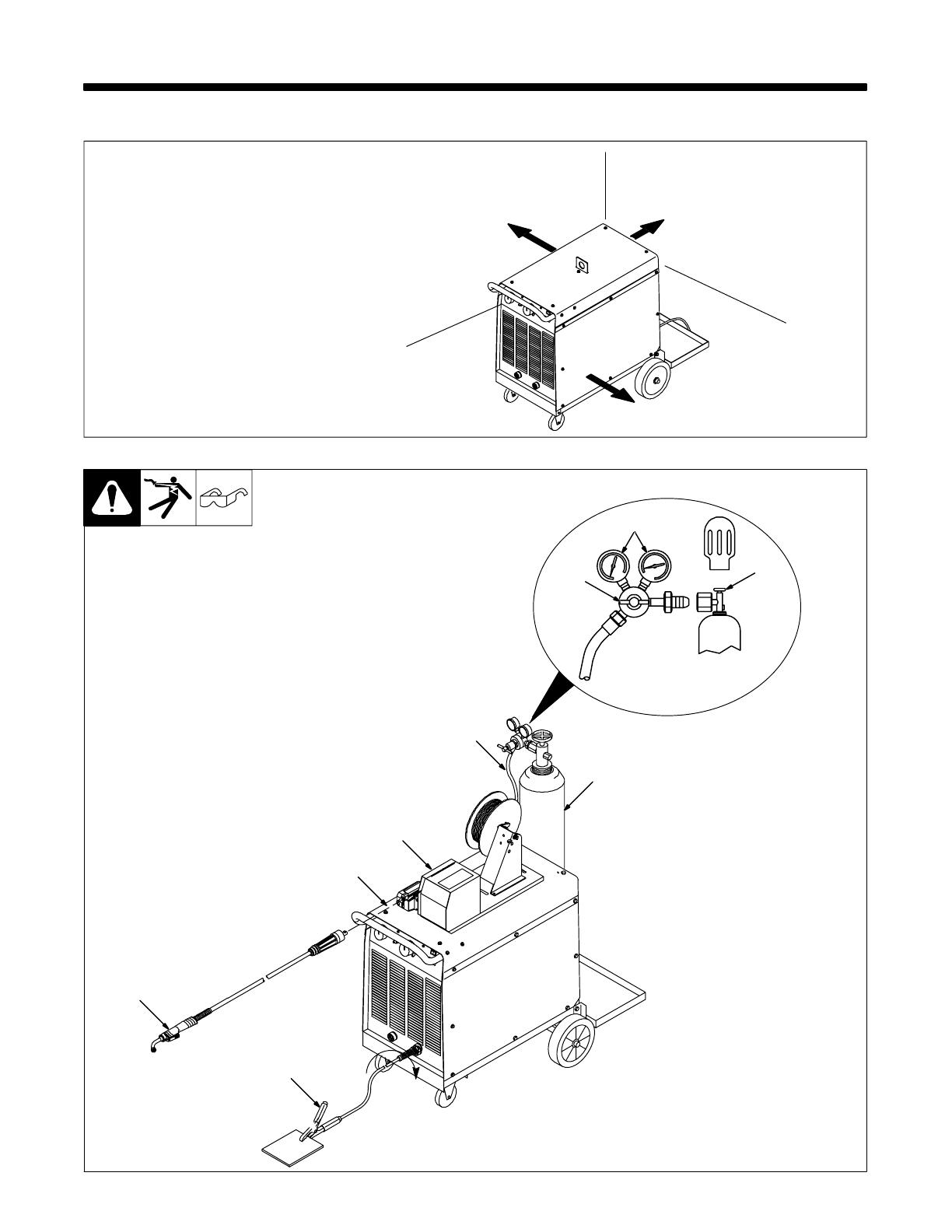
4-1. Selecting a Location
Position unit so air can circulate.
500 mm
500 mm
500 mm
4-2. Typical MIG Connections
1 Power source
2 Work clamp (connect to receptacle as shown)
3 Cylinder (chain to running gear)
4 Cylinder valve
Open valve slightly so gas flow blows dirt from valve.
Close valve.
5 Regulator/Flow gauge
Install so face is vertical.
6 Flow adjust
7 Gas supply line
8 Wire feeder
9 MIG torch
1
4
5
6
3
7
8
2
9

OM-221 677 Page 9
4-3. Electrical Service Guide
Blu-Fab 3500 Blu-Fab 4500
Input Voltage 400 400
Input amperes at rated output 21A 30A
Fuse or circuit breaker rating (max. rec) 21A 30A
Input conductor size 6 mm
2
6 mm
2
Grounding conductor size** 6 mm
2
6 mm
2
** Larger power cord may be required for cable length greater than 3 meters. Consult national or local regulations.
4-4. Connecting Input Power
Tools Needed:
Y Have only qualified persons
make this installation.
Y Special installation may be
required where gasoline or
volatile liquids are present −
consult national or local reg-
ulations.
GND/PE
Connect first.
GND/PE
L1
L2
L3
4-5. Remote 14 Receptacle RC1
Socket Information
24 VOLTS AC
OUTPUT
A 24 volts ac.
2
4
VOLTS AC
OUTPUT
(CONTACTOR)
B Contact closure to A completes 24 volts ac contactor control circuit.
OUTPUT
115 VOLTS AC
I 115 volts AC, protected b
y
fuse.
OUTPUT
115 VOLTS AC
I
115 volts AC
,
protected by fuse
.
GND
K
G
Chassis common.
Circuit common for 24 and 115 volts ac circuits.
OM-221 677 Page 10
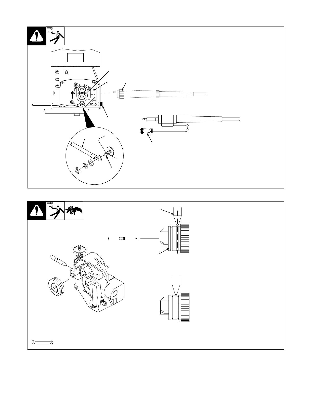
1 Gun Securing Knob
2 Gun Block
3 Gun Outlet Wire Guide
Loosen knob, insert gun into block.
Position outlet wire guide as close
as possible to drive rolls without
touching. Tighten knob.
4 Gun Trigger Plug
5 Gun Trigger Receptacle
6 Weld Cable Terminal
7 Weld Cable From Welding
Power Source
4-6. Connecting Welding Gun And Weld Cable
Euro Torch
1
3
7
6
2
4
5
US Torch
1 Inlet Wire Guide
2 Intermediate Wire Guide
Install and secure inlet wire guide,
and intermediate wire guide.
3 Drive Roll
Install drive rolls and turn drive roll
nut one click.
During maintenance intervals,
remove drive rolls, and clean
grooves using a wire brush. Check
general condition of drive rolls.
Aligning Wire Guide And Drive
Rolls:
View is from top of drive rolls
looking down with pressure assem-
bly open.
Turn screw in or out until drive roll
groove lines up with wire guide.
Close pressure roll assembly.
Repeat for remaining drive rolls un-
til all drive rolls line up with wire
guides as shown.
4-7. Installing Wire Guide And Drive Roll
802 310-A
Tools Needed:
3/8 in
Incorrect Alignment
Correct Alignment
1−2
3
OM-221 677 Page 11
SECTION 5 − OPERATION
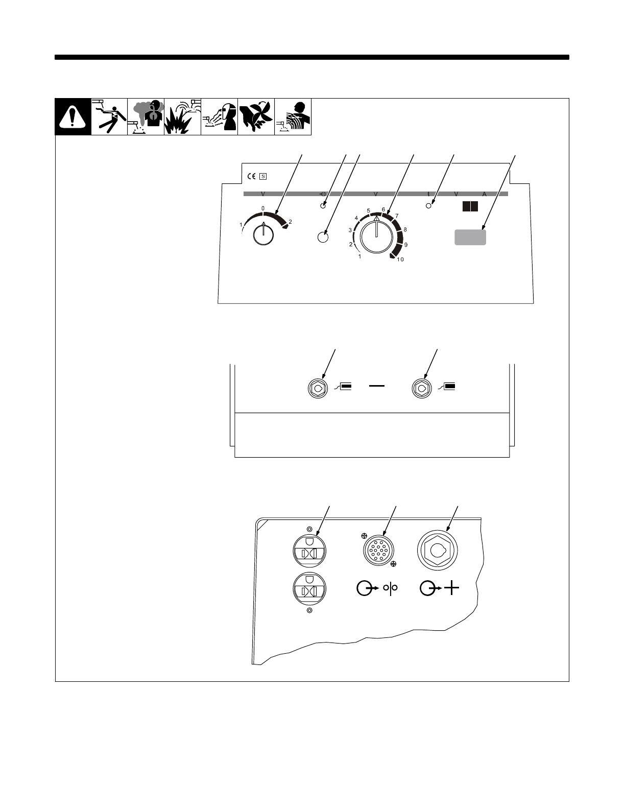
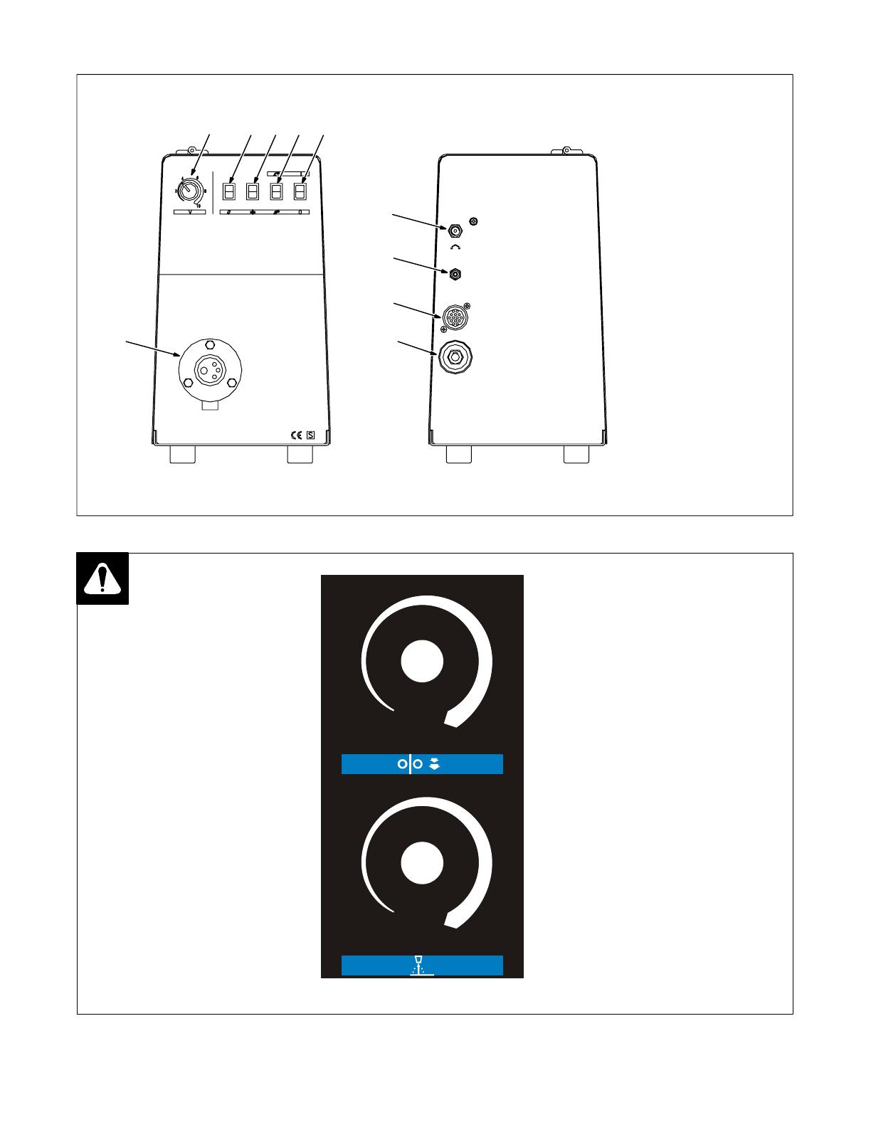
5-1. Controls
1 Power Switch
The power switch is a selector knob
which permits selection of operation
on either of the two available ranges
(I and II) and the center position is off.
2 Indicator Lamp
This lights up when the power switch
is placed in the ON position.
3 Protection Fuse
Fuse F protects the control circuit.
Should it become necesary to re-
place any fuse in the welding power
source, be sure to substitute with one
of the same size and rating.
4 Use this control to adjust weld
voltage 10 position switch. 20
weld setting, 10 high range (I),
10 low range (II).
5 High Temperature Shutdown
Light
This lights up when unit overheats
and shuts down.
6 Voltage/Amperage Meter.
Use toggle switch to select voltage or
amperage.
7 Low Inductance Negative
Output Terminal
Connect work lead here for most
“short-arc” applications.
8 High Inductance Negative
Terminal
Connect work lead here for stainless
steel and spray arc conditions.
9 115 AC Receptacle (optional)
Located on the rear panel is a recep-
tacle which provides power to the gas
heater, when welding with CO
2
shielding gas and for the cooling sys-
tem.
10 Wire Feeder Power Cable
Receptacle
Located on the rear panel is a recep-
tacle used to supply operating power
to the wire feed unit.
11 Positive Out Terminal
115 VAC
Front Panel
Back Panel
4
11109
7 8
6
51 32
OM-221 677 Page 12
5-2. Panel Controls
1 2 3 4 5
7
8
9
10
6
1 Voltage Control
2 Purge Control
3 Jog
42T−4T Switch
5 Power ON-OFF
6 Torch Connection
7 Circuit Breaker
8 Gas In Connector
9 Control Cable Connection
10 Weld Cable Connection
5-3. Run-In Control and Burnback Control
2
4
6
8
10
2
4
6
8
10
t
Run-In Control
Use control to set wire feed speed
before arc initiation
After arc initiation, wire feed speed
is controlled by the wire feed speed
control on the front control panel.
Burnback Control
Control adjusts the time welding
wire is energized after wire feed
stops.
OM-221 677 Page 13
SECTION 6 − MAINTENANCE AND TROUBLESHOOTING
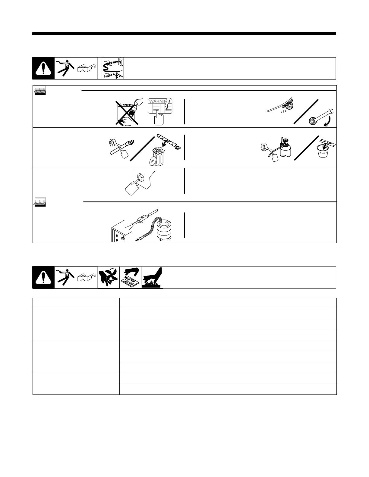
6-1. Routine Maintenance
Y Disconnect power before maintaining.
. Maintain more often during severe conditions.
3 Months
Replace unreadable labels. Clean and tighten weld terminals.
Repair or replace cracked weld
cable.
Repair or replace cracked gas
hose.
Replace o-ring in Electrode/Gas
Output receptacle if cracked.
6 Months
Blow out or vacuum inside.
OR
6-2. Troubleshooting
Trouble Remedy
No weld output; fan does not run.
Place line disconnect switch in On position (see Section 4-4).
Check and replace line fuse(s), if necessary, or reset circuit breaker (see Section 4-4).
Check for proper input power connections (see Section 4-4).
No weld output; fan on.
Check and replace if necessary.
Tighten wire feeder connection to Remote 14 receptacle.
Unit overheated. Allow unit to cool (see Section 3-3).
Fan not operating; weld output
available
Check for and remove anything blocking fan movement.
ava
il
a
bl
e.
Have Factory Authorized Service Agent check fan motor.

OM-221 677 Page 14
Notes

OM-221 677 Page 15
SECTION 7 - ELECTRICAL DIAGRAM
RC1
RC2
RC1
IN RECT.TP
OL
R
PL
22 20 21 115
BG AKI
14
13
20
115V24V
AT
RC3
400V
FM
9
10
230V
S3
11
F
GND
R
S
T
5
3
1
W
W
W
2
S2
RL 1
SL 2
TL 3
6
4
7
19
8
RL 1
SL 2
TL 3
S3
PRI.
B
B
B
212121
12
4
6
3
5
24
12
24 Vac
DIGITAL A-V
26
25
29
+
SHUNT
1234 567 8 9101112
B
B
B
MT
SEC.
SR1
Vc
28 30
31
Z
1
2
3
4
5
6
7
8
9
10
POSIZIONI
X
X
X
X
X
X
X
X
X
X
X
X
X
X
X
X
X
X
X
XX
X
X
X
X
X
X
X
X
X
123456789101112
S2R1 T3
w
23
CR
CR
CR
956142300_9−10−04
RRR
C1 C2 C3
OPTIONAL
OM-221 677 Page 16
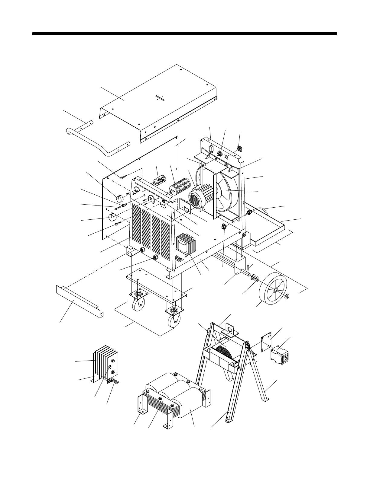
SECTION 8 - PARTS LIST
8-1. Main Assembly
1
2
3
4
5
9
7
6
4
10
35
14
12
13
15
37
16
17
38
18
21
23
24
25
26
10
36
27
28
29
30
31
33
19
20
39
34
40
11
32
22
9/13/04
*
*
*
47
44
46
45
43
42
41
48
/