DirecTV HD65W20 Receiver User manual
- Category
- LCD TVs
- Type
- User manual
This manual is also suitable for

’ :
-
HD65W20


Please do not send any products to the Indianapolis address listed in this manual or on the carton. This will only add delays
in service for your product.
Thomson multimedia Inc.
10330 North Meridian Street
Indianapolis, IN 46290
©2001 Thomson multimedia Inc.
Trademark(s)® Registered
Marca(s) Registrada(s)
Activation of programming may be subject to credit approval and requires valid service address, social security number and/or
major credit card. Programming subject to change. You must be physically located in the U.S. to receive DIRECTV service.
DIRECTV services not available outside the U.S. DIRECTV programming is sold separately and independently of DIRECTV
system hardware. A valid programming subscription is required to operate DIRECTV System hardware. Activate your DIRECTV
programming today at 1-800-DIRECTV (1-800-347-3288). Receipt of DIRECTV programming is subject to the terms of the
DIRECTV Customer Agreement; a copy is provided at DIRECTV.com and with your first bill. DIRECTV and the Cyclone Design
logo are trademarks of DIRECTV, Inc., a unit of Hughes Electronic Corp., and is used with permission.
Printed in the USA
TOCOM 15739330

Important Information
WARNING
To reduce the risk of fire or
shock hazard, do not expose this
product to rain or moisture.
This symbol indicates
"dangerous voltage" inside the
product that presents a risk of
electric shock or personal injury.
This symbol indicates
important instructions
accompanying the product.
Refer to the identification/rating label located on the back panel of your product for its proper
operating voltage.
This device complies with part 15 of the FCC rules. Operation is subject to the condition that
this device does not cause harmful interference. FCC Regulations state that unauthorized
changes or modifications to this equipment may void the user’s authority to operate it. Use of
this device without the supplied power cord may cause this set to be non-compliant with FCC
part 15 regulations.
If fixed (non-moving) images are left on the screen for long periods, they may be
permanently imprinted on the screen. Such images include network logos, phone
numbers, and video games. This damage is not covered by your warranty.
Extended viewing of channels displaying these images should be avoided.
Cable TV Installer: This reminder is provided to call your attention to Article 820-40 of the
National Electrical Code (Section 54 of the Canadian Electrical Code, Part 1) which provides
guidelines for proper grounding and, in particular, specifies that the cable ground shall be
connected to the grounding system of the building as close to the point of cable entry as
practical.
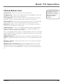
Product Registration
Please fill out the product registration card and return it immediately. Returning the card allows us to contact you if
needed.
Keep your sales receipt to obtain warranty parts and service and for proof of purchase. Attach it here and record the
serial and model numbers in case you need them. The numbers are located on the back of the product.
Model No. _______________________________________________________
Serial No. ________________________________________________________
Purchase Date: ____________________________________________________
Dealer/Address/Phone: _____________________________________________
To reduce the risk of electric shock, do not remove
cover (or back). No user-serviceable parts inside.
Refer servicing to qualified service personnel.
WARNING
RISK OF ELECTRIC
SHOCK. DO NOT OPEN.

This page left intentionally blank

3
Table Of Contents
Setup and Connections ............................................................................ 7
Step 1: Unpack the System .......................................................................................... 8
Step 2: Connect Your TV to Other Components ........................................................ 8
Jacks and Cables ................................................................................................... 9
Front Buttons ......................................................................................................10
Back of the TV .....................................................................................................12
The Basic Connection ......................................................................................... 14
The Advanced Connection .................................................................................15
Connecting Speakers to the TV ......................................................................... 16
Connecting a Stereo Amplifier ..........................................................................17
Step 3: Place Batteries in the Remote Control ......................................................... 18
Step 4: Plug in and Turn on the System .................................................................... 18
Step 5: Complete the Interactive Setup .................................................................... 18
Step 6: Order Programming ...................................................................................... 18
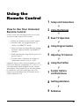
Using the Remote Control ..................................................................... 19
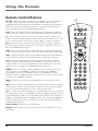
Remote Control Buttons ............................................................................................ 20
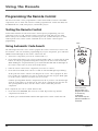
Programming the Remote Control ........................................................................... 22
Using the Remote to Control a Component .....................................................23
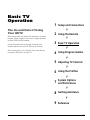
Basic TV Operation ................................................................................. 25
About the Channel Banner ....................................................................................... 26
Changing Between DIRECTV and TV Mode ............................................................. 28
Changing Channels .................................................................................................... 29
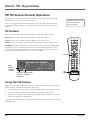
PIP (Picture-in-Picture) Operation ............................................................................. 30
PIP Buttons ..........................................................................................................30
Using the PIP Feature .........................................................................................30
PIP Problems? ...................................................................................................... 31
Using the INPUT Button ............................................................................................ 32
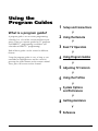
Using the Program Guides ..................................................................... 33
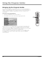
Bringing Up the Program Guides .............................................................................. 34
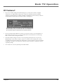
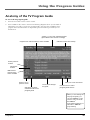
Anatomy of the TV Program Guide .......................................................................... 35
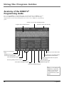
Anatomy of the DIRECTV® Programming Guide .................................................... 36
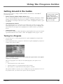
Getting Around in the Guides................................................................................... 37
Tuning to a Program .......................................................................................... 37
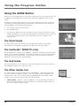
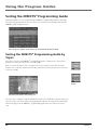
Using the GUIDE Button ............................................................................................ 38
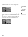
Sorting the DIRECTV® Programming Guide ............................................................ 40
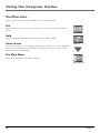
The Other Icons .......................................................................................................... 44

Table Of Contents
4
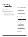
Adjusting TV Controls ............................................................................ 45
Picture Quality Controls ............................................................................................ 46
Picture Settings .......................................................................................................... 46
Color Warmth ..................................................................................................... 46
Noise Filter .......................................................................................................... 47
Convergence .............................................................................................................. 47
Picture Presets ............................................................................................................ 47
Reset Controls ............................................................................................................ 47
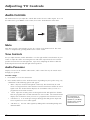
Audio Controls ........................................................................................................... 48
Mute .................................................................................................................... 48
Tone Controls ...................................................................................................... 48
Audio Processor ............................................................................................... 48
Speakers ........................................................................................................... 49
Sound Logic ..................................................................................................... 49
SAP ....................................................................................................................... 49
Optical Output ................................................................................................ 49
Audio Language ................................................................................................. 49
Using the Profiles ................................................................................... 51
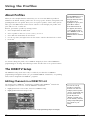
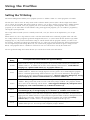
Creating User Profiles ................................................................................................ 51
About Profiles ............................................................................................................ 52
The DIRECTV Setup .................................................................................................... 52
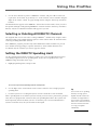
Editing Channels in a DIRECTV List .................................................................... 52
Selecting or Deleting All DIRECTV Channels ..................................................... 53
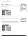
Setting the DIRECTV Spending Limit ................................................................. 53
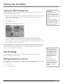
Setting the DIRECTV Rating Limit ...................................................................... 54
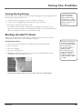
Setting the TV Rating ......................................................................................... 56
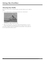
Choosing Your Profile......................................................................................... 62
Locking and Unlocking a User Profile ............................................................... 63
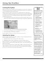
Locking the System ............................................................................................. 64
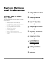
System Options and Preferences ........................................................... 65
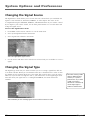
Changing the Signal Source ...................................................................................... 66
Changing the Signal Type .......................................................................................... 66
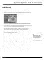
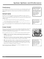
Auto Tuning ............................................................................................................... 67
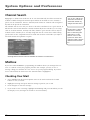
Channel Search .......................................................................................................... 68
Mailbox ....................................................................................................................... 68
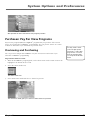
Purchases: Pay Per View Programs ............................................................................ 69
Reviewing and Canceling an Upcoming Purchase ............................................ 71

5
Table Of Contents
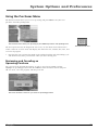
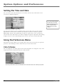
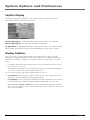
Setting the Time and Date ........................................................................................ 72
Using the Preferences Menu ..................................................................................... 72
Color Scheme ...................................................................................................... 72
Translucency ........................................................................................................ 73
Default Guide ..................................................................................................... 73
Screen Format ..................................................................................................... 73
Caption Display ................................................................................................... 74
Analog Captions ................................................................................................. 74
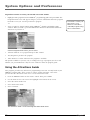
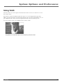
Using Fetch ................................................................................................................. 75
Getting Assistance .................................................................................. 77
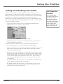
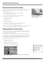
Running the Interactive Setup .................................................................................. 78
Getting Antenna Information ................................................................................... 78
Dish Pointing .............................................................................................................. 79
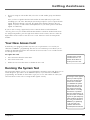
Your New Access Card ............................................................................................... 81
Running the System Test ........................................................................................... 81
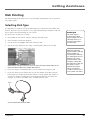
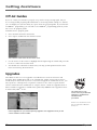
Off-Air Guides ............................................................................................................ 82
Upgrades .................................................................................................................... 82
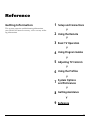
Reference ................................................................................................ 83
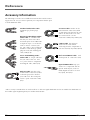
Getting Information .................................................................................................. 83
Troubleshooting ......................................................................................................... 84
Care and Cleaning ..................................................................................................... 86
FCC Registration Information ................................................................................... 87
Warranty..................................................................................................................... 88
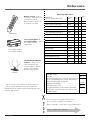
Accessory Information ............................................................................................... 90
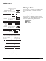
Placing an Order ........................................................................................................ 92
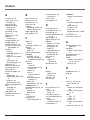
Index ...........................................................................................................................93

6
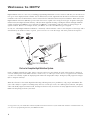
High Definition refers to a new way of sending programming information over the airwaves and into your TV. There are
two types of TV display formats available. One is ATSC format, which originated from the Advanced Television Systems
Committee. The other is NTSC format, which is named for the National Television System Committee. What makes your
High Definition Television (HDTV) special is that it has tuners capable of receiving several types of signals: analog (in
NTSC format) and digital (in ATSC format), cable (in NTSC and ATSC formats), and digital satellite and high definition
satellite (coming from DIRECTV if you subscribe to DIRECTV
®
programming
†
). This TV makes receiving all types of
signals seamless. Below is an example of how your HDTV can receive the different types of signals.
So why is it called High Definition? Definition—commonly called resolution—refers to the sharpness of the image and is
determined by the number of dots, or pixels, your screen uses to create the image. The more pixels the sharper the
image. An HDTV normally has either 1080 or 720 rows and over 1,000 columns of pixels. This results in a display of
over one million pixels. Your HDTV also has a wide screen, or “wide aspect ratio” of 16:9 as opposed to the common
4:3 ratio. It is normally capable of displaying both interlaced images (like today’s analog TVs) and progressive images
(like a computer monitor).
What this all means is that while digital broadcasting will bring many new possibilities, only people with HDTVs like
yours will actually be capable of realizing many of them. A wide aspect ratio, one million pixel resolution, CD-quality
audio with Dolby Digital surround sound, and improved interactivity are features of many digital broadcasts, and your
HDTV will help bring it all into your home.
SATELLITE
DISH ANTENNA*
TERRESTRIAL
ANTENNA
DIRECTV
SATELLITE
TOWER SENDING
ANALOG AND/OR
OR
DIRECTV HD
SATELLITE
Parts of a Complete High Definition System
TERRESTRIAL
ANTENNA
HDTV
CABLE TV
DIGITAL
SIGNALS
* The appearance of your satellite dish antenna may differ from that shown here. If your satellite dish antenna is round instead of oval,
you can receive programming from only one DIRECTV satellite.
Welcome to HDTV

7
Getting Started
This section tells you how to get your
HDTV set up and connected. It describes
the cables you will need, explains the front
and back panels, and walks you through
the steps needed to start using your TV.
➣➣➣ ➣
➣
➣
➣
➣
Reference
9
Using the Profiles
6
Adjusting TV Controls
5
4
Using Program Guides
Basic TV Operation
3
Using the Remote
2
Setup and Connections
1
System Options
and Preferences
7
Getting Assistance
8
Setup and
Connections

Setup and Connections
8 Chapter 1
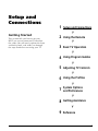
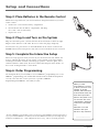
Step 1: Unpack the System
Make sure to locate the remote control and power cord.
Step 2: Connect Your TV to Other
Components
During the satellite dish antenna installation, the TV may have been connected with
just a coaxial cable for the system test. Depending on what components you have,
another connection may provide better picture and audio quality. The following
sections provide cable and connection information to help you decide what
connection is best for you.
Things to Know Before Connecting
Components
Protect Your Components from Power Surges
• Connect all components before plugging any power cords into the wall outlet.
• Always turn off the TV and other components before you connect or disconnect
any cables.
Position Cables Correctly to Avoid Audio
Hum or Interference
• Insert all cable plugs firmly into their jacks.
• Place the audio/video cables to the sides of the TV’s back panel instead of straight
down the middle after you connect your components.
• Try not to coil any twin-lead cables; keep them away from the audio/video cables
as much as possible.
• Make sure all antennas and cables are properly grounded. Refer to the safety sheet
packed with your unit.
Protect Your Components from Overheating
• Do not block ventilation holes in any of the components. Arrange the components
so that air can circulate freely.
• Do not stack components.
• Allow adequate ventilation when placing your components in a stand.
• Place an amplifier on the top shelf of the stand so that heated air rising from it will
not flow around other components.
Remote
Control
Power Cord
123
456
789
0
ON•OFF
TVVCR1
DVD
MUTE SKIP
GO BACKFETCH
GUIDE INFO
MENU CLEAR
INPUT
REVERSE PLAY FORWARD
RECORD
PIP SWAP CH CTRL WHO
STOP PAUSE
ANTENNA
AUX
DIRECTV
OK
CH
+
CH
VOL
VOL
VCR2

Setup and Connections
Chapter 1 9
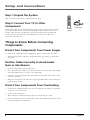
Jacks and Cables
Below is a description of the jacks and cables you can use to make connections. Note
that not all cables come with your television unit.
S-Video Jack and Cable
The S-Video jack provides the best picture quality for your system.
This jack is available on this TV and is used in conjunction with audio cables.
Remember also to connect the left and right audio cables because the S-Video jack
carries only the picture signal, not the sound.
Audio/Video Jacks and Cables (RCA-type)
The audio/video jacks provide very good picture and stereo sound quality.
Theses jacks are used for most audio/video connections between components. The
audio/video jacks are often color coded (yellow for video, red for right audio, and
white for left audio). If your component has only one input for audio (mono),
connect it to the left (white L/Mono) audio jack on the TV.
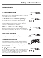
RF Jacks and Coaxial Cables (F-type)
RF jacks are necessary for reception of off-air broadcasts, cable, and DIRECTV signals.
These jacks are required for antenna or cable connections. The RF and coaxial jacks
on the TV are labeled SATELLITE IN, ANTENNA A IN, and ANTENNA B IN. An RG-6
coaxial cable is required for all satellite signal distribution.
Optical Jack and Cables
The optical cable is used for connecting a Dolby Digital receiver. If you own a
Dolby Digital receiver that uses an optical cable-type input, you can use an optical
cable to connect the TV to that receiver for the best sound quality.
Telephone Jack and Cord
The telephone line cord is required to connect your TV to a phone line. If you choose
to subscribe to DIRECTV
®
programming, a phone line dedicated and continuously
connected to the digital satellite receiver is required. The phone line connection is
used to periodically call out to DIRECTV. You will need an RJ11 type modular jack,
which is the most common type of phone jack and might look like the one pictured
here. If you don’t have a modular jack, call your local telephone company to find out
how to get one installed.
Y, P
B,
P
R
Jacks and Cable
The Y, P
B
, P
R
jacks allows you to connect an optional component video source, such
as a DVD player. This connection provides optimum quality by maintaining the
video source as three separate signals through these jacks. To ensure maximum
picture quality, use three video-grade cables for the connection.
S-Video Jack
Audio/Video Jacks
RF Jack
Digital Audio
Out Jack
Phone Jacks
Y P
B
P
R

Setup and Connections
10 Chapter 1
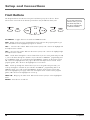
Front Buttons
The diagrams below describe the front panel and front input jacks on the TV. Please
note that the exact look of the buttons pictured here may be different from yours.
If you cannot find your
remote control, you can
use the front panel of
the TV to operate many
of the TV’s features.
INFO
TV DIRECTV
MENU OK
POWER
TV|DIRECTV Toggles between TV mode and DIRECTV mode.
INFO Brings up the on-screen channel banner. Press when in the program guide to get
more information on the highlighted program or channel.
VOL < Decreases the volume. When in the menu system, VOL < moves the highlight left
and adjusts menu controls.
VOL > Increases the volume. When in the menu system, VOL > moves the highlight right
and adjusts menu controls.
CH v Scrolls down through the current channel list. If you are in TV mode and press CH
v, you scroll down through TV channels. If you subscribe to DIRECTV
®
programming and
are in DIRECTV mode, you scroll down through DIRECTV channels. In the menu system,
CH v moves the highlight down one page at the time and adjusts menu controls. In the
program guides, CH v advances the highlight one screen down.
CH ^ Scrolls up through the channel list. If you are in TV mode and press CH^, you
scroll up through TV channels. If you subscribe to DIRECTV
®
programming and are in
DIRECTV mode, you scroll up through DIRECTV channels. In the menu system, CH^
moves the highlight up one page at the time and adjusts menu controls. In the program
guides, CH^ advances the highlight one screen up.
MENU|OK Brings up the main menu. When in the menu system, it selects highlighted
items.
POWER Turns the TV on and off.

Setup and Connections
Chapter 1 11
M
E
N
U
C
H
C
H
V
O
L
—
V
O
L
+
PO
WE
R
S
-
V
I
D
E
O
V
I
D
E
OL
/
M
O
N
O
R
A
U
D
I
O
I
N
P
U
T
4
H
E
A
D
P
H
O
N
E
PHONES VIDEO IN
L
R
AUDIO IN
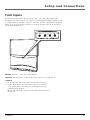
Front Inputs
The monitor has front inputs for convenience; one set of audio/video inputs and a
headphone jack. These jacks let you connect a baseband NTSC (analog) component such
as a VCR, Internet access device, game, or camcorder. Look for a hinged door and gently
lift the cover open. Please note that the exact look of the jacks or the TV pictured here
may be different from yours.
PHONES Provides a connection for headphones.
VIDEO IN Provides video connection. The video connector is usually yellow.
AUDIO IN
L Provides left audio connection. The left audio connector is
usually white. When connecting devices that use a monaural
cable, such as some camcorders, use the left input jack to get
sound from both speakers.
R Provides right audio connection. The right audio connector is
usually red.

Setup and Connections
12 Chapter 1
DIGITAL
AUDIO OUT
ANTENNA A
IN
ANTENNA B
IN
SATELLITE
IN
PHONE
JACK
ACCESS CARD
Note: You can also use the ANT B IN (or ANT A IN) for video games and switch between the two inputs using the ANTENNA
button on the remote control. When using TV games, computers, and similar products with your TV, keep the contrast at a
low setting. If a fixed (non-moving) pattern is left on the screen for long periods of time at a high contrast setting, the
image can be permanently imprinted onto the picture tubes. These types of imprints are not covered by your warranty
because they are the result of misuse.
POWER
VIDEO
AUDIO
L
R
INPUT1
INPUT2
INPUT3
S-VIDEO
AUDIO
R
L
YP
B PR
AUDIO OUTPUTS
FIXED
VARIABLE
LR L
R
EXT SPEAKERS
EXT
INT
L
R
+
+
COMPONENT VIDEO INPUT
DIGITAL
AUDIO OUT
ANTENNA A
IN
ANTENNA B
IN
SATELLITE
IN
PHONE
JACK
ACCESS CARD
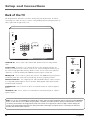
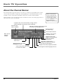
Back of the TV
The diagram below describes each of the back panel jacks found on the TV. When
connecting A/V cables, be sure to connect corresponding outputs and inputs (video to
video, right audio to right audio, etc.).
SATELLITE IN Use to connect the satellite dish antenna to the TV using an RG6
cable.
ACCESS CARD Insert the access card into the slot so your program provider can
identify you. Make sure the contacts on the access card are facing left and the top of
the card is facing right while inserting. (Refer to “New Access Card” in this manual’s
“Assistance” section for details.) The DIRECTV System requires a valid card.
PHONE JACK Use to connect a phone line to the TV. The DIRECTV System requires a
continuous phone line connection to periodically call out to program providers.
DIGITAL AUDIO OUT Use a digital optical cable (or SPDIF cable) to connect your TV
to a compatible Dolby Digital receiver or decoder. Dolby Digital offers theatre-quality
sound (six audio channels).
ANTENNA B IN Use to connect an off-air or terrestrial antenna or cable TV signal to
the TV.
ΩANTENNA A IN Use to connect a second off-air or terrestrial antenna or cable TV
signal to the TV.

Setup and Connections
Chapter 1 13
VIDEO
AUDIO
L
R
INPUT1
INPUT2
INPUT3
S-VIDEO
AUDIO
R
L
YP
B
P
R
COMPONENT VIDEO INPUT
AUDIO OUTPUTS
FIXED
VARIABLE
LR L
R
EXT SPEAKERS
EXT
INT
L
R
+
+
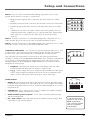
To turn the TV’s internal
speakers on and off, press
MENU on the remote
control and choose Audio.
Then choose Speakers
from the menu.
INPUT 1 Lets you connect a baseband NTSC (analog) component such as a VCR,
laserdisc player, Internet access device, or DVD player.
• VIDEO provides composite video connection. The video connector is usually
yellow.
• L AUDIO provides left audio connection. The left audio connector is usually white.
• R AUDIO provides right audio connection. The right audio connector is usually
red.
• S-VIDEO lets you connect an S-Video cable for better video quality picture to a
component with S-Video capability, such as a VCR or DVD player. When using S-
Video, make sure to connect the two audio cables as well as the S-Video
connector.
INPUT 2 Provides connection to a second NTSC (analog) video component such as a
VCR or laserdisc player. Its jacks are the same as described for INPUT 1, above.
INPUT 3 Provides connection to a third NTSC (analog) video component, such as a VCR
or laserdisc. Its jacks are the same as described for INPUTS 1 and 2.
COMPONENT VIDEO INPUT Use to connect an optional component video source, such
as a DVD player. This connection provides optimum quality. Note that it is essential to
match the color coded connectors between a compatible device and the monitor.
Grey side panels protecting against screen burn-in are not always generated when
watching a 4:3 image via the COMPONENT VIDEO INPUT jacks. Therefore, limited viewing
of a 4:3 image is recommended when no side panel are present. Also note that when
watching an image via the COMPONENT VIDEO INPUT jacks, you will not be able to
manipulate the screen format.
• AUDIO R/L The audio jacks provide stereo sound. When connected, audio
volume from the main front and rear speakers is variable audio.
• Y P
B
P
R
Unlike a single video input, component video maintains the video signal
as three separate signals through these three jacks. To ensure maximum picture
quality, use three video-grade cables for the Y, P
B
, and P
R
connections.
AUDIO OUTPUTS
• FIXED L/R Provides fixed-level audio output from the television. This audio output
is ideal for audio recording or for connecting to an A/V receiver amplifier (an auxiliary
baseband component) when you want to control the volume through the A/V receiver
instead of the TV.
• VARIABLE L/R Use to connect an A/V receiver or amplifier (an auxiliary baseband
component) for variably-controlled stereo output.
• RIGHT and LEFT Speaker Terminals Use to connect external speakers for right
and left surround sound.
• INT. / EXT. (switch) INT sends audio only to the monitor’s internal speakers. EXT
sends audio to only external speakers.

Setup and Connections
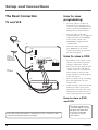
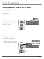
14 Chapter 1
The Basic Connection
TV and VCR
How to view
programming:
• To watch cable TV or off-air TV
programs from an antenna in this
connection, press ANTENNA on the
remote control until ANTENNA A is
displayed in the channel banner.
• To watch cable or any other
alternate RF signal, such as digital or
analog terrestrial, press ANTENNA
on the remote control until
ANTENNA B is displayed in the
channel banner.
• To watch satellite programming,
press DIRECTV on the remote
control and channel up or down to
the desired program.
How to view a VCR:
• Press INPUT on the remote control
and select the video input (in this
example, VID1) in the channel
banner. Because the digital decoder
is in the TV, not the VCR, digital
channels cannot be recorded. If an
off-air antenna is used, the VCR
output should be viewed using one
of the video inputs.
• If you’ve already set up auto tuning,
press the VCR1 button on your
remote control.
• NOTE: Viewing a VCR while in AIR
mode may result in poor picture
performance. Instead, select System
Options from the main menu, then
select Signal Type and select Cable.
How to view a DVD
and VCR:
DIGITAL
AUDIO OUT
ANTENNA A
IN
ANTENNA B
IN
SATELLITE
IN
PHONE
JACK
ACCESS CARD
VCR
IN FROM ANT
OUT TO TV
OUT
VIDEO
L
R
CH3
CH4
TV
SATELLITE
DISH ANTENNA
CABLE OR
OFF-AIR ANTENNA
L
R
CABLE OR
ANY ALTERNATE
RF SIGNAL, SUCH AS
A DIGITAL OR ANALOG
TERRESTRIAL ANTENNA
POWER
VIDEO
AUDIO
L
R
INPUT1
INPUT2
INPUT3
S-VIDEO
AUDIO
R
L
YP
B
P
R
AUDIO OUTPUTS
FIXED
VARIABL E
LR L
R
EXT SPEAKERS
EXT
INT
L
R
+
+
COMPONENT VIDEO INPUT
The ANT B and ANT A jacks
can receive digital or analog
RF signals. The illustrations
here are recommended
connections in a cable
environment.
Some cable systems may require a “conversion box.” If so, consult your cable
company’s box tuning instructions for details.

Setup and Connections
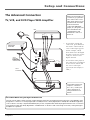
Chapter 1 15
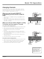
The Advanced Connection
TV, VCR, and DVD Player With Amplifier
DIGITAL
AUDIO OUT
ANTENNA A
IN
ANTENNA B
IN
SATELLITE
IN
PHONE
JACK
ACCESS CARD
VCR 1
ANT. IN
RF OUT
OUT
VIDEO
L
R
CH3
CH4
TV
SATELLITE
DISH ANTENNA
CABLE OR
OFF-AIR ANTENNA
DVD
OUT
VIDEO
L
R
S-VIDEO
AMPLIFIER WITH
OPTICAL INPUT
DIGITAL
AUDIO IN
L
R
POWER
VIDEO
AUDIO
L
R
INPUT1
INPUT2
INPUT3
S-VIDEO
AUDIO
R
L
YP
B
P
R
AUDIO OUTPUTS
FIXED
VARIABLE
LR L
R
EXT SPEAKERS
EXT
INT
L
R
+
+
COMPONENT VIDEO INPUT
CABLE OR
ANY ALTERNATE
RF SIGNAL, SUCH AS
A DIGITAL OR ANALOG
TERRESTRIAL ANTENNA
• To watch the VCR in this
connection, press INPUT on
the remote control until the
correct video input appears
(in this example, VID3).
Note that because the digital
decoder is in the TV, not the
VCR, you cannot record
digital channels.
• To watch the DVD player in
this connection, press INPUT
on the remote control until
the correct video input
appears (in this example, S-
VID1 ).
Please Read Before Using the Digital Audio Out Jack
This TV’s optical digital output jack fully complies with the international standard governing this type of jack (IEC958), and is
designed for connection to a Dolby Digital (AC-3 or PCM) receiver or Dolby Digital (AC-3 or PCM) decoder. Older equipment,
some of which is not fully compliant with IEC958, may not be compatible with the Dolby Digital bitstream. Such a connection
using anything other than Dolby Digital AC-3 or PCM receiver or decoder could create a high noise level, causing damage to
headphones or speakers.
Some cable systems may
require a “conversion
box.” If so, consult your
cable company’s box
tuning instructions for
details.
After you have made your
connections, program the
TV to tune to the correct
video input channel to see
and hear audio and video
from the attached
component (VCR, DVD
player, etc.). Program your
TV as described in the
“System Options and
Preferences” section of
this book.

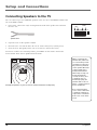
Setup and Connections
16 Chapter 1
LEFT RIGHT
TELEVISION
Arrange the speakers in your TV room to achieve maximum sound quality.
Connecting Speakers to the TV
You can connect up to two additional speakers to the TV: one to the RIGHT terminal, and
one to the LEFT terminal.
1. If necessary, remove the vinyl covering from the ends of the speaker wire and twist
the wire core.
When connecting the
speaker wire, make sure
you connect the positive
(+) terminal on the TV to
the positive (+) terminal
on the speaker. One side
of the speaker wire is
usually marked with a
white stripe to help you
match the terminals
correctly. If the (+) and
(-) terminals are not
matched properly, the
speakers will not be “in
phase,” causing reduction
in bass frequencies.
Do not allow the wire
core to touch other wires
or terminals. Damage to
components could result
if the cores of two wires
touch.
Speaker wire
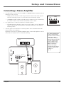
AUDIO OUTPUTS
FIXED
VARIABLE
LR L
R
EXT SPEAKERS
EXT
INT
L
R
+
+
2. Open the lever on the speaker terminal.
3. Insert the wire core into the hole. Be sure to connect the (+) to (+) and (-) to (-).
4. Close the lever. Pull gently on the wire to see that it’s connected securely.
To turn on or off the TV’s internal speakers, press MENU on the remote control and
choose Audio. Then choose Speakers from the menu.
Page is loading ...
Page is loading ...
Page is loading ...
Page is loading ...
Page is loading ...
Page is loading ...
Page is loading ...
Page is loading ...
Page is loading ...
Page is loading ...
Page is loading ...
Page is loading ...
Page is loading ...
Page is loading ...
Page is loading ...
Page is loading ...
Page is loading ...
Page is loading ...
Page is loading ...
Page is loading ...
Page is loading ...
Page is loading ...
Page is loading ...
Page is loading ...
Page is loading ...
Page is loading ...
Page is loading ...
Page is loading ...
Page is loading ...
Page is loading ...
Page is loading ...
Page is loading ...
Page is loading ...
Page is loading ...
Page is loading ...
Page is loading ...
Page is loading ...
Page is loading ...
Page is loading ...
Page is loading ...
Page is loading ...
Page is loading ...
Page is loading ...
Page is loading ...
Page is loading ...
Page is loading ...
Page is loading ...
Page is loading ...
Page is loading ...
Page is loading ...
Page is loading ...
Page is loading ...
Page is loading ...
Page is loading ...
Page is loading ...
Page is loading ...
Page is loading ...
Page is loading ...
Page is loading ...
Page is loading ...
Page is loading ...
Page is loading ...
Page is loading ...
Page is loading ...
Page is loading ...
Page is loading ...
Page is loading ...
Page is loading ...
Page is loading ...
Page is loading ...
Page is loading ...
Page is loading ...
Page is loading ...
Page is loading ...
Page is loading ...
Page is loading ...
Page is loading ...
Page is loading ...
Page is loading ...
Page is loading ...
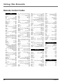
-
 1
1
-
 2
2
-
 3
3
-
 4
4
-
 5
5
-
 6
6
-
 7
7
-
 8
8
-
 9
9
-
 10
10
-
 11
11
-
 12
12
-
 13
13
-
 14
14
-
 15
15
-
 16
16
-
 17
17
-
 18
18
-
 19
19
-
 20
20
-
 21
21
-
 22
22
-
 23
23
-
 24
24
-
 25
25
-
 26
26
-
 27
27
-
 28
28
-
 29
29
-
 30
30
-
 31
31
-
 32
32
-
 33
33
-
 34
34
-
 35
35
-
 36
36
-
 37
37
-
 38
38
-
 39
39
-
 40
40
-
 41
41
-
 42
42
-
 43
43
-
 44
44
-
 45
45
-
 46
46
-
 47
47
-
 48
48
-
 49
49
-
 50
50
-
 51
51
-
 52
52
-
 53
53
-
 54
54
-
 55
55
-
 56
56
-
 57
57
-
 58
58
-
 59
59
-
 60
60
-
 61
61
-
 62
62
-
 63
63
-
 64
64
-
 65
65
-
 66
66
-
 67
67
-
 68
68
-
 69
69
-
 70
70
-
 71
71
-
 72
72
-
 73
73
-
 74
74
-
 75
75
-
 76
76
-
 77
77
-
 78
78
-
 79
79
-
 80
80
-
 81
81
-
 82
82
-
 83
83
-
 84
84
-
 85
85
-
 86
86
-
 87
87
-
 88
88
-
 89
89
-
 90
90
-
 91
91
-
 92
92
-
 93
93
-
 94
94
-
 95
95
-
 96
96
-
 97
97
-
 98
98
-
 99
99
-
 100
100


DirecTV HD65W20 Receiver User manual
- Category
- LCD TVs
- Type
- User manual
- This manual is also suitable for
Ask a question and I''ll find the answer in the document
Finding information in a document is now easier with AI
Related papers
-
DirecTV DSX PS61000 Receiver User manual
-
-
-
DirecTV HUGHES/ HTL-HD User manual
-
Toshiba DW65X91 HD Projection TV User manual
-
-
DirecTV H10 User manual
-
-
-
