Page is loading ...

L8542103
02/2013 Rev. 1
BULL
10M-15M-20M
APRICANCELLO SCORREVOLE ELETTROMECCANICO
ELECTROMECHANICAL SLIDING GATE OPENER
ELEKTROMECHANISCHE AUTOMATION FÜR SCHIEBEGITTER
AUTOMATISATION ÉLECTROMÉCANIQUE POUR GRILLES COULISSANTES
ABRECANCELA ELECTROMECANICO PARA CORREDERAS
ELEKTROMECHANICZNY, POSUWOWY OTWIERACZ BRAM
Libro istruzioni e catalogo ricambi
Operating instructions and spare parts catalogue
Betriebsanleitung und Ersatzteilliste
Livret d’instructions et catalogue des pieces de rechange
Libro de instrucciones y catálogo de recambios
Książeczka z instrukcjami i katalog części wymiennych
UNIONE NAZIONALE COSTRUTTORI
AUTOMATISMI PER CANCELLI, PORTE
SERRANDE ED AFFINI

2
Dichiarazione CE di Conformità
Dichiarazione in accordo alle Direttive 2004/108/CE(EMC); 2006/95/CE(LVD)
Fabbricante: Automatismi Benincà SpA
Indirizzo: Via Capitello, 45 - 36066 Sandrigo (VI) - Italia
Dichiara che il prodotto:
Attuatore elettromeccanico 24Vdc per cancelli scorrevoli modello:
BULL 10M - BULL 15M - BULL 20M.
è conforme alle condizioni delle seguenti Direttive CE:
• DIRETTIVA 2004/108/CE DEL PARLAMENTO EUROPEO E DEL CONSIGLIO del 15 dicembre 2004 concernente il ravvicinamento delle legislazioni
degli Stati membri relative alla compatibilità elettromagnetica e che abroga la direttiva 89/336/CEE, secondo le seguenti norme armonizzate:
EN 61000-6-2:2005, EN 61000-6-3:2007.
• DIRETTIVA 2006/95/CE DEL PARLAMENTO EUROPEO E DEL CONSIGLIO del 12 dicembre 2006 concernente il ravvicinamento delle legislazioni
degli Stati membri relative al materiale elettrico destinato ad essere adoperato entro taluni limiti di tensione, secondo le seguenti norme armonizzate:
EN 60335-1:2002 + A1:2004 + A11:2004 + A12:2006 + A2:2006 + A13:2008; EN 60335-2-103:2003.
• DIRETTIVA 2006/42/CE DEL PARLAMENTO EUROPEO E DEL CONSIGLIO GHOPDJJLRUHODWLYDDOOHPDFFKLQHHFKHPRGL¿FDODGLUHWWLYD
95/16/CE, rispettando i requisiti per le “quasi macchine”, secondo la seguente norma: EN13241-1:2003.
• Automatismi Benincà SpA dichiara, inoltre, che la documentazione tecnica pertinente è stata compilata in conformità all’allegato VII B della direttiva
2006/42/CE e che sono stati rispettati i seguenti requisiti essenziali: 1.1.1 - 1.1.2 - 1.1.3 - 1.1.5 - 1.2.1 - 1.2.3 - 1.2.6 - 1.3.1 - 1.3.2 - 1.3.3 - 1.3.4 - 1.3.7 - 1.3.9
- 1.5.1 - 1.5.2 - 1.5.4 - 1.5.5 - 1.5.6 - 1.5.7 - 1.5.8 - 1.5.10 - 1.5.11 - 1.5.13 - 1.6.1 - 1.6.2 - 1.6.4 - 1.7.2 - 1.7.4 - 1.7.4.1 - 1.7.4.2 - 1.7.4.3.
• Il produttore si impegna a trasmettere alle autorità nazionali, in risposta ad una motivata richiesta, le informazioni pertinenti sulla “quasi macchina”. L’impegno
comprende le modalità di trasmissione e lascia impregiudicati i diritti di proprietà intellettuale del fabbricante della “quasi macchina”.
6LFRPXQLFDFKHOD³TXDVLPDFFKLQD´QRQGHYHHVVHUHPHVVDLQVHUYL]LR¿QFKpODPDFFKLQD¿QDOHLQFXLGHYHHVVHUHLQFRUSRUDWDQRQqVWDWDGLFKLDUDWDFRQ-
forme, se del caso, alle disposizioni della direttiva 2006/42/CE.
• Inoltre il prodotto, limitatamente alle parti applicabili, risulta conforme alle seguenti norme:
EN 12445:2002, EN 12453:2002, EN 12978:2003.
Benincà Luigi, Responsabile legale.
Sandrigo, 02/11/2010.
EC Declaration of Conformity
Directive 2004/108/EC(EMC); 2006/95/EC (LVD)
Manufacturer: Automatismi Benincà SpA.
Address: Via Capitello, 45 - 36066 Sandrigo (VI) – Italy
It is hereby stated that the product
automatic system 24Vdc for sliding gates
BULL 10M - BULL 15M - BULL 20M.
is compliant with provisions set forth in the following EC Directives:
- DIRECTIVE 2004/108/EC OF THE EUROPEAN PARLIAMENT AND OF THE COUNCIL of 15 December 2004, on the harmonisation of the laws of
Member States relating to electromagnetic compatibility and which cancels Directive 89/336/EEC, according to the following harmonised regulations: EN 61000-
6-2:2005, EN 61000-6-3:2007.
- DIRECTIVE 2006/95/EC OF THE EUROPEAN PARLIAMENT AND OF THE COUNCIL of 12 December 2006, on the harmonisation of the laws of
Member States relating to electrical equipment designed for use with certain voltage limits, according to the following harmonised regulations: EN 60335-1:2002
+ A1:2004 + A11:2004 + A12:2006 + A2:2006 + A13:2008; EN 60335-2-103:2003.
- DIRECTIVE 2006/42/EC OF THE EUROPEAN PARLIAMENT AND OF THE COUNCIL of 17 May 2006, on machinery, which amends Directive
95/16/EC, and complies with the requisites for the “partly completed machinery (almost machinery)” set forth in the EN13241-1:2003 regulation.
• Moreover, Automatismi Benincà SpA declares that the pertaining technical documentation has been drawn up in compliance with Attachment VII B of the
2006/42/ EC Directive and that the following requirements have been complied with: 1.1.1 - 1.1.2 - 1.1.3 - 1.1.5 - 1.2.1 - 1.2.3 - 1.2.6 - 1.3.1 - 1.3.2 - 1.3.3 - 1.3.4
- 1.3.7 - 1.3.9 - 1.5.1 - 1.5.2 - 1.5.4 - 1.5.5 - 1.5.6 - 1.5.7 - 1.5.8 - 1.5.10 - 1.5.11 - 1.5.13 - 1.6.1 - 1.6.2 - 1.6.4 - 1.7.2 - 1.7.4 - 1.7.4.1 - 1.7.4.2 - 1.7.4.3.
• The manufacturer undertakes that information on the “partly completed machinery” will be sent to domestic authorities. Transmission ways are also included
in the undertaking, and the Manufacturer’s intellectual property rights of the “almost machinery” are respected.
,WLVKLJKOLJKWHGWKDWFRPPLVVLRQLQJRIWKH³SDUWO\FRPSOHWHGPDFKLQHU\´VKDOOQRWEHSURYLGHGXQWLOWKH¿QDOPDFKLQHU\LQZKLFKLWVKRXOGEHLQFRUSRUDWHGLV
declared compliant, if applicable, with provisions set forth in the Directive 2006/42/EC on Machinery.
• Moreover, the product, as applicable, is compliant with the following regulations:
EN 12445:2002, EN 12453:2002, EN 12978:2003.
%HQLQFj/XLJL/HJDO2I¿FHU
Sandrigo, 22 November 2010.

5
Dati tecnici
Technical data Technische Daten
BULL 10M BULL 15M BULL 20M
Alimentazione
Potenza assorbita
Assorbimento
Coppia
Intermittenza di lavoro
Grado di protezione
Temp. funzionamento
Peso max. cancello
Modulo cremagliera
Velocità apertura
Condensatore
Rumorosità
Lubrificazione
Peso
Feed
Absorbed power
Absorption
Torque
Operating jogging
Protection class
Working temperature
Max. gate weight
Rack modulus
Opening speed
Capacitor
Noise level
Lubrication
Weight
Speisung
Aufgenom. Leistung
Verbrauch
Kräftepaar
Betriebsintermittenz
Schutzklasse
Betriebstemperatur
Gittersgewicht max.
Modul der Zahnstange
Öffnungsgeschwindigkeit
Kondensator
Geräuschentwicklung
Schmierung
Gewicht
230Vac 50Hz
350 W
1,6 A
27 Nm
40%
IP44
-20°C / +50°C
1000kg
M4
10,5m/min
20 µF
<70 dB
Agip GR MU EP/2
18,7 kg
230Vac 50Hz
410 W
2,5 A
45 Nm
60%
IP44
-20°C / +50°C
1500kg
M4
10,5m/min
25 µF
<70 dB
Agip GR MU EP/2
20,1 kg
230Vac 50Hz
506 W
2,9A
60 Nm
40%
IP44
-20°C / +50°C
2000kg
M4
10,5m/min
31,5 µF
<70 dB
Agip GR MU EP/2
21,6 kg
Donnees technique Datos técnicos
Dane techniczne
BULL 10M BULL 15M BULL 20M
Alimentation
Puissance absorbée
Absorption
Couple
Intermittence de travail
Degré de protection
Temp. fonctionnement
Poids max. portail
Module de la crémaillère
Vitesse d'ouverture
Condensateur
Bruit
Lubrification
Poids
Alimentación
Consumo de potencia
Absorción
Par
Intermitencia de trabajo
Grado de protección
Temp. funcionamiento
Peso máx. de la cancela
Módulo de cremallera
Velocidad de apertura
Condensador
Ruido
Lubrificación
Peso
Zasilanie
Natężenie
Pobór mocy
Moment obrotowy
Rodzaj pracy
Stopień ochrony
Temp. podczas pracy
Ciężar max. bramy
Typ listwy zębatej
Prędkość otwieraia
Kondensator
Max. halas
Smarowanie
Ciężar
230Vac 50Hz
350 W
1,6 A
27 Nm
40%
IP44
-20°C / +50°C
1000kg
M4
10,5m/min
20 µF
<70 dB
Agip GR MU EP/2
18,7 kg
230Vac 50Hz
410 W
2,5 A
45 Nm
60%
IP44
-20°C / +50°C
1500kg
M4
10,5m/min
25 µF
<70 dB
Agip GR MU EP/2
20,1 kg
230Vac 50Hz
506 W
2,9A
60 Nm
40%
IP44
-20°C / +50°C
2000kg
M4
10,5m/min
31,5 µF
<70 dB
Agip GR MU EP/2
21,6 kg
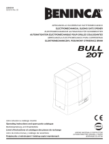
200
245
BULL10M/15M: 340
BULL 20M: 395
316
BULL10M/15M: 340
BULL 20M: 395
Dimensioni d’ingombro - Overall dimensions
Abmessungen - Dimensions d’encombrement
Dimensiones exteriores - Wymiary gabarytowe
300
215

6
180
318
Fig.1
40
Tubo corrugato
Grooved tube
Faltenrohr
Passe-câbles tubulaire
Tubo corrugado
Rurka sprężysta
IMPORTANTE: Rispettare questa quota!
IMPORTANT NOTE: Keep to this dimension!
WICHTIG: Dieses Maß beachten!
IMPORTANT: Respectez ce quota!
IMPORTANTE: ¡Respetar esta cota!
WAŻNE: Zachować ten wymiar!
N°4 tasselli Ø10/120mm
4 screw anchors Ø10/120mm
4 Dübel Ø10/120mm
N°4 chevilles Ø10/120mm
N°4 tacos Ø10/120mm
4 kołki Ø10/120 mm
N°4 fori Ø10
4 holes Ø10
4 Löcher Ø10
N°4 trous Ø10
N°4 agujeros Ø10
4 otwory Ø10
Fig.2
Fissaggio diretto su fondo in cemento esistente
Direct fitting on the already existing base in concrete
Direkte Befestigung an einem vorhandenen Betonuntergrund
Ancrage direct sur fond en ciment préexistant
Fijación directa sobre fondo de cemento existente
Bezpośrednie zamocowanie w istniejącym
fundamencie betonowym

7
Fig.4
Scavo per getto di calcestruzzo
Hole for concrete layer
Baugrube für Bettonierung
Cavage pour coulée de béton
Excavación para vaciado de hormigón
Wykopy do wylania betonu
N°4 rosette 11x30
4 washers 11x30
4 Scheiben 11x30
N°4 rondelles 11x30
N°4 arandelas 11x30
4 podkładki 11x30
N°4 dadi M10
4 nuts M10
4 Muttern M10
N°4 écrous M10
N°4 tuercas M10
4 nakrętki M10
N°4 tirafondi filettati M10 annegati nel calcestruzzo
4 M10 threaded stretcher bolts immersed in concrete
4 Zugbolzen mit Gewinde M10 im Beton eingebettet
N°4 tire-fonds filetés M10 noyés dans le béton
N°4 tirafondos con rosca M10 ahogados en el hormigón
4 odciągi gwintowane M10 zakotwiczone w betonie
Fig.3
100mm + X
X
N°4 barre M10
4 bars M10
4 Stäbe M10
N°4 barres M10
N°4 espárragos M10
4 drążki M10
N°4 rosette
4 washers
4 Scheiben
N°4 rondelles
N°4 arandelas
4 podkładki
A
N°4 tasselli per barre M10
4 screw anchors for bars M10
4 Dübel für Stäbe M10
N°4 chevilles pour barres M10
N°4 tacos para espárragos M10
4 płytki do drążków M10
B
N°4 rosette
4 washers
4 Scheiben
N°4 rondelles
N°4 arandelas
4 podkładki
Fissaggio con regolazione su fondo in cemento esistente
Fitting with adjustment on the already existing base in concrete
Befestigung an einem vorhandenen Betonuntergrund
und Einstellung
Ancrage avec réglage sur fond en ciment préexistant
Fijación con regulación sobre fondo de cemento
existente
Zamocowanie z możliwością regulacji w
istniejącym fundamencie betonowym
Fissaggio con tirafondi su getto in calcestruzzo
Fitting with stretcher bolts on concrete layer
Befestigung durch Zugbolzen an einer Bettonierung
Ancrage avec tire-fonds sur coulée de béton
Fijación con tirafondos sobre vaciado de hormigón
Zamocowanie z odciągiem w płycie betonowej
Fig.3
N°4 dadi M10
4 nuts M10
4 Muttern M10
N°4 écrous M10
N°4 tuercas M10
4 nakrętki M10

8
Fig.6
MIN = 0 mm
MAX = 20 mm
MIN =120 mm
MAX = 140 mm
Posizionare in altezza rispetto alla cremagliera e
mettere a livello.
Place higher than rack and level.
Senkrecht gegenüber der Zahnstange positionieren
und ausrichten.
Réglage en hauteur par rapport à la cremaillére et
mise en niveau horizontal.
Posicionar en altura con respecto a la cremallera y
apretar.
Ustawić na wskazanej wysokości względem zę-
batki i w pozycji poziomej.
Fig.5
Attendere il consolidamento del getto di calcestruzzo, quindi rimuovere i dadi "D"
e le rondelle "R" fascia larga 11x30 e portarli sotto la piastra per consentire le
regolazioni in altezza dell'attuatore.
Wait for hardening of the concrete layer, then remove the nuts “D” and the
11x30 large band washers “R”, move them under the plate to allow for the
actuator adjustment in height.
Abwarten bis der Beton ausgehärtet ist, dann die Muttern „D“ und die breiten
Scheiben „R“ 11x30 abnehmen und unter die Platte bringen, um die Höhe des
Aktuators einstellen zu können.
Attendez le durcissement de la coulée de béton et retirez les écrous “D” et
les rondelles “R” bande large 11x30, pèortez-les sous la plaque pour permet-
tre les réglages en hauteur de l’actuateur.
Esperar que se consolide el vaciado de hormigón, seguidamente quitar las tuercas
“D” y las arandelas “R” faja larga 11x30 y ponerlas debajo de la placa para consentir
las regulaciones de altura del actuador.
Odczekać na utwardzenie wylewu betonowego, a następnie odmontować na-
krętki „D” oraz podkładki ”R” szerokopasmowe 11x30 i umieścić je pod płytą
w celu umożliwienia regulacji wysokości siłownika.
D
R
R
D

10
A
S
1 ÷ 3 cm
G
Fig.11
Fig.10
Finecorsa appena premuto.
Just pressed limit stop.
Gedrückter Endanschlag.
Fin de course à peine appuyé.
Final de carrera apenas presionado.
Krańcówka dopiero co naciśnięta.
N.B.: La staffa del finecorsa deve essere posizionata in modo tale da permettere
l’arresto del cancello senza che questo vada a sbattere contro l’arresto meccanico
N.b. The limit stop flask must be positioned to ensure that the gate stops without
knocking against the mechanical stop.
Der Endanschlagtbügel muß so positioniert werden, daß die Sperre des Gitters ohne
das Flattern des Schiebegitters gegen den Endschalter A erfolgen kann.
N.B. L’étrier de fin de course doit être positionné de façon à pouvoir arrêter le
portail, sans qu’il aille bûter sur le fin de course mécanique.
NOTA: La pletina del final de carrera debe ser colocada de tal forma que permita la
parada de la cancela sin que ésta vaya a tocar con el tope mecánico.
Uwaga: Zaczep krańcówki musi być w pozycji takiej by możliwe było zatrzymanie
bramy niedopuszczając do jej zderzenia z zaporą mechaniczną.
C
L

11
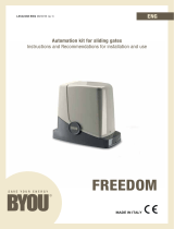
Fig.12
8
7
4
1
2
3
3 x 1,5 min
Legenda:
1 Motoriduttore con centralina incorporata BULL
2 Cremagliera RI.M4F/RI.M4Z
3 Staffe dei finecorsa
4 Fotocellule
5 Fermi meccanici
6 Selettore a chiave o tastiera digitale
7 Lampeggiante
8 Antenna
Legenda:
1 Ratio-motor complete with gear case BULL
2 Rack RI.M4F/RI.M4Z
3 Limit stop flasks
4 Photo-electric cells
5 Mechanical stop
6 Key or digital keyboard selector
7 Blinker
8 Antenna
Zeichenerklärung:
1 Drehzahlminderer mit eingebauter Schaltanlage BULL
2 Zahnstange RI.M4F/RI.M4Z
3 Endschlagbügel
4 Fotozelle
5 Mech. Endanschlag
6 Schlüssel-Selektor oder Digital-Tastatur
7 Blinklicht
8 Antenne
Légende:
1 Motoréducteur avec circuit intégré BULL
2 Cremaillére RI.M4F/RI.M4Z
3 Etriers de fin de course
4 Photocellules
5 Bûtée mécanique
6 Sélecteur à clef ou à clavier
7 Feu clignotant
8 Antenne
Leyenda:
1 Motorreductor con centralita incorporada BULL
2 Cremallera RI.M4F/RI.M4Z
3 Pletinas de los finales de carrera
4 Fotocélulas
5 Topes mecánicos
6 Selector a llave o teclado digital
7 Relampagueador
8 Antena
Objaśnienia:
1 Siłownik z wbudowaną centralką BULL
2 Zębatka RI.M4F/RI.M4Z
3 Zawieszki krańcowych wylączników posuwu
4 Fotokomórki
5 Chwytaki mechaniczne
6 Przełącznik kluczowy lub panel sterujący
7 Światło migające
8 Antena
2 x 1,5
RG 58
5
4 x 0,35
230V
4
6
5
2 x 0,35
3 x 0,35
40÷60 cm dal suolo (secondo normativa vigente)
40÷60 cm from the ground (according to standard in force)
40÷60 cm aus dem Boden (nach geltende Normen)
40÷60 cm du sol (suivant les normes en vigueur)
40÷60 cm del suelo (según normativa vigente)
40÷60 cm od powierzchni ziemi (według obowiązującej normy)
Max 10 cm dalla zona di convogliamento
Max. 10 cm from the conveyance area
Max. 10 cm von der Zuführungszone
Maximum 10 cm de la zone d’acheminement
Max. 10 cm de la zona de desplazamiento
Max. 10 cm od strefy ciągnięcia

14
Introduction
Thank you for choosing our BULL ratiomotor. All items in the wide Benincà production range are the result
of twenty-years’ experience in the automatism sector and of continuous research for new materials and ad-
vanced technologies. We are, therefore, in the position to offer higly reliable products that due to their power,
effectiveness and useful life, fully satisfy the final user’s requirements.
All our products are manufactured to the existing standard and are covered by warranty.
Possible injury to people or accidents caused by defects in construction are covered by a civil liability policy
drawn up with one of the major insurance companies.
1. General information
For an efficient operation of the sliding automatic mechanism, the gate must have the following features:
- The guide rail and its wheels must be suitable in size and mantained to prevent gate from excessive sliding
friction.
- When running, gate must not rock excessively.
- Opening and closing stroke must be regulated by a mechanical limit stop (to safety standard in force).
2. General features
Automation with single-phase power supply for sliding gates, available in three models:
BULL 10M for gates with max weight of 1000 Kg
BULL 15M for gates with max weight of 1500 Kg
BULL 20M for gates with max weight of 2000 Kg
The small and elegant design enbloc BULL consists of an aluminium unit containing the motor and irreversible
reduction unit, realized with high-grade materials.
The BULL has a spring-operated limit-switch.
A personalized key emergency release enables manual gate operation in the event of power failure.
Anti-crash safety is ensured by an electronic device (encoder), which detects the presence of any obstacle.
3. Installation of the foundation plate
Dimensions of the foundation plate are shown in Fig. 1.
It is essential to keep the distance from the rack, in order to position and remove the actuator once the rack
is fitted to the gate leaf.
The types of fittings of the foundation plate are mainly the following:
1 Installation without adjustment in height on the already existing base in concrete (Fig.2).
By using the plate as drilling template, drill 4 holes Ø10mm, and insert the steel threaded screw anchors,
Ø10x120mm, similar to those shown in Fig. 2.
Lock the actuator directly to floor, as indicated in Fig.7.
2 Installation with adjustment in height on the already existing base in concrete (Fig.3).
By using the plate as drilling template, drill 4 holes, and insert the Ø 10mm steel screw anchors for threaded
bars.
Tighten the 4 threaded bars, M10/120mm, and anchor the screw anchors by tightening the nuts “B” to floor
with the corresponding washers.
With reference to Fig. 3, position the foundation plate by means of the adjustment nuts “A”. After carrying out
the required regulations, position the motor as shown in Fig.6, and lock it, as indicated in Fig.7.
3 Installation with adjustment in height on concrete base.
With reference to Fig. 4, fit the stretcher bolts on the foundation plate and provide for a hole of adequate size.
Immerse the stretcher bolts in concrete, then remove the nuts “D” and the 11x30, large band washers “R”.
Move them under the plate to allow for regulations in height of the actuator (Fig. 5).
Carry out the regulations shown in Fig. 6 and lock the motor as indicated in Fig.7.
CAUTION: apart from the fitting modality used, carefully check that the actuator is steadily positioned
and the materials are suited to the intended use.
4. Rack fixing
Iron rack, 12x30mm.
Position the spacers D by welding or fit them to the gate with screws at 130/150mm height from the centre
line of the slot used for fitting to the base on which the foundation plate is to be fixed.

15
Keep the pitch of teeth between the two parts of the rack; the joining with another piece of rack would make
it easier to achieve (see Fig.8)
Secure the rack with the screws V making sure, once the actuator has been installed, that between rack and
the drive gear there is always approx. 1mm clearance (see Fig.9); to get this clearance use the slots on the rack.
5. Limit stop flask positioning (see Fig.10)
Open manually the gate and leave approximately of 1÷3cm, depending on gate weight, between gate and
positive mechanical stop A; tighten the limit stop flask S with the grains G to press the limit stop micro. Repeat
the sequence with closing gate.
6. Manual operation (see Fig.11)
In the event of power failure or malfunction, to manually operate the gate proceed as follows:
- After inserting the customized key C, turn it anti-clockwise and pull the lever L.
- The geared motor is unlocked and the gate can be moved by hand.
- To return to the normal operating mode, close the lever L again and manually activate the gate until it is
geared.
7. Wire diagram
For the wire connections of the system and to adjust the operating modes, please refer to the Instruction
Manual of the control unit.
In particular, the anti-crash device (encoder) should be adjusted according to regulations in force.
Please remember that the device should be earthed by means of the appropriate terminal.
The civil liability policy, which covers possible injuries to people or accidents caused by defects in construc-
tion, requires the system to be to existing standard and to use original Benincà accessories.

24
Pos. Denominazione - Description - Bezeichnung - Dénomination - Denominación - Określenie Cod.
A
Motore BULL10M
Motor BULL 10M Motor BULL10M Moteur BULL10M Motor BULL10M Silnik BULL10M
9686297
Motore BULL15M
Motor BULL15M Motor BULL15M Moteur BULL15M Motor BULL15M Silnik BULL15M
9686298
Motore BULL 20M
Motor BULL20M Motor BULL20M Moteur BULL20M Motor BULL20M Silnik BULL 20M
9686299
B
Copertura 10/15M
Cover 10/15M Deckel 10/15M
Couvercle 10/15M
Tapa 10/15M Karter 10/15M
9686331
Copertura 20M
Cover 20M Deckel 20M Couvercle 18M Tapa 20M Karter 20M
9686330
1
Carter motore
Motor cover Motor Deckel Couvercle mot. Tapa motor Karter silnik
9686327
2
Leva di sblocco
Release lever Hebel Levier Pal. de desbloq. Dźwignia odrygl.
9686328
3
Finecorsa
Limit stop Endschalter Fin de course Final de carrera Krańcówka
9686329
4
Encoder Encoder Encoder Encodeur Encoder Enkoder
9686332
5
Guarnizione
Gasket Dichtung Guarniture Junta Uszczelka
9686333
6
Albero di uscita
Output shaft Antriebszapfen Arbre Eje de salida Wał wyjściowy
9686334
7
Flangia Flange Flansch Flasque . Brida Kołnierz
9686335
8
Pignone M4
Gear M4 Zahnrad M4 Engrenage M4 Piñon M4
Wał napędzający M4
9686032
9
Centrale
Control Unit Schaltanlage Centrale électr. Central Centralka elektr.
9686336
10
Blister
Blister Blister Blister Blister Blister
9686337
3
9
A
2
4
5
6
1
B
7
8
10

26
BULL
User’s handbook
Safety measures
• Do not stand within the gate movement area.
• Children must not play with controls and near the gate.
• In the event of malfunctions, do not attempt to repair the failure but contact the specialised personnel.
Manual and emergency manoeuvre
In the event of power failure or malfunction, to manually operate the gate proceed as follows:
• After inserting the customized key C, turn it anti-clockwise and pull the lever L.
• The geared motor is unlocked and the gate can be moved by hand.
• To return to the normal operating mode, close the lever L again and manually activate the gate until it is
geared.
Maintenance
• Every month check the good operation of the emergency manual release.
• It is mandatory not to carry out extraordinary maintenance or repairs as accidents may be caused.These
operations must be carried out by qualified personnel only.
• The operator is maintenance free but it is necessary to check periodically if the safety devices and the other
components of the automation system work properly. Wear and tear of some components could cause
dangers.
Waste disposal
If the product must be dismantled, it must be disposed according to regulations in force regarding the dif-
ferentiated waste disposal and the recycling of components (metals, plastics, electric cables, etc..). For this
operation it is advisable to call your installer or a specialised company.
Warning
All Benincá products are covered by insurance policy for any possible damages to objects and persons caused
by construction faults under condition that the entire system be marked CE and only Benincá parts be used.
C
L
/