
MultiModem
®
Wireless EDGE, GPRS, CDMA Modems
with Ethernet Interface
User Guide

Copyright and Technical Support
Multi-Tech Systems, Inc. MultiModem Wireless Modem with Ethernet Interface (S000375B) 2
User Guide
MultiModem® Wireless EDGE, GPRS, and CDMA Modems with an Ethernet Interface
MTCBA-E-EN, MTCBA-G-EN-Fx, MTCBA-C-EN-Nx
S000375C, Revision C
Copyright
This publication may not be reproduced, in whole or in part, without prior expressed written permission from Multi-
Tech Systems, Inc. All rights reserved.
Copyright © 2005-7 by Multi-Tech Systems, Inc.
Multi-Tech Systems, Inc. makes no representation or warranties with respect to the contents hereof and specifically
disclaims any implied warranties of merchantability or fitness for any particular purpose.
Furthermore, Multi-Tech Systems, Inc. reserves the right to revise this publication and to make changes from time to
time in the content hereof without obligation of Multi-Tech Systems, Inc., to notify any person or organization of such
revisions or changes. Check Multi-Tech’s Web site for current versions of our product documentation.
Record of Revisions
Revision Date Description
A 09/01/05 Initial release. Version 1.10. Includes the Waste Electrical and Electronic Equipment
Statement.
B 08/10/06 Software version 1.14. Added a Wake-Up-on-Call setup example. Added a
Connecting to the Internet section. Added a Setting Up DNAT example. Added more
information about activating and setting up a wireless modem account. Added a table
of commonly supported subnets.
C 04/23/07 Updated the Technical Support contact list. Removed the Multi-Tech Certified
National Activation Agent statement. Updated the Multi-Tech Warranty statement.
Trademarks
Trademarks and registered trademarks of Multi-Tech Systems, Inc. include MultiModem, the Multi-Tech logo, and
Multi-Tech. Windows is a registered trademark of Microsoft Corporation in the United States and other countries. All
other products or technologies referenced in this manual are the trademarks or registered trademarks of their
respective holders.
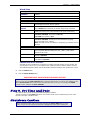
Technical Support
Country By Email By Phone
France: [email protected]
+(33) 1-64 61 09 81
Europe, Asia, Africa: [email protected]
+(44) 118 959 7774
World Headquarters
Multi-Tech Systems, Inc.
2205 Woodale Drive
Mounds View, Minnesota 55112
Phone: 763-785-3500 or 800-328-9717
Fax: 763-785-9874
Internet Address: http://www.multitech.com

Table of Contents
Multi-Tech Systems, Inc. MultiModem Wireless Modem with Ethernet Interface (S000375B) 3
Table of Contents
Chapter 1 – Introduction and Product Description.....................................................................................................5
Product and Interface Descriptions ....................................................................................................................5
Ethernet Interface............................................................................................................................................5
MultiModem EDGE..........................................................................................................................................5
MultiModem GPRS..........................................................................................................................................5
MultiModem CDMA..........................................................................................................................................5
Application Example.............................................................................................................................................6
Ship Kit Contents..................................................................................................................................................6
Safety Warnings....................................................................................................................................................7
Ethernet Ports Caution.....................................................................................................................................7
Handling Precautions.......................................................................................................................................7
Safety Instructions for Hazardous Locations....................................................................................................7
Vehicle Safety..................................................................................................................................................7
Specifications........................................................................................................................................................8
AT Command Information....................................................................................................................................8
Chapter 2 – Getting Started ..........................................................................................................................................9
Wireless Account Setup Introduction.................................................................................................................9
Step 1. Obtain a Wireless Account.....................................................................................................................9
Step 2. Connect Antenna, Ethernet, & Power..................................................................................................10
Front Panel LEDs ..........................................................................................................................................11
Ethernet LEDs ...............................................................................................................................................11
Modem LEDs.................................................................................................................................................11
Step 3. Set Your PC’s TCP/IP Address for Ethernet Functionality................................................................12
Step 4. Important Prerequisite for Activating a CDMA Account....................................................................13
Step 5. CDMA Activation Steps ........................................................................................................................14
Step 6. Using AT Commands to Verify Signal Strength and Network Registration.....................................16
Prerequisite Setup.........................................................................................................................................16
Open the Command Window.........................................................................................................................16
Verify Signal Strength....................................................................................................................................16
Checking Network Registration and Roaming Status ....................................................................................17
Step 7. Configure the Ethernet Interface Using the Web Management Software.........................................18
Step 8. Set Time and Date.................................................................................................................................19
Shutdown Caution..............................................................................................................................................19
Step 9. Connecting to the Internet....................................................................................................................20
Connecting to the Internet Through Your Cellular Provider’s Service............................................................20
Connecting to the Internet Steps ...................................................................................................................20
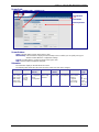
Chapter 3 – Using the Web Management Software...................................................................................................22
Navigating the Web Management Software......................................................................................................22
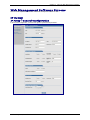
Web Management Software Screens ................................................................................................................24
IP Setup................................................................................................................................................................24
IP Setup > General Configuration..................................................................................................................24
IP Setup > HTTP Configuration .....................................................................................................................25
IP Setup > DDNS Configuration.....................................................................................................................26
IP Setup > SNTP Configuration.....................................................................................................................27
IP Setup > Static Routes................................................................................................................................28
IP Setup > Remote Configuration..................................................................................................................29
PPP.......................................................................................................................................................................30
PPP > PPP Configuration..............................................................................................................................30
PPP > Wakeup-on-Call..................................................................................................................................32
PPP > Wakeup-On-Call Examples ................................................................................................................33
PPP > Power-On Configuration.....................................................................................................................36

Table of Contents
Multi-Tech Systems, Inc. MultiModem Wireless Modem with Ethernet Interface (S000375B) 4
Networks & Services ..........................................................................................................................................37
Networks & Services > Network Configuration ..............................................................................................37
Networks & Services > Service Configuration................................................................................................38
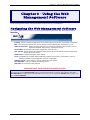
Packet Filters.......................................................................................................................................................39
Packet Filters > Packet Filters. ......................................................................................................................39
Packet Filters > DNAT Configuration.............................................................................................................40
Packet Filters > DNAT Example ....................................................................................................................40
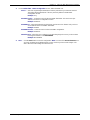
Packet Filters > Advanced.............................................................................................................................42
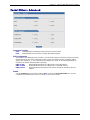
GRE Tunnels .......................................................................................................................................................43
GRE Tunnels > GRE Tunnels........................................................................................................................43
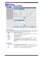
GRE Tunnels > GRE Routes Configuration...................................................................................................44
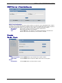
DHCP Server........................................................................................................................................................45
DHCP Server > Subnet Settings....................................................................................................................45
DHCP Server > Fixed Addresses ..................................................................................................................46
Tools ....................................................................................................................................................................46
Tools > Tools.................................................................................................................................................46
Tools > Service Status...................................................................................................................................47
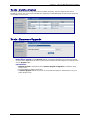
Tools > Firmware Upgrade............................................................................................................................47
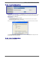
Tools > Load Configuration............................................................................................................................48
Tools > Save Configuration ...........................................................................................................................48
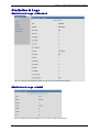
Statistics & Logs.................................................................................................................................................49
Statistics & Logs > Ethernet...........................................................................................................................49
Statistics & Logs > Serial...............................................................................................................................49
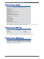
Statistics & Logs > PPP.................................................................................................................................50
Statistics & Logs > PPP Trace.......................................................................................................................51
Statistics & Logs > SysInfo............................................................................................................................52
Statistics & Logs > DHCP Stat.......................................................................................................................52
Statistics & Logs > GRE Statistics.................................................................................................................52
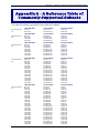
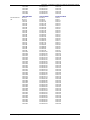
Appendix A – A Reference Table of Commonly Supported Subnets......................................................................53
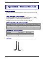
Appendix B – Wireless Antenna.................................................................................................................................55
The Antenna........................................................................................................................................................55
GSM, EDGE, and CDMA Antenna.................................................................................................................55
GSM and E-GSM Radio Characteristics........................................................................................................55
CDMA Radio Characteristics .........................................................................................................................55
Antenna .........................................................................................................................................................55
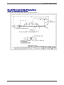
Fused DC Power Cable Dimensions .............................................................................................................56
How to Change the Fuse...............................................................................................................................56
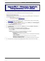
Appendix C – Firmware Upgrade Using External TFTP Client.................................................................................57
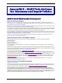
Appendix D – Multi-Tech Systems, Inc. Warranty and Repair Policies...................................................................58
Multi-Tech Warranty Statement.........................................................................................................................58
Replacement Parts ........................................................................................................................................59
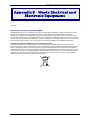
Appendix E – Waste Electrical and Electronic Equipment.......................................................................................60
Index .............................................................................................................................................................................61

Chapter 1 – Introduction and Product Description
Multi-Tech Systems, Inc. MultiModem Wireless Modem with Ethernet Interface (S000375B) 5
Chapter 1 – Introduction and
Product Description
This User Guide describes the MultiModem® Wireless EDGE, GPRS, and CDMA modems with an Ethernet
Interface.
Product and Interface Descriptions
Ethernet Interface
The MultiModem wireless modems with an Ethernet interface provide shared Internet access with one IP
address. The built-in routing capabilities provide DHCP services and firewall security using Network Address
Translation. Due to the routing capabilities, these modems are sometimes called routers.
These modems support "always-on" network connection as well as "dial-on-demand" for Internet services. The
"always-on" network connection automatically establishes a wireless data connection and allows for around the
clock surveillance, monitoring or real-time data acquisition of any remote Ethernet device such as a Web
camera. If the data link is dropped in the event of poor reception or a complete loss of service, it will
automatically re-establish the data link. When configured for "dial-on-demand" the wireless modem only
accesses the Internet when data is present. This configuration is ideal for sharing Internet access among
networked PCs.
Software features include remote configuration, firmware upgrade, load configuration screen, and a save
configuration screen.
MultiModem EDGE
The MultiModem
®
EDGE wireless modem delivers some of the fastest cellular wireless data speeds utilizing
EDGE technology. It allows users to connect to the Internet and send and receive data up to three times faster
than possible with an ordinary GSM/GPRS network making it ideal for highly data-intensive multimedia
applications. The MultiModem EDGE wireless modem is equipped with quad-band GSM, which means it can be
used worldwide on all existing GSM networks.
AT Commands: The MultiModem EDGE wireless modem is configured using the EDGE AT
Commands. These commands are documented in the Reference Guide for the MultiModem
Wireless EDGE Modems, document number S000371x.
MultiModem GPRS
The MultiModem
®
GPRS wireless modem offers standards-based multi-band GSM/GPRS Class 10
performance. The ready-to-deploy, standalone data/fax/voice modem allows developers to add wireless
communication to products with a miniumum of development time and expense. The MultiModem
®
GPRS
wireless modem is base on industry-standard open interfaces and can be desktop or panel mounted.
AT Commands: The MultiModem GPRS wireless modem is configured using the GPRS AT
Commands. These commands are documented in the Reference Guide for the MultiModem
Wireless GPRS Modems, document number S000293x and also the Reference Guide for the
GSM IP Commands, document number S000333x.
MultiModem CDMA
The MultiModem
®
CDMA wireless modem offers standards-based multi-band CDMA200 1xRTT performance.
The ready-to-deploy, standalone data/fax/voice modem allows developers to add wireless communication to
products with a miniumum of development time and expense. The MultiModem
®
CDMA wireless modem is base
on industry-standard open interfaces and can be desktop or panel mounted.
AT Commands:The MultiModem CDMA wireless modem is configured using the CDMA AT
Commands. These commands are documented in the Reference Guide for the MultiModem
Wireless CDMA Modems, document number S000294x.

Chapter 1 – Introduction and Product Description
Multi-Tech Systems, Inc. MultiModem Wireless Modem with Ethernet Interface (S000375B) 6
Application Example
Ship Kit Contents
The wireless modem is shipped with the following:
Single Unit Package
Bundled Package (multiple units)
Each individual package in the bundle includes the following:
1 modem
1 fused DC power cable
4 plastic feet for flat surface mounting
1 Quick Start Guide
1 MultiModem CD
Note: You must supply an antenna.
1 modem
1 power supply cable (varies)
4 plastic feet for flat surface mounting
1 antenna
1 Quick Start Guide
1 MultiModem CD
Note: Some ship kits may contain printed Customer Activation Notices (directions for activating your modem
through your wireless service provider).

Chapter 1 – Introduction and Product Description
Multi-Tech Systems, Inc. MultiModem Wireless Modem with Ethernet Interface (S000375B) 7
Safety Warnings
Ethernet Ports Caution
The Ethernet ports are not designed to be connected to a Public Telecommunication Network.
Handling Precautions
All devices must be handled with certain precautions to avoid damage due to the accumulation of static charge.
Although input protection circuitry has been incorporated into the devices to minimize the effect of this static build
up, proper precautions should be taken to avoid exposure to electrostatic discharge during handling and
mounting.
Caution: Maintain a separation distance of at least 20 cm (8 inches) between the
transmitter’s antenna and the body of the user or nearby persons. The modem is not
designed for, nor intended to be, used in applications within 20 cm (8 inches) of the body of
the user.
Safety Instructions for Hazardous Locations
Only GPRS and CDMA are approved for hazardous locations.
• The modems are open devices intended for installation in an ultimate enclosure suitable for the intended
application. .
• All wiring must be in accordance with wiring methods of Article 501.4B of the National Electrical Code, NFPA
70 or as specified in section 18-152 of the Canadian Electrical Code for installation within Canada and in
accordance with the authority having jurisdiction.
• “WARNING - EXPLOSION HAZARD - Substitution of Components may Impair Suitability for Class I Division
2”.
• “WARNING - EXPLOSION HAZARD - Do not Disconnect Equipment Unless Power has been switched off or
the area is known to be Non-Hazardous”.
• “WARNING - EXPLOSION HAZARD - Do not replace the Fuse Unless Power has been switched off or the
area is known to be Non-Hazardous”.
• “WARNING - Do not install or remove the SIM card Unless Power has been switched off or the area is known
to be Non-Hazardous”.
Vehicle Safety
• Do not use your Wireless MultiModem while driving, unless equipped with a correctly installed vehicle kit
allowing ‘Hands-Free’ Operation.
• Respect national regulations on the use of cellular telephones in vehicles. Road safety always comes first.
• If incorrectly installed in a vehicle, the operation of Wireless MultiModem telephone could interfere with the
correct functioning of vehicle electronics. To avoid such problems, be sure that qualified personnel have
performed the installation. Verification of the protection of vehicle electronics should be part of the installation.
• The use of an alert device to operate a vehicle’s lights or horn on public roads is not permitted.

Chapter 1 – Introduction and Product Description
Multi-Tech Systems, Inc. MultiModem Wireless Modem with Ethernet Interface (S000375B) 8
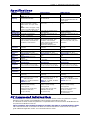
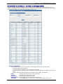
Specifications
Features EDGE Modems GPRS Modems CDMA Modems
Performance EDGE: E-GPRS Class 10,
GPRS: Class 12
GPRS Class 10 CDMA2000 1xRTT
Band,
Frequency
Quad-band GSM
850/900/1800/1900 MHz
Dual-band 850/1900 or 900/1800
MHz GSM/GPRS
Dual-band 800/1900 MHz CDMA;
800 MHz and 800/1900 MHz with
R-UIM support
Packet Data EDGE: E-GPRS Up to 240K bps,
coding scheme MCS-9, mobile
station Class B, LLC layer, 4 time
slots
GPRS: Full PBCCH support, coding
scheme 1-4, mobile station Class B
Up to 85.6K bps, coding schemes
CS1 to CS4
Up to 153.6K bps forward and
reverse
Circuit-
Switched Data
Up to 14.4K bps, non-transparent Up to 14.4K bps transparent and
non-transparent
IS-95A, IS 95B up to 14.4K bps
forward and reverse
Short Message
Services-SMS
Text & PDU, Point-to-Point
(MO/MT), cell broadcast
Text & PDU, Point-to-Point, cell
broadcast
Text & UCS-2, Point-to-Point, cell
broadcast
Fax Class 1 Group 3 GSM Class 1 and Class 2 Group 3 Class 2.0 Group 3
Voice Features Half rate (HR), Full rate (FR),
Enhanced full rate (EHR), Adaptive
multi rate (AMR), hands free echo
cancellation, noise reduction
Half rate (HR), Full rate (FR),
Enhanced full rate (EHR), echo
cancellation, noise reduction
(option), telephony and Dual Tone
Multi Frequency (DTMF)
transmission, emergency calls
Telephony and Dual Tone Multi
Frequency (DTMF) functionality,
AMPS Voice, QCELP (13K), echo
cancellation
Antenna
Connectors
RF Antenna: 50 ohm SMA (female
connector)
RF Antenna: 50 ohm SMA (female
connector)
RF Antenna: 50 ohm SMA (female
connector)
SIM Connector Standard 3V SIM receptacle Standard 3V SIM receptacle
Interface
Connectors
Ethernet Model: RJ-45,
10BaseT/100BaseTX, 802.3
Ethernet Model: RJ-45,
10BaseT/100BaseTX, 802.3
Ethernet Model: RJ-45,
10BaseT/100BaseTX, 802.3
Power
Connectors
Ethernet Model: 2.5mm miniature
screw
Ethernet Model: 2.5mm miniature
screw
Ethernet Model: 2.5mm miniature
screw
Voice
Connectors
Ethernet Model: RJ-9 4-pos
modjack
NA NA
Power
Requirements
5V to 32 VDC 5V to 32 VDC 5V to 32 VDC
Physical
Description
Ethernet Model:
2.8" L x 6.4" W x 1.2" H; 11.5 oz.
(7.1 cm x 16.3 cm x 3.0 cm; 326G)
Ethernet Model:
2.8" L x 6.4" W x 1.2" H; 11.5 oz.
(7.1 cm x 16.3 cm x 3.0 cm; 326G)
Ethernet Model:
2.8" L x 6.4" W x 1.2" H; 11.5 oz.
(7.1 cm x 16.3 cm x 3.0 cm; 326G)
Operating
Temperature
-30° to +65° C -20° to +55° C -20° to +55° C
Storage
Temperature
-40° to +85° C -40° to +85° C -40° to +85° C
Humidity Relative humidity 20% to 90%
condensing
Relative humidity 20% to 90%
condensing
Relative humidity 20% to 90%
condensing
Certifications CE Mark, R&TTE
EMC: FCC Part 2, 15, 22, 24; EN
55022, EN 55024
Safety: cUL, UL 60950; EN 60950
Network: PTCRB
CE Mark, R&TTE
EMC: FCC Part 2, 15, 22, 24; EN
55022, EN 55024
Safety: cUL, UL 60950; EN 60950
Network: PTCRB
EMC: FCC Part 2, 15, 22, 24; EN
55022, EN 55024
Safety: cUL, UL 60950; EN 60950
Network: CDG 1 & 2
Miscellaneous AT Command Compatible
Desktop or panel mounting
Carrier approved
Numerous LEDs provide status
Embedded TCP/IP stack
Two year warranty
AT Command Compatible
Desktop or panel mounting
Carrier approved
Numerous LEDs provide status
Embedded TCP/IP stack
Two year warranty
AT Command Compatible
Desktop or panel mounting
Carrier approved
Numerous LEDs provide status
Over-the-air activation
Embedded TCP/IP stack
Two year warranty
AT Command Information
AT Commands: AT commands for the GPRS, CDMA, and EDGE wireless modem are published in separate
Reference Guides included on the MultiModem CD and posted on the Multi-Tech web site.
IP commands for GPRS modems are published in a separate Reference Guide included on the MultiModem CD
and posted on the Multi-Tech web site.
SIM AT Commands: SIM commands for GPRS are included in the GPRS AT Commands Reference Guide.
SIM commands for EDGE are included in the EDGE AT Commands Reference Guide and also in a separate
guide entitled SIM Application Toolkit – AT Commands Reference Guide.

Chapter 2 – Getting Started
Multi-Tech Systems, Inc. MultiModem Wireless Modem with Ethernet Interface (S000375B) 9
Chapter 2 – Getting Started
Wireless Account Setup Introduction
Please see the wireless account Activation Notices located on the MultiModem CD. Choose the one for your
wireless network provider and follow the directions to activate your account. These directions are also included in this
chapter.
Phone Numbers for the Wireless Modem
Every wireless modem will have its own unique phone number. The phone number may simply be given to you
by your wireless service provider. For GPRS and EDGE, it may also be on the SIM card. Wireless provider
implementations may vary.
Step 1. Obtain a Wireless Account
Obtain a CDMA Account
Obtain a GSM Network Account
1. Contact your Sprint agent, Verizon agent, or
other CDMA carrier to obtain an account.
2. Provide the agent with the following:
∗ Each modem's 8-character ESN number
printed next to the barcode on the
modem.
3. You may be asked to provide the modem's
model number. This number allows the carrier
to verify this modem as one of its approved
models.
Important:
If asked for this number, give the Multi-Tech
Systems, Inc. model number located on the
modem's label. This number is not the same
as the product/device name and number.
Examples of Multi-Tech model numbers:
MTCBA-xx, MTSMC, and MTMMC
4. Your agent or wireless provider will give you
one or more of the following numbers:
∗ MDN Number – Your 10-digit phone
number.
∗ MSID Number (Some accounts call this
the MIN Number) – Another 10-digit
number.
Note: Some providers use the same
number for the MDN and the MSID.
∗ MSL Number – Your 6-digit lock code.
Also called a Service Programming
Code (SPC). Note that at this time, only
Sprint and Bell Mobility provide an MSL
number.
After you receive your numbers, be sure to record
them; they are needed in order to use your modem.
1. Contact your GSM network agent (i.e.,
Cingular).
2. Provide the agent with the following:
∗ Billing information and business ID such
as your Federal Tax I.D.
∗ The wireless services required.
∗ Each modem's 15-character IMEI
number located on the modem's label.
3. You may be asked to provide the modem's
model number. This number allows the carrier
to verify this modem as one of its approved
models.
Important: If asked for this number, give the
Multi-Tech model number located on the
modem's label. This number is not the same
as the product/device name and number.
Examples of Multi-Tech model numbers:
MTCBA-xx, MTSMC, and MTMMC.
4. Your agent will give you the following:
∗ SIM card and phone number.
5. Install the SIM Card.
Note: The wireless modem requires a SIM card
(Subscriber Identity Module) to operate on a
GSM network. It is provided by your agent.
To install the SIM card:
∗ Use a small screwdriver to remove the
screw closest to the outside edge of the
modem. Then swing the loosened SIM
slot cover up and over to the left.
∗ Insert the SIM card into the SIM card slot.
The following graphic illustrates the
correct SIM card orientation.
∗ Verify that the SIM card fits properly; then
replace the cover.

Chapter 2 – Getting Started
Multi-Tech Systems, Inc. MultiModem Wireless Modem with Ethernet Interface (S000375B) 10
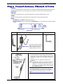
Step 2. Connect Antenna, Ethernet, & Power
Antenna
Connect a suitable antenna to SMA connector. An antenna is supplied with the bundled package ship kit. If
you purchase a single unit, you must supply your own antenna. See the User Guide for antenna/RF
specifications.
Ethernet
Using an RJ-45 Ethernet cable, connect the 10/100 jack to an internal network switch or hub.
Power
Plug one end of the power cord into the device and the other end onto a live power outlet.
Notes
• The PWR LED. The PWR LED lights after power-up.
• The Reset Button. Pressing and holding the Reset button for 5 seconds will restore all factory default
settings.
Back Panel
Antenna Power Supply Cable Ethernet Cable
This part of the power supply
cable varies by the region of the
world to which the product is
shipped: NAM / EU / GB / IE
Note: Units shipped with the universal AC power supply are not suited for installation in hazardous
locations.
Fused DC Power Connection
• Connect the direct-DC power supply cable into the DC
power source on the vehicle or machine in which you are
mounting the modem. Be sure the GND connection is
correct.
• Connect red wire to + (positive) and black wire to –
(negative).
Note: For automotive application: according to the type of
application, you can use permanent “+” or key-
switched “+”. Connect the power supply to its source
(for example, in a mobile situation, to the vehicle’s
DC fuse/terminal block).
Warning: Do not connect your wireless modem directly
to a vehicle’s battery for your power source. Doing so
may cause power spikes. If you wish to use the battery
as a power source, add a filtering device to the DC
input.

Chapter 2 – Getting Started
Multi-Tech Systems, Inc. MultiModem Wireless Modem with Ethernet Interface (S000375B) 11
Front Panel LEDs
Once the power is connected, the LEDs on the front panel will provide information about the Ethernet
functions and the wireless modem functions.
The front panel of the Ethernet EDGE has a power LED, 3 Ethernet LEDs, 5 modem LEDs, and a
SIM card slot.
The front panel of the Ethernet GPRS is the same as the Ethernet EDGE.
The front panel of the Ethernet CDMA has the same LEDs as the EDGE modem. However, it does
not have a SIM card slot.
Ethernet LEDs
IP IP FUNCTION. This LED blinks when the IP function of the modem/router is operating
normally. It shows a steady light when powering-up, initializing, or flashing the firmware.
SPD SPEED. This LED lights when the Ethernet is linked at 100 Mbps. If it is not lit, the Ethernet is
linked at 10 Mbps.
L/A LINK ACTIVITY. This LED blinks when there is transmit and receive activity on the Ethernet. It
shows a steady light when there is a valid Ethernet connection.
Modem LEDs
TD TRANSMIT DATA. This LED blinks when the modem is transmitting data to your wireless
carrier.
RD RECEIVE DATA. This LED blinks when the modem is receiving data from your wireless
carrier.
CD CARRIER DETECT. This LED lights when the modem detects a valid carrier signal from a
wireless carrier.
TR (DATA) TERMINAL READY. This LED lights when the modem is trying to establish a wireless
connection.
LS LINK STATUS.
EDGE: This LED blinks when there is network activity between the carrier and the cellular
module. At all other times, the light will be off.
GPRS & CDMA:
Continuous “on” state indicates that the wireless modem is not registered on the network.
Flashing state indicates registration on network.
Off state. Modem is off (not ready) or in download mode.

Chapter 2 – Getting Started
Multi-Tech Systems, Inc. MultiModem Wireless Modem with Ethernet Interface (S000375B) 12
Step 3. Set Your PC’s TCP/IP Address for
Ethernet Functionality
Once the wireless account is established and the modem is properly connected, it is now time to set up the PC
for the Ethernet functionality. First, you will have to set the TCP/IP address on your PC, if not previously set.
1. Open the PC's Control Panel.
2. Select Networks or Network Connections.
3. Under Protocols, select TCP/IP.
4. Under Properties, choose one of the following:
∗ Check Obtain IP Address Automatically and Obtain DNS Server Address Automatically. If
you check these, then the DHCP function obtains the IP Address automatically from the Ethernet
wireless modem, or
∗ Check Use the Following IP Address and Use the Following DNS Server Address. If you
check these, then enter the following addresses:
IP Address: 192.168.2.2
Subnet Mask: 255.255.255.0
Gateway: 192.168.2.1
Specify a DNS Server. For example, 205.171.3.65
Next Steps
CDMA
For CDMA devices, go to Step 4. Complete Steps 4 through 9.
GPRS/EDGE
For GPRS/EDGE devices, go to Step 6. Complete Steps 6 through 9.

Chapter 2 – Getting Started
Multi-Tech Systems, Inc. MultiModem Wireless Modem with Ethernet Interface (S000375B) 13
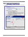
Step 4. Important Prerequisite for
Activating a CDMA Account
If you are setting up you device for the GSM network (GPRS and EDGE devices), you can skip Steps 4 and 5,
and go to Step 6.
You must disable PPP Authentication in the Web Management Ethernet software:
1. Open a Web Browser
From the workstation, open a Web Browser.
2. Type the default Gateway Address: http://192.168.2.1
3. Login
After entering the Address, the Login screen displays.
• Type the default User name: admin (all lower-case).
• Type the default password: admin (all lower-case).
Note: The User name and Password are case-sensitive (both must be typed in lower-
case). If Windows displays the AutoComplete screen, you may want to click No to tell
the Windows OS not to remember the password; this helps maintain PC security.
• Click the Login button. The Web Management Home screen displays.
4. Then select the Wizard Setup from under the Menu bar.
5. On the Wizard Setup screen under the PPP Configuration section, disable PPP.
6. Click the Submit button.
7. In order for your settings to take effect, you must click the Save & Restart button located on the
Menu bar. Your PC will shut down and reboot.

Chapter 2 – Getting Started
Multi-Tech Systems, Inc. MultiModem Wireless Modem with Ethernet Interface (S000375B) 14
Step 5. CDMA Activation Steps
Note: The following steps are for CDMA devices only. GPRS and EDGE devices were activated once the SIM card
was inserted.
Please see the wireless account Customer Activation Notices located on the MultiModem CD. Choose the one
for your wireless network provider and follow the directions to activate your account. Also, for your convenience,
the Customer Activation steps are included in the tables below.
Steps 1 through 6 take you to the screen on which to enter the Customer Activation AT commands.
1. From the workstation, open the command window by clicking the Start button and selecting Run.
2. Type CMD to open the command window. Click OK.
3. When the command window opens, type Telnet 192.168.2.1 5000
Note: 5000 is the port number.
4. At Login, enter the user name admin.
5. At Password, enter the password admin. Once logged in, you can use AT commands to communicate
with the cellular module.
6. Activate your CDMA modem by entering the following AT commands:
Step AT Command
Modem
Response
Comment
1
AT+WSPC=1,xxxxxx<cr>
OK
"xxxxxx" is your lock code (the MSL) provided by
Sprint and Bell Mobility.
Verizon and all other carriers use “000000” (6 zeros) in
place of "xxxxxx"
2
AT+WMDN=nnnnnnnnnn<cr> OK "nnnnnnnnnn" is your phone number (your MDN).
3
AT+WCMT=1<cr> OK Commits the changes to memory and locks the device.
If your MDN and MSID are identical, then you can skip steps 4, 5, and 6.
Wait 10 seconds before issuing the next command.
4
AT+WSPC=1,xxxxxx<cr> OK "xxxxxx" is your lock code (the MSL). See Step 1.
5
AT+WIMI=31000sssssssss<cr> OK "ssssssssss" is your MSID.
Alltel uses “31127” in place of “31000”
6
AT+WCMT=1<cr> OK Commits the changes to memory and locks the device.
Sprint – Add These Final Steps for Sprint Activation Only
Wait 10 seconds before issuing the next command.
Step AT Command Response Comment
7
AT+WIOTA=4 <cr>
OK Clears previous IOTA attempts.
8
AT+WIOTA=1<cr> ;+WOAP:
"Preparing Data Services"
OK
Initiates over the air activation.
Note: You must have network reception for this step.
This process requires about 3 minutes to complete.
Sprint Notes:
Modem Response – When complete, the modem will respond with +WOAR:"Please Retry." This modem
response indicates that you should retry, but you do not need to do so. Your modem should now be ready
for use.
What to Do If You Do Not Receive the "Please Retry" Response – If you do not receive the "Please
Retry" response, turn the power off and then on. Repeat Steps 7 and 8.
Verizon – Add This Final Step for Verizon Activation Only
Wait 10 seconds before issuing the next command.
Step AT Command Response Comment
7
ATD*22899; <cr> +WOT1: “Programming in Process”
+WOTS: “SPL unlocked”
+WOTP: “PRL download OK”
+WOTM: “MDM download OK”
+WOTC: “Commit successful”
+WOT2: “Programming successful”
Perform ove
r
-the-air provisioning.

Chapter 2 – Getting Started
Multi-Tech Systems, Inc. MultiModem Wireless Modem with Ethernet Interface (S000375B) 15
7. Logout After Entering Activation Commands.
a. After the last command is entered, press CTRL + ] (the right bracket).
b. This prompt displays: telnet>
Type quit and press Enter.
c. This prompt displays: c:>
Type exit and press Enter.

Chapter 2 – Getting Started
Multi-Tech Systems, Inc. MultiModem Wireless Modem with Ethernet Interface (S000375B) 16
Step 6. Using AT Commands to Verify Signal
Strength and Network Registration
Important Note: Before you can use these commands, you must complete the previous steps in this chapter.
Prerequisite Setup
In order to communicate directly with the internal cellular module with AT commands, you first must disable PPP
by logging into the Web Management software of the router:
1. From the workstation, open a Web browser.
2. Type the default Gateway Address: http://192.168.2.1
3. Login
After entering the Address, the Login screen displays.
• Type the default User name: admin (all lower-case).
• Type the default password: admin (all lower-case).
Note: The User name and Password are case-sensitive (both must be typed in lower-case). If
Windows displays the AutoComplete screen, you may want to click No to tell the Windows OS not
to remember the password; this helps maintain PC security.
• Click the Login button. The Web Management Home screen displays.
4. Select Wizard Setup.
5. On the Wizard Setup screen under PPP Configuration, disable PPP.
6. Click the Submit button.
7. Click Save & Restart.
Open the Command Window
1. From the workstation, open the command window by clicking the Start button and selecting Run.
2. Type CMD to open the command window. Click OK.
3. When the command window opens, type Telnet 192.168.2.1 5000
Note: 5000 is the port number.
3. At Login, enter the user name admin.
4. At Password, enter the password admin. Once logged in, you can use AT commands to
communicate with the cellular module.
Verify Signal Strength
1. In the command window, type AT+CSQ
2. The modem responds with the received signal strength (rssi) and the channel bit error rate (ber).
RSSI ranges from 0 to 31. BER ranges from 0 to 7 (7 is the highest error rate).
Signal Strength – RSSI
10 - 31 Sufficient
0 - 9 Weak or Insufficient
99 Insufficient
Note: Sprint models will respond differently. Please refer to the CDMA AT Command Reference Guide.

Chapter 2 – Getting Started
Multi-Tech Systems, Inc. MultiModem Wireless Modem with Ethernet Interface (S000375B) 17
Checking Network Registration and Roaming Status
Use this command to verify that the wireless MultiModem has been registered on a wireless network.
1. In the command window, type AT+CREG?
2. The modem will respond in one of the following ways:
Network Registration Verification
Value Network Registration Status
+CREG: 0,0 The modem is not registered on any network
+CREG: 0,1 The modem is registered on the home network
+CREG: 0,5 The modem is registered on a network and it is roaming
Note: If the modem indicates that it is not registered, verify the signal strength to determine if the
problem is the strength of the received signal.

Chapter 2 – Getting Started
Multi-Tech Systems, Inc. MultiModem Wireless Modem with Ethernet Interface (S000375B) 18
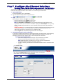
Step 7. Configure the Ethernet Interface
Using the Web Management Software
You are now ready to configure the Ethernet interface. This is accomplished by using the modem's factory-
installed Web Management software. The software is accessed through a Web browser.
1. Open a Web browser
From the workstation, open a Web browser.
2. Type the default Gateway Address: http://192.168.2.1
3. Login
After entering the Address, the Login screen displays.
• Type the default User name: admin (all lower-case).
• Type the default password: admin (all lower-case).
Note: The User name and Password are case-sensitive (both must be typed in lower-case).
A password can be up to 12 characters. If Windows displays the AutoComplete screen, you may
want to click No to tell the Windows OS not to remember the password; this helps maintain PC
security.
Password Caution: It is recommended that you change the default password to better protect the
security of your modem. Use a safe password! Your first name spelled backwards is not a
sufficiently safe password; a password such as xfT35$4 is better.
• Click the Login button. The Web Management Home screen displays.
4. Use the Wizard Setup for Quick Configuration
A quick way to configure the modem is to use the Wizard Setup. The Wizard Setup can be opened by
clicking the words Wizard Setup located under the Web Management software’s menu bar. The
information entered here will default to other screens that require this information.
Benefits of Using the Wizard Setup
• Saves time so that you are not entering the same information several times.
• Allows you to start using your device with a minimum configuration.
Note: Additional features and functions can be set up using the complete Web
Management software program, described in Chapter 3.
• Provides a short way to enter and save information needed to create a connection to the
Internet.
Select Wizard Setup
After clicking the Wizard Setup selection, the Wizards Setup screen displays.
See the tables on the next page for setup information.

Chapter 2 – Getting Started
Multi-Tech Systems, Inc. MultiModem Wireless Modem with Ethernet Interface (S000375B) 19
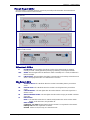
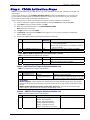
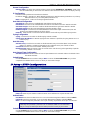
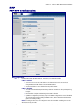
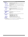
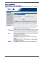
Wizard Setup
IP Configuration
IP Address
The default is 192.168.2.1. To change it, simply enter your own IP
address.
Mask
The default is 255.255.255.0
DNS
Enter the primary DNS IP address for the system. The default is 0.0.0.0
PPP Configuration
PPP
Click Enable to activate PPP. You will want to enable the PPP
functionality for the PPP dialer to operate.
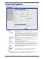
Dial-on-
Demand
Click Enable to activate dial-on-demand feature.
If you Disable dial-on-demand, the modem always stays connected.
Idle Time Out
Sets the amount of time the PPP link stays active before disconnecting.
Setting the value to zero causes the link to stay active continuously.
Dial Number
Enter the dial number. This number connects you to the Internet.
For GPRS and EDGE, the number is *99***1#.
For CDMA, the number is #777
Init String
You can set up to 5 modem initialization strings.
For GPRS and EDGE: Include the Access Point Name by typing:
AT+CGDCONT=1,"IP","<APN>"
Note: The APN (Access Point Name) is assigned by your wireless service
provider.
PPP Authentication
Authentication Type
Click the button corresponding to the authentication protocol you want to
use to negotiate with the remote peer. PAP, CHAP, or PAP-CHAP.
Default = PAP-CHAP
User Name
Enter the PPP User Name. This name authenticates the remote peer. The
default is ipmodule.
Password
Enter the PPP Password. This password authenticates the remote peer.
The default is ipmodule.
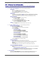
A Note About the Access Point Name
The APN (Access Point Name) is assigned by your GPRS or EDGE wireless service provider, but
you may have to ask for it. An access point is an IP network to which a wireless modem connects.
The Web Management software asks for the APN on the Wizard Setup screen and the PPP screen.
5. Click the Submit button.
6. Click the Save & Restart button.
IMPORTANT NOTE ABOUT SUBMIT AND SAVE & RESTART
Click the Submit button located at the bottom of most screens in order to save any changes you make.
Then you must click the Save & Restart button, located on the Menu bar, in order for your settings to take
effect. Save & Restart does not have to be executed after each screen; you can change and Submit
several screens, and then click Save & Restart.
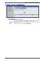
Step 8. Set Time and Date
The date and time must be set using the Web Management software.
The time and date set in IP Setup will not be correct unless SNTP client is enabled and you have a live
Internet connection. See SNTP client.
Shutdown Caution
Never unplug the power until you have first performed the Save & Reset process. If the
setup changes are not properly saved before unplugging the power, data could be lost.

Chapter 2 – Getting Started
Multi-Tech Systems, Inc. MultiModem Wireless Modem with Ethernet Interface (S000375B) 20
Step 9. Connecting to the Internet
Connecting to the Internet Through Your Cellular
Provider’s Service
This section provides step-by-step instructions for connecting to the Internet, which must be accessed through
your cellular provider.
This step includes parts of some of the previous steps; they are repeated here to show you the entire process for
connecting to the Internet.
Important Note About Provider Fees:
Your provider will charge you for your data usage. Please check with your provider to make sure you are aware
of the charges.
If you plan to use the router for large amounts of data transfers, Multi-Tech recommends an unlimited data plan
with your account. Multi-Tech will not be responsible for any charges relating to your cellular bill.
Connecting to the Internet Steps
1. Turn on your PC and login. Make sure your LAN connection is set to Obtain an IP Address
Automatically.
2. Connect the Multi-Tech router at the 10/100 port and the PC to a hub or switch using the Ethernet RJ-
45 cable. Turn on the MTCBA-x-EN by plugging in the power cable. Make sure your antenna is
connected.
For GPRS and EDGE models, make sure your SIM card is inserted correctly.
3. From the workstation, open the command window by clicking the Start button and selecting Run.
4. Type CMD to open the command window. Click OK.
5. When the command window opens, type IPCONFIG.
6. Check to make sure your LAN connection has received an IP address in the 192.168.2.x subnet from
the router. If not, type IPCONFIG /RELEASE, and then type IPCONFIG /RENEW to see if you receive
an IP address. Close the command window.
7. Open a Web browser and complete the following:
• In the Address bar type http://192.168.2.1
This opens the Web Management software included with your wireless product.
• Click Go. A Login screen displays.
• Type the following:
For Username: admin
For Password: admin
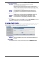
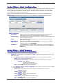
8. Once you are logged in, select PPP from the Menu bar. The PPP screen displays. The following
settings will be configured into the PPP dialer:
PPP: Enable
Dial-on-Demand: Select Disable (select disable to stay connected at all times).
Idle time out: 0 (zero indicates that the connection will not disconnect)
Username: You can keep the default (ipmodule) unless your wireless account requires
your own user name.
Password: You can keep the default (ipmodule) unless your wireless account requires
your own individual password.
Baud Rate: For CDMA and GPRS models, select
115200.
For EDGE models, select 230400.
Dial Number: For CDMA models, type #777
For GPRS and EDGE models, type *99***1#.
Init String 1: For GPRS and EDGE models, type AT+CGDCONT=1,"IP","<APN>"
Note: The APN (Access Point Name) is assigned by your wireless service
provider. APN is the name of an access point for GPRS. An access point is an
IP network to which a mobile can be connected.
Submit: Click the SUBMIT button.
9. Click Save & Restart (located on the Menu bar). The PC will shut down and reboot.
10. After your router has restarted and the IP LED is flashing, wait for about 1 minute to be sure that the TR
and CD LEDs are lit and showing a solid light (not blinking).
Page is loading ...
Page is loading ...
Page is loading ...
Page is loading ...
Page is loading ...
Page is loading ...
Page is loading ...
Page is loading ...
Page is loading ...
Page is loading ...
Page is loading ...
Page is loading ...
Page is loading ...
Page is loading ...
Page is loading ...
Page is loading ...
Page is loading ...
Page is loading ...
Page is loading ...
Page is loading ...
Page is loading ...
Page is loading ...
Page is loading ...
Page is loading ...
Page is loading ...
Page is loading ...
Page is loading ...
Page is loading ...
Page is loading ...
Page is loading ...
Page is loading ...
Page is loading ...
Page is loading ...
Page is loading ...
Page is loading ...
Page is loading ...
Page is loading ...
Page is loading ...
Page is loading ...
Page is loading ...
Page is loading ...
Page is loading ...
-
 1
1
-
 2
2
-
 3
3
-
 4
4
-
 5
5
-
 6
6
-
 7
7
-
 8
8
-
 9
9
-
 10
10
-
 11
11
-
 12
12
-
 13
13
-
 14
14
-
 15
15
-
 16
16
-
 17
17
-
 18
18
-
 19
19
-
 20
20
-
 21
21
-
 22
22
-
 23
23
-
 24
24
-
 25
25
-
 26
26
-
 27
27
-
 28
28
-
 29
29
-
 30
30
-
 31
31
-
 32
32
-
 33
33
-
 34
34
-
 35
35
-
 36
36
-
 37
37
-
 38
38
-
 39
39
-
 40
40
-
 41
41
-
 42
42
-
 43
43
-
 44
44
-
 45
45
-
 46
46
-
 47
47
-
 48
48
-
 49
49
-
 50
50
-
 51
51
-
 52
52
-
 53
53
-
 54
54
-
 55
55
-
 56
56
-
 57
57
-
 58
58
-
 59
59
-
 60
60
-
 61
61
-
 62
62


Multi-Tech Systems Multimodem RJ-9 User manual
- Category
- Networking
- Type
- User manual
Ask a question and I''ll find the answer in the document
Finding information in a document is now easier with AI
Related papers
-
Multi-Tech Systems MTCBA-E-EN User manual
-
Multitech GPRS User manual
-
-
-
-
-
-
-
-
Multi-Tech Systems MTZPC-C User manual
Other documents
-
 Multi Tech Equipment GPRS USB User manual
-
Hypercom M4230 User manual
-
-
Multitech SF100-G Specification
-
Sagem 2864 Owner's manual
-
Multi-Tech SocketModem EDGE Reference guide
-
Mikster Logginet UNI Owner's manual
-
-
Multi-Tech MultiModem ZBA MT9234ZBA Quick start guide
-
Multitech MultiModem ZBA MT9234ZBA Quick start guide
