Page is loading ...

24VAC Interface Option Card
G+Mini 24VAC IF CARD
144-25075
January 2009 Page 1 of 2
Part Number: 144-25078 (G+M 24VAC IF CARD)
Applicability: G+ Mini
Introduction: The G+M 24VAC Interface option card mounts directly to the control board
terminals (S1 – S7 and SC) on the drive. This card allows 24 VAC control logic circuits to
interface with the seven digital inputs (S1 – S7) with the G+ Mini control circuitry.
Receiving: All equipment is tested against defect at the factory. Report any damages, shortages
evident when the equipment is received to the commercial carrier who transported the equipment.
Warning: Hazardous voltage can cause severe injury or death. Lock all power sources feeding
the drive and the option card’s wiring in the “OFF” position.
Important: When handling boards always use electrostatic discharge (ESD) protection. Keep the
boards in the ESD bag as long as you can. Do not lay the board on any surfaces without ESD
protection. When handling, always hold the board from the edges and do not touch the
components. Before installing this option card, a technically qualified individual, who is familiar
with this type of equipment and the hazards involved, should read this entire installation guide.
Control Circuit Terminals:
The G+ M 24V IF CARD has seven optically isolated input terminals which can be used to
connect with the user 24 VAC devices. The interface card connects to drive terminals S1-S7 and
SC. The users 24 VAC input devices will then connect to terminals S1-S7 and X2 on the interface
card. Terminals S1 and S2 are factory set for the forward (up) and reverse (down) run
commands; however, they can be programmed for speed control and other functions like the
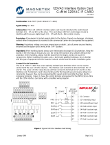
remaining terminals. Figure 1 shows the control terminal arrangement for the IMPULSE•G+ Mini
with the 24V interface card along with a simplified wiring diagram.
Fi
g
ure 1. T
yp
ical 24 VAC Interface Car
d
Wirin
g
24 VAC
INTERFACE
CARD
24 VAC
X2
S1
S2
S3
S4
S5
S6
S7
SC Common
S1 Forward/Up Input
S2 Reverse/Down Input
S3 Multi-function Input
S4 Multi-Function Input
S5 Multi-Function Input
S6 Multi-Function Input
S7 Multi-Function Input
FWD
REV
Spd 2
Spd 3
Spd 4
Spd 5
UL2
LL2
X2X1

24VAC Interface Option Card
G+Mini 24VAC IF CARD
144-25075
January 2009 Page 2 of 2
Installation and Wiring:
Use the following steps, along with Tables 1 and 2 to in install the G+M 24V IF.
Table 1. Terminal and Wire Specifications
(G+ Mini 24 VAC Interface Card and Control Board)
Terminals
Symbol
Terminal
Screw
Tightening Torque
(in-lbs)
Control Wiring
(AWG)
Recommended
(AWG)
S1-S7, SC M2 1.1 to 2.2 24 to 16 18/16
Important: Wires to the option card should be stripped 0.2” ±20% for maximum system safety.
Ferrules are also recommended.
Table 2. Terminal Functions
Classification Terminal Signal Function Description Signal Level
S1 Forward run/stop*
Forward run when closed,
stop when open. (H01.01)
S2 Reverse run/stop*
Reverse run when closed,
stop when open. (H01.02)
S3 Multi-function Input*
S4 Multi-function Input*
S5 Multi-function Input*
S6 Multi-function Input*
S7 Multi-function Input*
Multi-function contact inputs
(H01.03 to H01.07)
Sequence Input
Signal
X2 Common Control Input Common
24 VAC ± 10%
*Parameter functions and defaults change based on X-Press programming.
1. Disconnect all electrical power to the drive.
2. Remove the front cover for the drive. (Depending on
model, you may need to remove the protective cover
and discard – See Figure 2).
3. Verify that the “CHARGE” indicator lamp inside the
drive is off (It may take as long as 10 minutes for the
charge on the DC bus capacitors to drop to a safe
level).
4. Use a voltmeter to verify that the voltage at the
incoming power terminals (R/L1, S/L2, and T/L3) has
been disconnected.
5. Loosen the terminals S1 – S7 and SC on the drive
controller board.
6. Remove the G+ M 24V IF CARD from the ESD bag.
7. Connect your 24VAC interface devices to terminals S1-
S7, X2 on the G+M 24V IF CARD. (See Figure 1 and
Table 2).
8. Insert the G+M 24 VAC IF CARD into terminals S1-S7
and SC.
9. Tighten the terminals.
10. Reinstall the front cover.
Figure 2. Protective Cover
/


