Page is loading ...

POP NUT™
Tool
PNT800A
Maintenance Manual

Page 2 Emhart Teknologies - 50 Shelton Technology Center, Shelton CT 06484 - Tel. (203) 924-9341 - Fax (800) 225-5614
Page intentionally blank

Emhart Teknologies - 50 Shelton Technology Center, Shelton CT 06484 - Tel. (203) 924-9341 - Fax (800) 225-5614 Page 3
Contents
Safety Instructions....................................................................................................................................4
Tool Parts .................................................................................................................................................5
Packaged Accessories..........................................................................................................................5
Introduction...............................................................................................................................................6
Specifications ...........................................................................................................................................8
Tool Set Up...............................................................................................................................................9
Stroke Adjustment ..................................................................................................................................10
Operation................................................................................................................................................12
PNT800A Diagram .................................................................................................................................16
Parts List ................................................................................................................................................18
Maintenance and Testing........................................................................................................................20
Troubleshooting......................................................................................................................................26

Page 4 Emhart Teknologies - 50 Shelton Technology Center, Shelton CT 06484 - Tel. (203) 924-9341 - Fax (800) 225-5614
Safety Instructions
TO INSURE PROPER FUNCTIONING AND SAFE OPERATION READ THIS MANUAL
CAREFULLY BEFORE SETTING UP OR OPERATING THE POP NUT SERIES TOOLS
DEFINITIONS:
• CAUTION! – Failure to observe this precaution could result in physical damage or
minor injury.
• WARNING! – Failure to observe this precaution could result in physical damage,
serious injury or even death.
CAUTION!
1. DO NOT use this tool in a manner other than that recommended by Emhart Teknologies.
2. DO NOT modify the tool in any way. Modification will void any applicable warranties and
could result in damage to the tool or physical injury to the user.
3. Disconnect air supply when adjusting, servicing or removing any part of the tool.
4. Trained personnel must perform tool repair and/or maintenance at prescribed intervals.
5. Only use genuine Emhart Teknologies parts for tool maintenance and repair.
6. Do not operate the tool with the Nose Housing removed.
7. Keep fingers away from the front of the tool when connecting the air supply or using the
tool.
8. Do not attempt to turn the Mandrel when the air supply is connected.
9. Keep hair, fingers and loose clothing away from moving parts of the tool.
10. Do not direct tool exhaust towards anyone. The tool uses lubricated air and may eject oil
mist or debris.
11. Do not use organic solvents to clean the tool, this can damage the tool.
12. Wash hands thoroughly if exposed to hydraulic fluid or lubricant.
WARNING!
1. DO NOT exceed the maximum recommended air pressure of 0.6 MPa (87 psi / 6.0 bar).
2. DO NOT point the tool at anyone when in use.
3. Always wear safety rated eye protection when using or when near a tool in use.
4. Inspect the tool and connections for damage, worn or loose parts before connecting to the
air supply. If damaged, stop use immediately and have the tool repaired or replaced.
5. This tool is not designed for use in explosive atmospheres.

Emhart Teknologies - 50 Shelton Technology Center, Shelton CT 06484 - Tel. (203) 924-9341 - Fax (800) 225-5614 Page 5
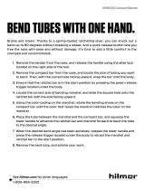
Tool Parts
Packaged Accessories
Part No. Item Qty
PNT800A-T PNT800A POP NUT Tool 1
PNT600-132 Hook 1
PNT600-133 Hex wrench 1.5 mm 1
DPN907-006 Cap screw M4 X 20 1
DPN277-179 POP NUT Mandrel Release 1
FG2245 Operating Instructions 1
FG2244 Maintenance Manual 1
FG2222 Warranty Card 1
Air Chamber
Lock nut
Stroke Control
knob
Swivel fitting
(NPT 1/4)
Front case
Rear case
Mandrel
Nosepiece / Anvil
Nose Housing
Trigger
Handle
Fill screw
Coupler
(Plug)
Not included
Hose
Coupler
(Socket)
Exhaust holes
Exhaust holes

Page 6 Emhart Teknologies - 50 Shelton Technology Center, Shelton CT 06484 - Tel. (203) 924-9341 - Fax (800) 225-5614
Introduction
The PNT800A is a small, lightweight tool for installing POP® brand POP NUT™ blind rivet nuts and
other blind threaded inserts. It is driven by compressed air.
Table 2-1 lists the POP NUT blind rivet nuts that can be fastened using this tool. The Nosepiece
and Mandrel must be changed to fit some sizes of POP Nut. (See table 2-2)
Table 2-1 Tool capacity
Thread Size
M3 M4 M5 M6 M8 M10
POP NUT Type Material
6-32 8-32 10-24 /
10-32 1/4-20 5/16-18 3/8-16
Steel 3 3 3 3 3 3
Aluminum 3 3 3 3 3 3
Standard nut
Stainless 3 3 3 3 3
Steel 3 3 3 3 3 3
Aluminum 3 3 3 3 3 3
Closed End nut
Stainless 3 3 3 3 3
Steel 3 3 3 3 3
Hexgonal nut Aluminum 3 3 3 3
Square nut Steel 3 3 3 3
Knurled nut Steel 3 3 3 3
Table 2-2
Flat Nosepiece Mandrel
Thick Wall
POP NUT
Thread
size
POP NUT Tool
Part No.
Part No. I.D. Part No.
Thread
size
M3×0.5 PNT800A-3 PNT600-02-3 Φ 4.0 PNT600-01-3 M3×0.5
M4×0.7 PNT800A-4 PNT600-02-4 Φ 4.5 PNT600-01-4 M4×0.7
M5×0.8 PNT800A-5 PNT600-02-5 Φ 5.1 PNT600-01-5P M5×0.8
M6×1.0 PNT800A-6 PNT600-02-6 Φ 6.1 PNT600-01-6P M6×1.0
M8×1.25 PNT800A-8 PNT600-02-8 Φ 8.1 PNT600-01-8 M8×1.25
M10×1.5 PNT800A-10 PNT600-02-10 Φ 10.1 PNT600-01-10A M10×1.5
M4,M5,M6
set PNT800A
I.D. Thread size M8×1.0

Emhart Teknologies - 50 Shelton Technology Center, Shelton CT 06484 - Tel. (203) 924-9341 - Fax (800) 225-5614 Page 7
Flat Nosepiece Mandrel
Thick Wall
ST
POP NUT
Thread
size
POP NUT Tool
Part No.
Part No. I.D. Part No.
Thread
size
6 – 32 PNT800A-632R PNT600-02-632 Φ 3.6 PNT600-01-632 6 – 32
8 – 32 PNT800A-832R PNT600-02-832 Φ 4.3 PNT600-01-832 8 – 32
10 – 24 PNT800A-1024R PNT600-02-5 Φ 5.1 PNT600-01-1024 10 – 24
10 – 24 PNT800A-1032R PNT600-02-5 Φ 5.1 PNT600-01-1032 10 – 32
¼ - 20 PNT800A-420R PNT600-02-420 Φ 6.5 PNT600-01-420 ¼ - 20
5/16 – 18 PNT800A-518R PNT600-02-8 Φ 8.1 PNT600-01-518R 5/16 – 18
3/8 – 16 PNT800A-616R PNT600-02-10 Φ 10.1 PNT600-01-616R 3/8 – 16
Piloted Nosepiece Mandrel
Thin Wall
TK, TL &
TH
POP NUT
Thread
size
POP NUT Tool
Part No.
Part No. I.D. Part No.
Thread
size
6 – 32 PNT800A-632P PNT600-02-3P Φ 3.6 PNT600-01-632 6 – 32
8 – 32 PNT800A-832P PNT600-02-4P Φ 4.3 PNT600-01-832 8 – 32
10 – 24 PNT800A-1024P PNT600-02-5P Φ 5.1 PNT600-01-1024 10 – 24
10 – 24 PNT800A-1032P PNT600-02-5P Φ 5.1 PNT600-01-1032 10 – 32
¼ - 20 PNT800A-420P PNT600-02-420P Φ 6.5 PNT600-01-420 ¼ - 20
5/16 – 18 PNT800A-518P PNT600-02-8P Φ 8.1 PNT600-01-518 5/16 – 18
3/8 – 16 PNT800A-616P PNT600-02-10P Φ 10.1 PNT600-01-616 3/8 – 16
M4×0.7 PNT800A-4P PNT600-02-4P Φ 4.3 PNT600-01-4P M4×0.7
M5×0.8 PNT800A-5P PNT600-02-5P Φ 5.1 PNT600-01-5P M5×0.8
M6×1.0 PNT800A-6P PNT600-02-6P Φ 6.1 PNT600-01-6P M6×1.0
M8×1.25 PNT800A-8P PNT600-02-8P Φ 8.1 PNT600-01-8P M8×1.25
M10×1.5 PNT800A-10P PNT600-02-10P Φ 10.1 PNT600-01-10P M10×1.5
* Refer to the Maintenance and Testing section for details of Nosepiece and Mandrel replacement.
I.D. Thread size M8×1.0
I.D. Thread size M8×1.0

Page 8 Emhart Teknologies - 50 Shelton Technology Center, Shelton CT 06484 - Tel. (203) 924-9341 - Fax (800) 225-5614
Specifications
Table 3-1
Hydraulic oil
Use only Emhart Teknologies specified hydraulic oils as shown in Tabel 3-2.
Use of any other oil could reduce the tool performace or even damage the tool..
Table 3-2 Specified hydraulic oils
Company name Product name
Mobile Mobile DTE26
Shell Shell Telus Oil C68
Idemitsu Daphne Hydro 68A
Cosmo Cosmo Olpas 68
Esso Telesso 68
Nisseki FBK RO68
Mitsubishi Diamond Lube RO68 (N)
Feature Specification
Weight 1.68 kg (3.7 lbs)
Overall length 288 mm (11.3 in)
Overall height 263 mm (10.4 in)
Tool Stroke 1.3 - 6.3 mm (0.05 - 0.248 in)
Pulling Force 23.4 kN @ 5.0 bar ( 5260 lbf @ 72.5 psi)
Compressed air pressure required 0.5 - 0.6MPa (5 - 6 bar)
(72.5 - 87 psi)
Hydraulic Oil See Table 3-2 Specified Hydraulic Oils
Setting capacity See table 2-2
Tool Noise Level 72.7 dB(A)
Tool Vibration Level 0.92 m/s2 / 2.5 m/s2 > 24hrs (EAV)
Figure 3-1

Emhart Teknologies - 50 Shelton Technology Center, Shelton CT 06484 - Tel. (203) 924-9341 - Fax (800) 225-5614 Page 9
Tool Set Up
1. Check that the correct Nosepiece and Mandrel are fitted for the POP Nut.
Adjust the protruding length of the Mandrel. (Refer to “Maintenance and Testing”
section B).
2. The thread type of the compressed air supply coupling is NPT 1/4.
Connect a joint or coupler of thread type NPT 1/4 to supply compressed air.
(The Coupler and Joint are not provided.)
3. An air filter, regulator and lubricator should be fitted in the air line between the
compressor and the tool, within 3m (6 ft) of the tool. Adjust the supply pressure and
the drip volume of the lubricator oil.
• Compressed air pressure: 0.5-0.6 MPa. (72.5-87 psi)
• Oil drip volume from the lubricator: 1-2 drops/ 20 nuts fastened
WARNING!
Use an air hose with a rating of 1.0 MPa (145 psi / 10 bar) or greater maximum ordinary
operating pressure. Also make sure the hose material is suitable for the operating
environment (i.e. oil proof, wear and abrasion resistance etc.).
*For details, refer to a hose manufacturer's catalog.
Coupler (Plug)
Thread size NPT 1/4
Regulator
I.D. 6.5mm
(
1/4”
)
Min.
Not attached
Hose
Compressor
Air filter
Lubricator
Figure 4-1
Cou
p
le
r
(
Socket
)
3m
(
6ft
)
Max.

Page 10 Emhart Teknologies - 50 Shelton Technology Center, Shelton CT 06484 - Tel. (203) 924-9341 - Fax (800) 225-5614
Figure 4-3
Figure 5-1
Work piece thickness
Maximum stroke (SMax )
Lock screw
(Never Loosen)
Lock screw
(Use 1.5mm hex)
Edge of control nut
Scale Control knob
Control nut
Figure 5-2
Stroke Adjustment
• Adjust the stroke length according to POP Nut size and the thickness of work piece.
• Make sure the tool has a consistent and adequate air supply.
• Note: The stoke may increase or decrease due to changes in air pressure [~0.1 mm (0.004
in) per 0.1 MPa (15 psi)]
PROCEDURE
1. Determine required stroke
Find Maximum Stroke (S max), Minimum Stroke (S min)
and Stroke (E), based on the POP Nut and work piece
thickness from Table 5-5 "POP Nut Stroke Formulas”
and Table 5-6 “S max vs. t Graph.”
Example:
POP Nut: SPH625
Work piece thickness: 1.5mm
S max = 3.4 from formula or graph
S min = 3.0 (S max − 0.4.) from formula
E = 3.6 (S max + 0.2) from formula
Proper stroke: 3.0 ~ 3.4 (S min ~ S max)
2. Stroke Adjustment
a) Loosen the M3 lock screw on the control
nut using a 1.5mm hexagonal wrench. Adjust
stroke by turning control knob clockwise to
decrease and anti-clockwise to increase stroke.
Stroke, E is indicated by the right edge of
control nut. Tighten the lock screw (Figure 5-2).
Note: Never loosen the lock screw on the
control knob, as this will disturb the stroke.
b) Set a POP Nut and measure the stroke
with calipers etc. to check the stroke setting
‘E’.
Re-adjust the stroke according to (a) so that
the stroke is E ± 0.1mm. (Figure 5-3).
Note: Using the control knob, adjustments equal to
0.2mm per quarter turn can be made.
c) Set a POP Nut using work piece or the test piece,
and check that the stroke is between S min and S max.
Re-adjust the stroke as necessary. (Figure 5-4)
Stroke S min ~ S max.
Stroke ‘E’
Figure 5-4
Figure 5-3

Emhart Teknologies - 50 Shelton Technology Center, Shelton CT 06484 - Tel. (203) 924-9341 - Fax (800) 225-5614 Page 11
3. Confirm the Stroke
Confirm stroke ( S max, S min, E) corresponding to the POP Nut and the work piece thickness
used.
Table 5-5 POP NUT™ Stroke Formulas
*Thread size Maximum stroke
S max
Minimum stroke
S min
Stroke without
work piece
E
M3×0.5 1.2 + (N − t) mm S max − 0.2 S max + 0.1
M4×0.7 1.6 + (N − t) mm S max − 0.3 S max + 0.1
M5×0.8 2.0 + (N − t) mm S max − 0.3 S max + 0.1
M6×1.0 2.4 + (N − t) mm S max − 0.4 S max + 0.2
M8×1.25RLT * 2.4 + (N − t) mm S max − 0.4 S max + 0.2
M8×1.25 2.8 + (N − t) mm S max − 0.4 S max + 0.2
M10×1.5 3.0 + (N − t) mm S max − 0.4 S max + 0.2
(*) M8×1.25RLT shows M8 steel knurled types.
M4, M5 and M6 steel knurled types have the same stroke as standard types.
Table 5-6 Smax vs. t (Maximum stroke - Work piece thickness) graph
Where:
t:workpiece thickness
N: 1/10 of the last
two digit of the part
number
(Example)
625:25/10=2.5
Use the formula of stroke for
POP Nuts that are not
indicated in S max − t graph.
Example:
POP NUT No.
625
Maximum
thickness: 2.5mm
Thread size: M6×1.0
Work piece thickness
Maximum stroke
(
S max
)

Page 12 Emhart Teknologies - 50 Shelton Technology Center, Shelton CT 06484 - Tel. (203) 924-9341 - Fax (800) 225-5614
Operation
Before setting POP Nuts with this tool, refer to the “Tool Set Up” section.
1. Loading the POP Nut on the tool
Hold the POP Nut and thread it 1/4 turn onto the Mandrel. Press the POP Nut against the
Mandrel and the Mandrel will spin, automatically threading on the POP Nut. The Mandrel will
stop spinning once the POP Nut fully threaded and the flange contacts the nosepiece.
Note: Keep pushing the POP Nut onto the Mandrel until the clockwise rotation of the Mandrel
automatically stops.
If the POP Nut is not fully threaded, the setting stroke will be shortened by the gap between the
head of the POP Nut and the nosepiece.
Mandrel
Figure 6-1
OK
NOT OK
Figure 6-2
Gap

Emhart Teknologies - 50 Shelton Technology Center, Shelton CT 06484 - Tel. (203) 924-9341 - Fax (800) 225-5614 Page 13
2. Setting the POP Nut and removing the Tool
Push the POP Nut perpendicularly into the hole of the base material and pull the trigger (Figure
6-3). Keeping the trigger depressed until the Mandrel reverses direction and unthreads from
the installed POP Nut
Once the POP Nut is installed the tool Mandrel will automatically reverse rotation to unthread
from the POP Nut (Figure 6-4).
CAUTION!
DO NOT “double stoke” the trigger. Double stoking or trying to set a POP Nut after it has been
partially set can result in damage to the application, the POP Nut and or the tool. When setting
a POP Nut, you must hold the trigger until the Mandrel completely unthreads from the nut.
Note:
(1) Fit the flange of the POP Nut flat against the base material.
(2) Do not tilt the tool. The tool must be perpendicular to the workpiece.
Base
material Pull
Trigger
Figure 6-3
Trigger
Keep
pulling
Pull lightly
Figure 6-4
OK NG Figure 6-5
Gap
OK NG Figure 6-6

Page 14 Emhart Teknologies - 50 Shelton Technology Center, Shelton CT 06484 - Tel. (203) 924-9341 - Fax (800) 225-5614
Cap screw
Lock pin holder
Nose housing
3. Stopping the Mandrel's counter-clockwise rotation
Once the tool has unthreaded from the POP Nut, release the trigger to stop the Mandrel from
spinning (Figure 6-7).
4. What to do when the Tool Mandrel in not unthreaded completely
If you let go of the trigger during the installation sequence the tool will recycle and stop
unthreading. DO NOT PULL THE TRIGGER AGAIN. This will cause the tool to stroke again
and strip the POP Nut or break the Mandrel. To unthread the POP Nut, depress the control
knob and then press and hold the trigger, this reverses the spin direction of the Mandrel and
unthreads the nut. When fully unthreaded release the trigger (Figure 6-8).
If the POP Nut jams and the strength of the air motor is insufficient to unthread the Mandrel:
a. Disconnect the air supply.
b. Thread the M4 x20 Cap screw provided with the tool into the hole in the side of the
nosehousing (Figure 6-9).
c. Thread the M4 Cap screw in until if fits snugly against the inner Spin Pull head, loocking
the rotatioin of the Mandrel to the tool.
d. Turn the body of the tool counterclockwise to detach it from the POP Nut (Figure 6-10).
Figure 6-8
Trigger
Pull
Control knob
While
pressing
Figure 6-9 Figure 6-10
Rotate
Release
Trigger
Figure 6-7

Emhart Teknologies - 50 Shelton Technology Center, Shelton CT 06484 - Tel. (203) 924-9341 - Fax (800) 225-5614 Page 15
Figure 6-12
5. Regular Mandrel cleaning and lubrication
Clean the Mandrel after every 50~60 sets. (See Figures 6-11 and 6-12). Over time, metal
fragments can stick to the Mandrel and it can run short of lubrication, making it difficult to mount
POPNuts smoothly. If you continue to use the tool in this condition, it will become increasingly
difficult to mount POP Nuts and the Mandrel and internal parts will wear out prematurly.
Fi
g
ure 6-11

Page 16 Emhart Teknologies - 50 Shelton Technology Center, Shelton CT 06484 - Tel. (203) 924-9341 - Fax (800) 225-5614
PNT800A Diagram

Emhart Teknologies - 50 Shelton Technology Center, Shelton CT 06484 - Tel. (203) 924-9341 - Fax (800) 225-5614 Page 17

Parts List
Item Part No. Description Qty
1 PNT600-01-6 Mandrel M6 1
2 PNT600-02-6 Nose Piece M6 1
3 PNT600-03 Lock Nut 1
4 PNT600-04A Nose Housing 1
5 DPN277-001 Spin Pull Head Case 1
6 DPN277-002 Spin Pull Head 1
7 PNT600-07B Mast Housing 1
8 DPN277-003 Joint 1
9 DPN901-004 Return Spring 1
10 PNT600-10 Housing Lock 1
11 DPN277-004 Hydraulic Piston 1
12 DPN277-005 Rod Seal Case 1
13 DPN908-009 Scraper 1
14 DPN900-031 O-Ring 1
15 DPN908-010 Back Up Ring 1
16 DPN908-011 Penta Seal 1
17 DPN908-012 Piston Seal 1
18 DPN900-032 O-Ring 1
19 PNT600-19A Bit 1
20 PNT600-20 Start Bar 1
21 DPN239-047 Fill Screw 1
22 DPN900-033 O-Ring 2
23 DPN277-006 Lock Pin Holder 1
24 DPN277-007 Lock Pin 1
25 DPN900-034 O-Ring 1
26 PNT600-26 Lock Pin Pusher 1
27 DPN901-009 Spring 1
28 DPN907-005 Socket Head Cap Screw 2
29 PNT600-29A Truss Head Screw 1
30 PNT600-30A Rear Case Tube 2
32 DPN900-015 O-Ring 13
33 PNT600-33A Joint Adapter 3
34 PNT600-34 Truss Head Screw 3
35 DPN900-035 O-Ring 1
36 DPN277-008 Sleeve Upper 1
37 DPN900-036 O-Ring 1
38 DPN277-009 Handle 1
Item Part No. Description Qty
39 PNT600-39 Truss Head Screw 4
40 PNT800-02 Chamber 1
41 PNT600-41A R Joint Adapter 1
42 DPN900-021 O-Ring 2
43 PNT600-43 R Joint Spacer 1
44 PNT600-44B R Joint 1
45 PNT600-45A Rear Case 1
46 PNT600-46 Truss Head Screw 2
47 DPN277-010 Handle Upper 1
48 PNT600-48A Front Case 1
49 PNT600-49 T Valve End Screw 1
50 DPN900-037 O-Ring 5
51 PNT600-51 Hexagon Thin Nut 2
52 DPN905-004 Socket Set Screw 2
53 PNT600-53 Control Knob 1
54 PNT600-54C Control Nut 1
55 PNT600-55A T Valve Push Rod 1
56 DPN277-011 Trigger 1
57 DPN277-071 Flat Head Screw M3X8 1
58 PNT600-58 Joint Tube 1
59 PNT600-59A Assist Plate 1
60 DPN900-006 O-Ring 2
61 PNT800-14 Retainer Plate 1
62 DPN908-003 Penta Seal 1
63 DPN908-013 Back Up Ring 1
64 DPN277-012 Handle Lower 1
65 DPN277-013 Sleeve 1
66 PNT800-05 Tube 1
67 PNT800-06 Ram 1
68 PNT800-13 Air Piston 1
69 DPN900-038 O-Ring 1
70 DPN900-039 O-Ring 1
71 PNT600-71 Washer 1
72 PNT600-72 Tube Seal Case 1
73 DPN900-011 O-Ring 2
74 DPN909-001 SS-Washer 1
75 DPN900-040 O-Ring 1

Emhart Teknologies - 50 Shelton Technology Center, Shelton CT 06484 - Tel. (203) 924-9341 - Fax (800) 225-5614 Page 19
Item Part No. Description Qty
76 DPN900-023 O-Ring 1
77 FAN277-014 Air Piston Assembly 1
78 PNT800-07A J Valve Stopper 1
79 PNT800-08A J Valve Rod 1
80 DPN900-014 O-Ring 6
81 DPN901-010 Spring 1
83 DPN239-065 J Valve Cap 1
84 PNT800-10 T Valve Rear Case 1
85 DPN900-013 O-Ring 1
86 DPN901-011 Spring 1
87 PNT800-11 T Valve Center Case 1
88 PNT800-12 T Valve Front Case 1
89 DPN900-041 O-Ring 5
90 PNT600-90 T Valve Cap 1
91 PNT600-91 T Valve Front Piece 1
92 PNT600-92 T Valve Rod 1
93 PNT600-93 S Valve End 1
94 DPN900-012 O-Ring 2
95 DPN902-001 Retaining Ring 1
96 PNT600-96 S Valve Rod 1
97 PNT600-97B S Valve Case 1
82 DPN277-176 Scale Label 1
200 PNT600-200 Air Motor 1set
60 DPN900-006 O-Ring 2
80 DPN900-014 O-Ring 2
98 PNT600-98B M Valve End 1
99 DPN900-042 O-Ring 1
100 DPN277-177 Flat head screw M3×6 1
101 PNT600-101A Motor Case End Plate 1
102 DPN900-043 O-Ring 1
103 PNT600-103 M Valve Rod 1
104 PNT600-104 Motor Case End 1
105 PNT600-105 Washer 1
106 DPN900-044 O-Ring 1
107 PNT600-107 O-Ring Holder 1
108 DPN900-045 O-Ring 1
Item Part No. Description Qty
109 DPN902-002 Retaining Ring 1
110 PNT600-110 Casing 1
111 PNT600-111 Ball Bearing 1
112 PNT600-112 Rear Plate 1
113 PNT600-113 Rotor 1
114 PNT600-114 Blade 4
115 PNT600-115 Spring Pin 1
116 PNT600-116 Cylinder 1
117 PNT600-117 Front Plate 1
118 PNT600-118 Ball Bearing 1
119 PNT600-119 Spacer 1
120 PNT600-120 Sun Gear 1
121 PNT600-121 Planet Gear 6
122 PNT600-122 Needle Pin 6
123 PNT600-123 Gear Cage & Gear 1
124 PNT600-124 Spacer 1
125 PNT600-125 Internal Gear 1
126 DPN901-012 Spring 1
127 PNT600-127 Gear Cage 1
128 PNT600-128 Spacer 1
129 PNT600-129 Ball Bearing 1
130 DPN902-003 Retaining Ring 1
131 DPN902-004 Retaining Ring 1
Accessories
132 PNT600-132 Hook 1
133 PNT600-133 HS Screw Key 1.5mm 1
134 DPN907-006 Cap Screw M4X20 1
135 PNT600-01-4 Mandrel M4 1
136 PNT600-01-5 Mandrel M5 1
137 PNT600-01-8 Mandrel M8 1
138 PNT600-02-4 Nose Piece M4 1
139 PNT600-02-5 Nose Piece M5 1
140 PNT600-02-8 Nose Piece M8 1
141 DPN277-179 POP NUT Mandrel
Release 1
See table 2-2 for additional Mandrels and Nosepieces

Emhart Teknologies - 50 Shelton Technology Center, Shelton CT 06484 - Tel. (203) 924-9341 - Fax (800) 225-5614 Page 20
Maintenance and Testing
Table 7-1
No. Item Purpose
1 Lubricate rotating parts. • To prevent loss of the Mandrel rotation force.
2 Replacement of Mandrel and
Nosepiece and adjustment of Mandrel
protrusion length.
• Replacement and adjustment to change the
POP Nuts used.
• Replacement and adjustment in case of
breakage.
3 Control Nut, T Valve Push Rod
replacement.
1. Replacement and adjustment in case of
Mandrel breakage.
4 Oil recharge 2. Resetting the pull stroke.
1. Lubricate rotating parts.
After setting approximately 1,000 POP Nuts parts, wear between the Spin-Pull head and the
Spin-Pull head case will start to cause heating, drying and rattling. Mandrel rotation will be
slower, with less torque.
Follow below procedure (2-A) to remove the Nose Housing and spray lubricant between the
Spin Pull Head and the Spin Pull Head Case.
2. Mandrel replacement, Nosepiece replacement and Mandrel
protrusion length adjustment.
Use the designated parts to match the POPNut you will be using. (See table 2-2) Replace any
parts that are worn or damaged.
A. MANDREL REPLACEMENT
a) Disconnect the air supply.
b) Use a 23mm spanner to unscrew and remove the Nose Housing.(See Figure 7-2)
c) Pull the Lock Pin Holder in with your finger while turning the Mandrel counter clockwise to
remove it for replacement.
Lubricant spray Spin Pull Head Case
Spin Pull Head
Figure 7-1
/