LG 34UM95 Owner's manual

Category
LED displays
Type
Owner's manual

LG 34UM95 is a high-performance monitor with a 34-inch IPS LED display, offering stunning visuals and immersive experiences. Equipped with AMD FreeSync technology, it synchronizes the refresh rate of the monitor with the frame rate of compatible graphics cards, virtually eliminating screen tearing and stuttering for smooth gameplay. Connect your devices with ease through its versatile connectivity options, including HDMI, DisplayPort, and Thunderbolt 3 ports.

LG 34UM95 is a high-performance monitor with a 34-inch IPS LED display, offering stunning visuals and immersive experiences. Equipped with AMD FreeSync technology, it synchronizes the refresh rate of the monitor with the frame rate of compatible graphics cards, virtually eliminating screen tearing and stuttering for smooth gameplay. Connect your devices with ease through its versatile connectivity options, including HDMI, DisplayPort, and Thunderbolt 3 ports.

www.lg.com
Owner's Manual
IPS LED MONITOR
(LED MONITOR)
34UM95-PD
34UM95-PE
Please read the safety information carefully
before using the product.
IPS LED Monitor (LED Monitor) Model List
ENGLISH
2
TABLE OF CONTENTS
TABLE OF CONTENTS
3 LICENSE
4 ASSEMBLING AND
PREPARING
4 Product Composition
5 Product and Button Description
5 - How to Use the Joystick Button
6 - Input Connector
7 Moving and Lifting the
Monitor
8 Installing the Monitor
8 - Assembling the Stand
9 - Detaching the Stand
10 - Installing on a Table
11 - Adjusting the Angle
11 - Tidying up Cables
12 - Installing the Wall Mount Plate
12 - Installing on the Wall
14 - Using the Kensington Lock
15 USING THE MONITOR
15 Connecting to a PC
15 - HDMI Connection
16 - DisplayPort Connection
16 - Thunderbolt ( ) Connection
17 Connecting AV Devices
17 - HDMI Connection
17 Connecting Peripherals
17 - USB Cable connection - PC
18 - Connecting Headphones
19 INSTALLING THE LG
MONITOR SOFTWARE
22 USER SETTINGS
22 Activating the Main Menu
22 - Main Menu Features
23 User Settings
23 - Menu Settings
24 - Ratio
25 - Function
26 - PBP
27 - Picture
28 - Color
29 - Settings
30 - Reset
31 - Reader
32 TROUBLESHOOTING
34 PRODUCT SPECIFICATION
35 Factory Support Mode
(Preset Mode, HDMI/DisplayPort/
Thunderbolt PC)
35 HDMI Timing (Video)
35 Power LED
36 PROPER POSTURE
36 Proper Posture for Using the Monitor
ENGLISH
3
LICENSE
LICENSE
Each model has different licenses. Visit www.lg.com for more information on the license.
The terms HDMI and HDMI High-Definition Multimedia Interface, and the HDMI
logo are trademarks or registered trademarks of HDMI Licensing LLC in the
United States and other countries.
VESA, VESA logo, DisplayPort compliance logo and DisplayPort
compliance logo for dual-mode source devices are all registered trademarks of
the Video Electronics Standards Association.
ENGLISH
4
ASSEMBLING AND PREPARING
Product Composition
Please check whether all the components are included in the box before using the product. If there are
any missing components, contact the retailer where you purchased the product. Note that the product and
related components may look different from those shown here.
CD (Owner's Manual /
Software) / Guides /
Cards
Power cord AC/DC Adapter HDMI cable
Stand Base Screw Cover
Two Screws
(M4 x 10)
DisplayPort Cable
(Depending on country)
Clear sheet
y
Always use genuine LG components to ensure safety and product performance.
y
The product warranty will not cover damage or injury caused by the use of unauthorized components.
y
It is recommend that use the supplied components.
CAUTION
y
The components may look different from those illustrated here.
y
Without prior notice, all product information and specifications contained in this manual are subject to
change to improve the performance of the product.
y
To purchase optional accessories, visit an electronics store or an online shopping site, or contact the
retailer from which you purchased the product.
y
The power cord provided may differ depending upon the region.
NOTE
ENGLISH
5
ASSEMBLING AND PREPARING
Product and Button Description
Joystick
Button
Power indicator
y
On Power on
y
Off Power off
How to Use the Joystick Button
You can easily control the functions of the monitor by pressing the joystick button or moving it left/right with
your finger.
Basic Functions
Power on
Press the joystick button once with your finger to turn on the
monitor.
Power off
Press and hold the joystick button once with your finger to turn off
the monitor.
â—„/â–º
Volume
Control
You can control the volume by moving the joystick button left/right.
y
The joystick button is located at the bottom of the monitor.
y
Before turning on the monitor, please make sure that the DC switch on the rear side of product is On.
(Only 34UM95-PE)
NOTE
ENGLISH
6
ASSEMBLING AND PREPARING
Input Connector
34UM95-PE
34UM95-PD
DC-IN
(19 V )
DP IN
HDMI IN 1
H/P
USB UP
USB IN 1
5 V 1.1 A
USB IN 2
5 V 0.5 A
USB IN 3
5 V 0.5 A
HDMI
IN
2
HDMI IN 2
HDMI IN 2
HDMI
IN
2
DC-IN
(19 V )
DP IN
HDMI IN 1
H/P
USB UP
USB IN 1
5 V 1.1 A
USB IN 2
5 V 0.5 A
USB IN 3
5 V 0.5 A
ON
OFF
DC Switch
ENGLISH
7
ASSEMBLING AND PREPARING
Moving and Lifting the
Monitor
When moving or lifting the monitor, follow these
instructions to prevent the monitor from being
scratched or damaged and to ensure safe trans-
portation, regardless of its shape or size.
y
Place the monitor in the original box or pack-
ing material before attempting to move it.
y
Before moving or lifting the monitor, discon-
nect the power cord and all other cables.
y
Hold the bottom and side of the monitor frame
firmly. Do not hold the panel itself.
y
When holding the monitor, the screen should
face toward you to prevent it from being
scratched.
y
When transporting the monitor, do not expose
the monitor to shock or excessive vibration.
y
When moving the monitor, keep it upright and
never turn the monitor on its side or tilt it side-
ways.
y
Avoid touching the monitor screen as much as
possible.
- This may result in damage to the screen or
some of the pixels used to create images.
y
If you use the monitor panel without the stand
base, its joystick button may cause the moni-
tor to become unstable and fall, resulting in
damage to the monitor or human injury. In
addition, this may cause the joystick button to
malfunction.
CAUTION
ENGLISH
8
ASSEMBLING AND PREPARING
Installing the Monitor
Assembling the Stand
1
Place the screen face down.
Stand Hinge
y
To protect the screen from scratches, cover
the surface with a soft cloth.
CAUTION
2
Mount the stand base onto the stand hinge
as shown in the illustration. Fix two screws
into the back of the stand base and close the
screw cover.
Stand Base
120 mm
Screw Cover
or
100 mm
y
The stand height is adjustable by 20 mm
y
When tightening the screws after mounting
the stand base onto the stand hinge, be sure
to hold the stand base with your hand. Other-
wise, the product may fall, causing personal
injury or damage to the product.
y
Be careful not to hurt your hand on the edges
of the screw covers.
y
Applying excessive force when tightening
screws may cause damage to the monitor.
Damage caused in this way will not be cov-
ered by the product warranty.
y
If you use the monitor panel without the
stand base, its joystick button may cause the
monitor to become unstable and fall, result-
ing in damage to the monitor or human injury.
In addition, this may cause the joystick button
to malfunction.
CAUTION
ENGLISH
9
ASSEMBLING AND PREPARING
Detaching the Stand
1
Place the screen face down.
y
To protect the screen from scratches, cover
the surface with a soft cloth.
CAUTION
2
Detach the screw cover from the stand base
as shown in the illustration and then remove
the two screws on the back to detach the
stand base from the hinge.
Screw Cover
Stand Base
y
Illustrations in this document represent typical
procedures, so they may look different from
the actual product.
y
Do not carry the monitor upside down by just
holding the base. This may cause the monitor
to fall off the stand and could result in personal
injury.
y
When lifting or moving the monitor, do not
touch the monitor screen. The force applied to
the monitor screen may cause damage to it.
y
If you use the monitor panel without the stand
base, its joystick button may cause the moni-
tor to become unstable and fall, resulting in
damage to the monitor or human injury. In
addition, this may cause the joystick button to
malfunction.
y
When removing the screws to detach the
stand base from the hinge, be sure to hold
the stand base with your hand. Otherwise, the
product may fall, causing personal injury or
damage to the product.
CAUTION
ENGLISH
10
ASSEMBLING AND PREPARING
Installing on a Table
1
Lift the monitor and place it on the table in an
upright position. Place the monitor at least
10 cm away from the wall to ensure sufficient
ventilation.
10 cm
10 cm
10 cm
10 cm
2
Connect the power adapter to the monitor and
then plug the power cord into the wall outlet.
3
Press the joystick button on the bottom of the
monitor to turn on the monitor.
y
Unplug the power cord before moving or
installing the monitor. There is risk of electric
shock.
y
Before turning on the monitor, please make
sure that the DC switch on the rear side of
product is On. (Only 34UM95-PE)
CAUTION
Cautions When Connecting Power Cord
220 V 110 V
y
Make sure to use the power cord that is pro-
vided in the product package and connect it to
a grounded power outlet.
y
If you need another power cord, please con-
tact your local dealer or the nearest retail
store.
ENGLISH
11
ASSEMBLING AND PREPARING
Adjusting the Angle
1
Place the monitor mounted on the stand base
in an upright position.
2
Adjust the angle of the screen. The angle of
the screen can be adjusted forward or back-
ward from -5° to 15° for a comfortable
viewing experience.
-515
Front
Rear
y
When you adjust the angle, do not hold the
stand as shown on the following illustration.
You may injure your fingers.
-515
y
Be careful not to touch or press the screen
area when adjusting the angle of the monitor.
-515
WARNING
Tidying up Cables
Tidy up cables using the cable holder on the stand
base as shown in the illustration.
y
Cables can get caught in the hinge area as
shown in the illustration, so be careful when
organizing cables.
NOTE
ENGLISH
12
ASSEMBLING AND PREPARING
Installing on the Wall
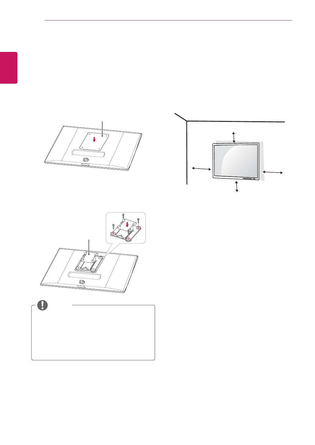
Install the monitor at least 10 cm away from the
wall and leave about 10 cm of space at each side
of the monitor to ensure sufficient ventilation. De-
tailed installation instructions can be obtained from
your local retail store. Alternatively, please refer
to the manual for how to install and set up a tilting
wall mounting bracket.
10 cm
10 cm
10 cm
10 cm
To install the monitor to a wall, attach a wall mount-
ing bracket (optional) to the back of the monitor.
Make sure that the wall mounting bracket is se-
curely fixed to the monitor and to the wall.
1
Use the screws and wall mounting bracket that
conform to VESA standards.
2
If you use screws longer than the standard
length, it may damage the inside of the prod-
uct.
3
A non-VESA standard screw may damage the
product and cause the monitor to fall. LG Elec-
tronics is not liable for any accidents relating
to the use of non-standard screws.
4
VESA compatible only with respect to screw
mounting interface dimensions and mounting
screw specifications.
5
Use the wall mount plate and fixing screws
that conform to VESA standards as specified
below.
y
784.8 mm or less
* Thickness of the wall mount plate: 2.6 mm
* Fixing screw: Diameter 4.0 mm x Pitch
0.7 mm x Length 10 mm
y
787.4 mm or more
* Use the wall mount plate and screws that
conform to VESA standards.
Installing the Wall Mount Plate
This monitor meets the specifications for the wall
mount plate or other compatible devices.
1
Place the screen face down. To protect the
screen from scratches, cover the surface with
a soft cloth.
2
Attach the clear sheet to the back of the moni-
tor and align it with the screw holes.
Clear sheet
(PET sheet)
3
Place the wall mount plate onto the monitor
and align it with the screw holes.
4
Tighten the four screws to fix the plate to the
monitor using a screwdriver.
Wall mount plate
y
The wall mount plate is sold separately.
y
For more information on installation, refer to
the wall mount plate's installation guide.
y
Be careful not to apply too much force while
mounting the wall mount plate as it may cause
damage to the screen
NOTE
ENGLISH
13
ASSEMBLING AND PREPARING
VESA (A x B) 100 x 100
Stand Screw M4
Required Screws 4
Wall Mount Plate
(Optional)
RW120
y
VESA (A x B)
A
B
y
Unplug the power cord before moving or install-
ing the monitor to avoid electric shock.
y
Installing the monitor on the ceiling or on a
slanted wall may result in the monitor falling off,
which could lead to injury. Use an authorized LG
wall mount and contact the local dealer or quali-
fied personnel.
y
Applying excessive force when tightening
screws may cause damage to the monitor. Dam-
age caused in this way will not be covered by
the product warranty.
y
Use the wall mounting bracket and screws that
conform to VESA standards. Damage caused by
the use or misuse of inappropriate components
will not be covered by the product warranty.
y
To prevent injury, this apparatus must be
securely attached to the wall in accordance
with the instrallation instructions. (This only
pertains to Australia and New Zealand.)
y
When measured from the back of the monitor,
the length of each installed screw must be 8 mm
or less.
Wall Mount Plate
Back of the Monitor
Screw
Dimensions
: M4 x L10
Wall Mount Plate
Back of the Monitor
Max 8 mm
CAUTION
y
Use the screws specified by VESA standards.
y
The wall mount kit includes the installation guide
and all necessary parts.
y
The wall mounting bracket is optional. You can
obtain optional accessories from your local dealer.
y
The length of the screw may differ for each wall
mounting bracket. Be sure to use the proper
length.
y
For more information, please refer to the user
manual for the wall mounting bracket.
NOTE
ENGLISH
14
ASSEMBLING AND PREPARING
Using the Kensington Lock
The connector for the Kensington security system
is located at the back of the monitor.
For more information on installation and usage,
refer to the Kensington lock owner's manual or visit
the website at http://www.kensington.com.
Connect the monitor to a table using the Kensing-
ton security system cable.
y
The Kensington security system is optional.
You can obtain optional accessories from most
electronics stores.
NOTE
ENGLISH
15
USING THE MONITOR
USING THE MONITOR
y
The following instructions are based on the
34UM95-PD model. Illustrations in this manual
may differ from the actual product.
Press the joystick button, go to Menu → Easy con-
trol → Input, and then select the input option.
y
Do not press the screen for a prolonged time.
This may cause image distortion.
y
Do not display a still image on the screen
for a prolonged time. This may cause image
retention. Use a screensaver if possible.
CAUTION
y
When connecting the power cord to the out-
let, use a grounded (3-hole) power strip or a
grounded power outlet.
y
The monitor may flicker when turned on in
an area where the temperature is low. This is
normal.
y
Sometimes red, green or blue spots may ap-
pear on the screen. This is normal.
NOTE
Connecting to a PC
y
This monitor supports the *Plug and Play fea-
ture.
* Plug and Play: A feature that allows you to add a
device to your computer without having to recon-
figure anything or install any manual drivers.
HDMI Connection
Transmits digital video and audio signals from your
PC to the monitor. Connect your PC to the monitor
using the HDMI cable as shown in the illustration
below.
D
C
-I
N
DP IN
HDMI IN
1
H
/
P
USB UP
USB IN 1
5 V 1.1 A
USB IN 2
5 V 0.5 A
USB IN 3
5 V 0.5 A
HDMI IN
2
D
C
-I
N
(19 V )
DP
IN
HDMI IN
1
H/P
US
B
U
P
HDMI IN
2
US
B IN 1
5 V 1.1 A
US
B IN
2
5 V 0.5 A
US
B IN
3
5 V 0.5 A
D
C-I
N
(19 V )
DP IN
HDMI
IN
1
H
/
P
US
B
U
P
HDMI IN
2
US
B IN 1
5 V 1.1 A
US
B IN
2
5 V 0.5 A
US
B IN
3
5 V 0.5 A
D
C
-I
N
(19 V )
DP IN
HDMI IN 1
H
/
P
US
B UP
HDMI IN 2
US
B IN 1
5 V 1.1 A
US
B IN
2
5 V 0.5 A
US
B IN
3
5 V 0.5 A
DC
-I
N
(19 V )
DP
IN
HDMI
IN 1
US
B
U
P
HDMI IN
2
US
B IN 1
5 V 1.1 A
US
B IN
2
5 V 0.5 A
US
B IN
3
5 V 0.5 A
DP OUT
5
V
0
.
9
A
A
UDI
O
IN
(
P
C)
5 V 0.5 A
H/P
US
B IN 1
US
B IN 2
USB IN
3
U
SB UP
DVI
-
D IN
DP IN
5 V 0.9 A
HDMI 1/
MHL
HDMI
2
DC
-I
N
(19 V )
DP IN
HDMI IN 1
H/P
US
B
U
P
HDMI IN 2
US
B IN 1
5 V 1.1 A
US
B IN
2
5 V 0.5 A
US
B IN 3
5 V 0.5 A
DC
-I
N
(19 V )
DP
IN
HDMI
IN 1
US
B UP
H
DMI IN
2
USB IN 1
5 V 1.1 A
USB IN 2
5 V 0.5 A
USB IN 3
5 V 0.5 A
y
Connecting your PC to the monitor using the
HDMI cable may cause device compatibility
issues.
y
Using a DVI to HDMI / DP(DisplayPort) to
HDMI cable may cause compatibility issues.
CAUTION
ENGLISH
16
USING THE MONITOR
DisplayPort Connection
Transmits digital video and audio signals from your
PC to the monitor. Connect the monitor to your PC
using the display port cable as shown in the illus-
tration below:
D
C
-I
N
(19 V )
DP IN
HDMI IN
1
H
/
P
USB UP
USB IN 1
5 V 1.1 A
USB IN 2
5 V 0.5 A
USB IN 3
5 V 0.5 A
HDMI IN
2
D
C
-I
N
(19 V )
DP
IN
HDMI IN
1
H/P
US
B
U
P
HDMI IN
2
US
B IN 1
5 V 1.1 A
US
B IN
2
5 V 0.5 A
US
B IN
3
5 V 0.5 A
D
C-I
N
(19 V )
DP IN
HDMI
IN
1
H
/
P
US
B
U
P
HDMI IN
2
US
B IN 1
5 V 1.1 A
US
B IN
2
5 V 0.5 A
US
B IN
3
5 V 0.5 A
D
C
-I
N
(19 V )
DP IN
HDMI IN 1
H
/
P
US
B UP
HDMI IN 2
US
B IN 1
5 V 1.1 A
US
B IN
2
5 V 0.5 A
US
B IN
3
5 V 0.5 A
DC
-I
N
(19 V )
DP
IN
HDMI
IN 1
US
B
U
P
HDMI IN
2
US
B IN 1
5 V 1.1 A
US
B IN
2
5 V 0.5 A
US
B IN
3
5 V 0.5 A
DP OUT
5
V
0
.
9
A
A
UDI
O
IN
(
P
C)
5 V 0.5 A
H/P
US
B IN 1
US
B IN 2
USB IN
3
U
SB UP
DVI
-
D IN
DP IN
5 V 0.9 A
HDMI 1/
MHL
HDMI
2
DC
-I
N
(19 V )
DP IN
HDMI IN 1
H/P
US
B
U
P
HDMI IN 2
US
B IN 1
5 V 1.1 A
US
B IN
2
5 V 0.5 A
US
B IN 3
5 V 0.5 A
DC
-I
N
(19 V )
DP
IN
HDMI
IN 1
US
B UP
H
DMI IN
2
USB IN 1
5 V 1.1 A
USB IN 2
5 V 0.5 A
USB IN 3
5 V 0.5 A
NOTE
y
There may be no video or audio output de-
pending on the DP (DisplayPort) version of the
PC.
y
For using Mini DP to DP (Mini DisplayPort to
DisplayPort) cable, it is recommended that you
use DisplayPort 1.2 cable.
Thunderbolt ( ) Connection
You can connect your high-resolution display or
high-performance data device to the monitor via a
Thunderbolt port. Connect your external device to
the monitor using the Thunderbolt cable as illus-
trated below.
D
C
-I
N
(19 V )
DP IN
HDMI IN
1
H
/
P
USB UP
USB IN 1
5 V 1.1 A
USB IN 2
5 V 0.5 A
USB IN 3
5 V 0.5 A
HDMI IN
2
D
C
-I
N
(19 V )
DP
IN
HDMI IN
1
H/P
US
B
U
P
HDMI IN
2
US
B IN 1
5 V 1.1 A
US
B IN
2
5 V 0.5 A
US
B IN
3
5 V 0.5 A
D
C-I
N
(19 V )
DP IN
HDMI
IN
1
H
/
P
US
B
U
P
HDMI IN
2
US
B IN 1
5 V 1.1 A
US
B IN
2
5 V 0.5 A
US
B IN
3
5 V 0.5 A
D
C
-I
N
(19 V )
DP IN
HDMI IN 1
H
/
P
US
B UP
HDMI IN 2
US
B IN 1
5 V 1.1 A
US
B IN
2
5 V 0.5 A
US
B IN
3
5 V 0.5 A
DC
-I
N
(19 V )
DP
IN
HDMI
IN 1
US
B
U
P
HDMI IN
2
US
B IN 1
5 V 1.1 A
US
B IN
2
5 V 0.5 A
US
B IN
3
5 V 0.5 A
DP OUT
5
V
0
.
9
A
A
UDI
O
IN
(
P
C)
5 V 0.5 A
H/P
US
B IN 1
US
B IN 2
USB IN
3
U
SB UP
DVI
-
D IN
DP IN
5 V 0.9 A
HDMI 1/
MHL
HDMI
2
DC
-I
N
(19 V )
DP IN
HDMI IN 1
H/P
US
B
U
P
HDMI IN 2
US
B IN 1
5 V 1.1 A
US
B IN
2
5 V 0.5 A
US
B IN 3
5 V 0.5 A
DC
-I
N
(19 V )
DP
IN
HDMI
IN 1
US
B UP
H
DMI IN
2
USB IN 1
5 V 1.1 A
USB IN 2
5 V 0.5 A
USB IN 3
5 V 0.5 A
(sold separately)
y
The maximum data transmission rate of each
port is 20 Gb/s.
y
Make sure to use a Thunderbolt (
) certified
cable. Otherwise, this may cause the device to
malfunction.
y
Thunderbolt (
) is supported in such environ-
ments as Windows 7, Windows 8 and New
Mac Pro (Over Mac OS 10.9.1).
y
The ASM driver on the Owner's Manual CD
must be installed to use the Thunderbolt (
)
port.
y
The ability to set up dual monitors using the
Thunderbolt (
) and daisy-chaining technology
depends on the performance of your video
card.
NOTE
ENGLISH
17
USING THE MONITOR
Connecting AV Devices
HDMI Connection
HDMI transmits digital video and audio signals
from your AV device to the monitor. Connect your
AV device to the monitor using the HDMI cable as
shown in the illustration below.
D
C
-I
N
(19 V )
DP IN
HDMI IN
1
H
/
P
USB UP
USB IN 1
5 V 1.1 A
USB IN 2
5 V 0.5 A
USB IN 3
5 V 0.5 A
HDMI IN
2
D
C
-I
N
(19 V )
DP
IN
HDMI IN
1
H/P
US
B
U
P
HDMI IN
2
US
B IN 1
5 V 1.1 A
US
B IN
2
5 V 0.5 A
US
B IN
3
5 V 0.5 A
D
C-I
N
(19 V )
DP IN
HDMI
IN
1
H
/
P
US
B
U
P
HDMI IN
2
US
B IN 1
5 V 1.1 A
US
B IN
2
5 V 0.5 A
US
B IN
3
5 V 0.5 A
D
C
-I
N
(19 V )
DP IN
HDMI IN 1
H
/
P
US
B UP
HDMI IN 2
US
B IN 1
5 V 1.1 A
US
B IN
2
5 V 0.5 A
US
B IN
3
5 V 0.5 A
DC
-I
N
(19 V )
DP
IN
HDMI
IN 1
US
B
U
P
HDMI IN
2
US
B IN 1
5 V 1.1 A
US
B IN
2
5 V 0.5 A
US
B IN
3
5 V 0.5 A
DP OUT
5
V
0
.
9
A
A
UDI
O
IN
(
P
C)
5 V 0.5 A
H/P
US
B IN 1
US
B IN 2
USB IN
3
U
SB UP
DVI
-
D IN
DP IN
5 V 0.9 A
HDMI 1/
MHL
HDMI
2
DC
-I
N
(19 V )
DP IN
HDMI IN 1
H/P
US
B
U
P
HDMI IN 2
US
B IN 1
5 V 1.1 A
US
B IN
2
5 V 0.5 A
US
B IN 3
5 V 0.5 A
DC
-I
N
(19 V )
DP
IN
HDMI
IN 1
US
B UP
H
DMI IN
2
USB IN 1
5 V 1.1 A
USB IN 2
5 V 0.5 A
USB IN 3
5 V 0.5 A
y
Using a DVI to HDMI / DP(DisplayPort) to
HDMI cable may cause compatibility issues.
NOTE
Connecting Peripherals
USB Cable connection - PC
The USB port on the product functions as a USB
hub.
y
Make sure to install the most recent Windows
OS service pack before using the product.
y
Peripheral devices are sold separately.
y
A keyboard, mouse, or USB device can be
connected to the USB port.
NOTE
Cautions When Using a USB Device
y
A USB device with an automatic recognition
program installed, or that uses its own driver,
may not be recognized.
y
Some USB devices may not be supported or
may not work properly.
y
It is recommended to use a USB hub or hard
disk drive with power supplied. (If the power
supply is not adequate, the USB device may
not be recognized properly.)
y
Since USB IN 2 and 3 only support USB 2.0,
it may not work when USB 3.0 devices are
connected.
CAUTION
ENGLISH
18
USING THE MONITOR
HDMI/DP (DisplayPort) connection
To use USB 3.0, connect the A-B type USB 3.0
cable of the product to the PC.
Peripheral devices connected to the USB IN port
can be controlled from the PC.
D
C
-I
N
(19 V )
DP IN
HDMI IN
1
H
/
P
USB UP
USB IN 1
5 V 1.1 A
USB IN 2
5 V 0.5 A
USB IN 3
5 V 0.5 A
HDMI IN
2
D
C
-I
N
(19 V )
DP
IN
HDMI IN
1
H/P
US
B
U
P
HDMI IN
2
US
B IN 1
5 V 1.1 A
US
B IN
2
5 V 0.5 A
US
B IN
3
5 V 0.5 A
D
C-I
N
(19 V )
DP IN
HDMI
IN
1
H
/
P
US
B
U
P
HDMI IN
2
US
B IN 1
5 V 1.1 A
US
B IN
2
5 V 0.5 A
US
B IN
3
5 V 0.5 A
D
C
-I
N
(19 V )
DP IN
HDMI IN 1
H
/
P
US
B UP
HDMI IN 2
US
B IN 1
5 V 1.1 A
US
B IN
2
5 V 0.5 A
US
B IN
3
5 V 0.5 A
DC
-I
N
(19 V )
DP
IN
HDMI
IN 1
US
B
U
P
HDMI IN
2
US
B IN 1
5 V 1.1 A
US
B IN
2
5 V 0.5 A
US
B IN
3
5 V 0.5 A
DP OUT
5
V
0
.
9
A
A
UDI
O
IN
(
P
C)
5 V 0.5 A
H/P
US
B IN 1
US
B IN 2
USB IN
3
U
SB UP
DVI
-
D IN
DP IN
5 V 0.9 A
HDMI 1/
MHL
HDMI
2
DC
-I
N
(19 V )
DP IN
HDMI IN 1
H/P
US
B
U
P
HDMI IN 2
US
B IN 1
5 V 1.1 A
US
B IN
2
5 V 0.5 A
US
B IN 3
5 V 0.5 A
DC
-I
N
(19 V )
DP
IN
HDMI
IN 1
US
B UP
H
DMI IN
2
USB IN 1
5 V 1.1 A
USB IN 2
5 V 0.5 A
USB IN 3
5 V 0.5 A
(sold separately)
(sold separately)
Thunderbolt ( ) connection
Peripheral devices connected to the USB IN port
can be controlled from the PC.
If you change the input on the menu while a device
is in connection via the Thunderbolt port, then the
device in connection via the USB port may not
work properly.
D
C
-I
N
(19 V )
DP IN
HDMI IN
1
H
/
P
USB UP
USB IN 1
5 V 1.1 A
USB IN 2
5 V 0.5 A
USB IN 3
5 V 0.5 A
HDMI IN
2
D
C
-I
N
(19 V )
DP
IN
HDMI IN
1
H/P
US
B
U
P
HDMI IN
2
US
B IN 1
5 V 1.1 A
US
B IN
2
5 V 0.5 A
US
B IN
3
5 V 0.5 A
D
C-I
N
(19 V )
DP IN
HDMI
IN
1
H
/
P
US
B
U
P
HDMI IN
2
US
B IN 1
5 V 1.1 A
US
B IN
2
5 V 0.5 A
US
B IN
3
5 V 0.5 A
D
C
-I
N
(19 V )
DP IN
HDMI IN 1
H
/
P
US
B UP
HDMI IN 2
US
B IN 1
5 V 1.1 A
US
B IN
2
5 V 0.5 A
US
B IN
3
5 V 0.5 A
DC
-I
N
(19 V )
DP
IN
HDMI
IN 1
US
B
U
P
HDMI IN
2
US
B IN 1
5 V 1.1 A
US
B IN
2
5 V 0.5 A
US
B IN
3
5 V 0.5 A
DP OUT
5
V
0
.
9
A
A
UDI
O
IN
(
P
C)
5 V 0.5 A
H/P
US
B IN 1
US
B IN 2
USB IN
3
U
SB UP
DVI
-
D IN
DP IN
5 V 0.9 A
HDMI 1/
MHL
HDMI
2
DC
-I
N
(19 V )
DP IN
HDMI IN 1
H/P
US
B
U
P
HDMI IN 2
US
B IN 1
5 V 1.1 A
US
B IN
2
5 V 0.5 A
US
B IN 3
5 V 0.5 A
DC
-I
N
(19 V )
DP
IN
HDMI
IN 1
US
B UP
H
DMI IN
2
USB IN 1
5 V 1.1 A
USB IN 2
5 V 0.5 A
USB IN 3
5 V 0.5 A
(sold separately)
(sold separately)
Connecting Headphones
Connect peripherals to the monitor via the head-
phones port. Connect as illustrated.
D
C
-I
N
(19 V )
DP IN
HDMI
IN
1
H
/
P
USB UP
USB IN 1
5 V 1.1 A
USB IN 2
5 V 0.5 A
USB IN 3
5 V 0.5 A
HDMI IN
2
D
C
-I
N
(19 V )
DP
IN
HDMI
IN
1
H/P
US
B
U
P
HDMI IN
2
US
B IN 1
5 V 1.1 A
US
B IN
2
5 V 0.5 A
US
B IN
3
5 V 0.5 A
D
C-I
N
(19 V )
DP IN
HDMI
IN
1
H
/
P
US
B
U
P
HDMI IN
2
US
B IN 1
5 V 1.1 A
US
B IN
2
5 V 0.5 A
US
B IN
3
5 V 0.5 A
D
C
-I
N
(19 V )
DP IN
HDMI IN 1
H
/
P
US
B UP
HDMI IN 2
US
B IN 1
5 V 1.1 A
US
B IN
2
5 V 0.5 A
US
B IN
3
5 V 0.5 A
DC
-I
N
(19 V )
DP
IN
HDMI
IN 1
US
B
U
P
HDMI IN
2
US
B IN 1
5 V 1.1 A
US
B IN
2
5 V 0.5 A
US
B IN
3
5 V 0.5 A
DP OUT
5
V
0
.
9
A
A
UDI
O
IN
(
P
C)
5 V 0.5 A
H/P
US
B IN 1
US
B IN 2
USB IN
3
U
SB UP
DVI
-
D IN
DP IN
5 V 0.9 A
HDMI 1/
MHL
HDMI
2
DC
-I
N
(19 V )
DP IN
HDMI IN 1
H/P
US
B
U
P
HDMI IN 2
US
B IN 1
5 V 1.1 A
US
B IN
2
5 V 0.5 A
US
B IN 3
5 V 0.5 A
DC
-I
N
(19 V )
DP
IN
HDMI
IN 1
US
B UP
H
DMI IN
2
USB IN 1
5 V 1.1 A
USB IN 2
5 V 0.5 A
USB IN 3
5 V 0.5 A
(sold separately)
y
Peripheral devices are sold separately.
y
If you use Angled earphones, it may cause
a problem with connecting another external
device to the monitor. Therefore, it is recom-
mended to use Straight earphones.
Angled Straight
y
Depending on the audio settings of the PC
and external device, headphones and speaker
functions may be limited.
NOTE
ENGLISH
19
INSTALLING THE LG MONITOR SOFTWARE
Insert the software CD included in the product packaging into your PC's CD drive and install the LG Monitor
Software.
1
Set up Internet Explorer as the default web
browser.
2
Click LG Monitor Software on the CD's main
screen. When the file download window ap-
pears, click Run. (Although the screen below
may differ depending on your operating sys-
tem or Internet Explorer version, the installa-
tion methods are the same.)
y
Windows 7 must be updated to Service Pack
1 or higher.
CAUTION
3
Follow the instructions to proceed with the
installation.
4
Check the I accept the terms of the agree-
ment checkbox on the License Agreement
screen and then click the Next button.
5
Select the program that you want to install.
ENGLISH
20
INSTALLING THE LG MONITOR SOFTWARE
y
Screen Split This program automatically splits
the program window as desired.
y
True Color Finder This program calibrates the
precise color output of the monitor to suit your
needs.
NOTE
6
The LG Monitor Software starts the installation
as shown below:
7
If the ASM driver has not been installed, the
driver will be installed automatically.
8
If the TUSB3410 driver has not been installed,
the driver will be installed automatically. Select
Install this driver software anyway (I) if the
Windows security message is displayed as be-
low.
9
The program you selected on the Select Fea-
tures page will install automatically.
10
When the installation is complete, restart your
system.
  • Page 1 1
  • Page 2 2
  • Page 3 3
  • Page 4 4
  • Page 5 5
  • Page 6 6
  • Page 7 7
  • Page 8 8
  • Page 9 9
  • Page 10 10
  • Page 11 11
  • Page 12 12
  • Page 13 13
  • Page 14 14
  • Page 15 15
  • Page 16 16
  • Page 17 17
  • Page 18 18
  • Page 19 19
  • Page 20 20
  • Page 21 21
  • Page 22 22
  • Page 23 23
  • Page 24 24
  • Page 25 25
  • Page 26 26
  • Page 27 27
  • Page 28 28
  • Page 29 29
  • Page 30 30
  • Page 31 31
  • Page 32 32
  • Page 33 33
  • Page 34 34
  • Page 35 35
  • Page 36 36
  • Page 37 37
  • Page 38 38

LG 34UM95 Owner's manual

Category
LED displays
Type
Owner's manual

LG 34UM95 is a high-performance monitor with a 34-inch IPS LED display, offering stunning visuals and immersive experiences. Equipped with AMD FreeSync technology, it synchronizes the refresh rate of the monitor with the frame rate of compatible graphics cards, virtually eliminating screen tearing and stuttering for smooth gameplay. Connect your devices with ease through its versatile connectivity options, including HDMI, DisplayPort, and Thunderbolt 3 ports.

Ask a question and I''ll find the answer in the document

Finding information in a document is now easier with AI