FBI
Fully Balanced
Integrated Amplifier
Instructions for Use
Owner’s Reference

This pr
oduct is manufactur
ed in the United States of America. Kr
ell
®
is a r
egister
ed trademark of Kr
ell
Industries, Inc., and is r
estricted for use by Kr
ell Industries, Inc., its subsidiaries, and authorized agents.
CAST™, Evolution CAST™, and Theater Thr
oughput™ ar
e trademarks of Kr
ell Industries, Inc. All other
trademarks and trade names ar
e r
egister
ed to their r
espective companies.
© 2006 by Kr
ell Industries, Inc. All rights r
eser
ved P/N 309094-W
FBI
Fully Balanced Integrated Amplifier
Instructions for Use
v
06.0
CONTACT
INFORMATION
This product complies with the
EMC directive (89/336/EEC)
and the low-voltage directive
(73/23/EEC).
Krell Industries, Inc.
45 Connair Road
Orange, CT 06477-3650 USA
TEL 203-298-4000
FAX 203-891-2028
E-MAIL krell@krellonline.com
WEBSITE http://www.krellonline.com
IMPORTANT SAFETY INSTRUCTIONS
1. Read Instructions.
2. Keep these Instructions.
3. Heed all Warnings.
4. Follow all Instructions.
5. Do not use this apparatus near water.
6. Clean only with dry cloth.
7. Do not install near any heat sources such as radiators, heat registers,
stoves, or other apparatus (including amplifiers) that produce heat.
8. Unplug this apparatus during lightning storms or when unused for long
periods of time.
9. Refer all servicing to qualified service personnel. Servicing is required
when the apparatus has been damaged in any way, such as a power-
supply cord or plug is damaged, liquid has been spilled or objects have
fallen into the apparatus, the apparatus has been exposed to rain or
moisture, does not operate normally, or has been dropped.
10. The FBI must be placed on a fir
m, level surface where it is not exposed
to dripping or splashing.
11. The ventilation grids on the top and bottom of the FBI must be unob-
structed at all times during operation. Do not place flammable material
above or beneath the pr
eamplifier
.
12. Before making connections to the FBI, ensure that the power is off and
other components are in mute or stand-by mode. Make sure all cable ter-
minations are of the highest quality, free from frayed ends, short circuits, or
cold solder joints.
13. THERE ARE NO USER SER
VICEABLE PARTS INSIDE A FULLY BAL-
ANCED INTEGRA
TED AMPLIFIER.
Please contact Krell if you have questions not addressed in this guide.

Krell FBI
3
Contents
Page
INTRODUCTION 5
REVOLUTIONARY KRELL CAST TECHNOLOGY 6
DEFINITION OF TERMS 8
UNPACKING 10
PLACEMENT 11
AC Power Guidelines
FRONT PANEL / REMOTE CONTROL DESCRIPTION 13
REMOTE CONTROL ONLY 15
Battery Installation and Removal
Remote Control Only Functions
BACK PANEL DESCRIPTION 18
CONNECTING THE FBI TO YOUR SYSTEM 20
Connection Steps
OPERATING YOUR
FBI
21
Amplifier Operation
Tape Input and Output
OPTIONAL CONFIGURATIONS
23
Configuring the FBI
for Theater Thr
oughput
Preamplifier Output
HOW TO TROUBLESHOOT SYSTEM NOISE 25
QUESTIONS AND ANSWERS 26
W
ARRANTY
27
RETURN AUTHORIZATION PROCEDURE 29
SPECIFICA
TIONS Back Cover

4 Krell FBI
Illustrations
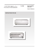
FIGURE 1 The FBI Front Panel 12
FIGURE 2 The FBI Remote Control 12
FIGURE 3 The FBI Back Panel 17
Page

Krell FBI
5
Introduction
Thank you for your purchase of the Krell FBI Remote Control Inte-
grated Amplifier. This fully integrated amplifier and preamplifier has
a fully balanced signal path from input to output and employs a
wide bandwidth design with low negative feedback for sonic accu-
racy throughout the frequency spectrum. All circuits, including the
amplifier output stage, operate in pure Class A mode.
The Fully Balanced Integrated Amplifier is a large-format integrat-
ed, and as such offers all the power and control afforded by big
Krell amplifiers in a convenient, integrated package that is simple
to operate. The remote control accesses all functions, while a 12 V
trigger connection allows the Fully Balanced Integrated Amplifier to
interface easily with other components. The Theater Throughput
feature provides easy integration into a home theater system.
This owner’s reference manual contains important information on
the placement, installation, and operation of the Fully Balanced
Integrated Amplifier. Please read this information carefully. A thor-
ough understanding of these details will help ensure satisfactory
operation and long life for your Fully Balanced Integrated Amplifier
and related system components.

6 Krell FBI
Current Audio Signal Transmission, termed CAST, is a revolutionary
method of connecting analog audio components for unparalleled sonic
performance. Innovative engineering combines the new Krell CAST cir-
cuitry with existing Krell Current Mode technology to create entire
CAST systems that reproduce music with incredible range, tonality,
and precision.
The Voltage Signal Transmission
and the Traditional Audio System
Traditionally, signal is transmitted in the voltage domain between two
components. In an audio system, each component is a discrete entity
with unique characteristics that act upon the musical signal independ-
ently. Each component is unaware of the other components in the sys-
tem. The cables that connect the components also have their own
electrical characteristics, which affect the sonic presentation of the
entire system. CAST transmission unifies individual components and
interconnects into an electrically-linked whole. The original signal
remains unaltered from source to speaker.
CAST Basics
Here is how a CAST audio system works. Internally
, each CAST source
transfers, or amplifies, current using Krell Current Mode circuitry. This
current signal is then output using CAST circuitry. When the signal is
received by a CAST input, Krell Current Mode circuitry again takes
over until the signal reaches the loudspeaker. By maintaining the musi-
cal signal in the current domain from beginning to end, an entire CAST
system behaves as if it is one component. W
ith CAST, circuit board
properties and signal transmission aberrations between components
are eliminated. Cable impedances and their effects on the transmitted
signal are non-existent.
How CAST and Krell Current Mode Interact
While CAST is a new method of transferring the musical signal be-
tween components, its origin stems from Krell Current Mode, the tech-
nology developed to transfer the musical signal within a component.
CAST combined with Krell Current Mode takes circuitry signal trans-
mission to the next evolutionary level. In essence, Krell Current Mode
Revolutionary Krell CAST Technology

maintains the integrity of the signal within the component and CAST
preserves the transmitted signal between components. Together, CAST
and Krell Current Mode technologies unify separate Krell components
into a
single global circuit. Krell Current Mode technology enjoys band-
width increases up to an order of magnitude greater than their voltage
based counterparts. This dramatic increase in circuit bandwidth deliv-
ers near perfection in the audible band that typically suffers from phase
distortions in voltage circuits.
CAST Cable Construction
A CAST system uses cables manufactured by Krell and other manu-
facturers specially licensed by Krell. Thin and flexible CAST cables are
constructed with the same build quality as other Krell components and
are aesthetically matched to the components that Krell manufactures.
An all-metal body and locking connectors with gold contacts are part
of the standard no-compromise specification developed for every
CAST cable made.
Evolution CAST
By employing r
evolutionary current mirror circuitry, the Evolution 222
components elevate the CAST technology to another level. This
advanced use of the technology increases the linearity, transient
speed, and bandwidth of the Evolution components while reducing the
distortion by an order of magnitude.
The Best Musical Performance
When you operate a CAST system, you will hear significant improve-
ments in every performance area: speed, precision, dynamic range,
depth and width of the sound stage, transient impact, tonal balance,
harmonic distortion, and more. The goal for CAST is the same compa-
ny goal used for all Krell products. Krell strives for the delivery of the
best performance of a musical event for you, using the full expression
of technology to date.
Krell FBI 7
R
evolutionary Krell CAST Technology,
continued

Definition of Terms
Following are the definitions of key terms used in your owner’s
reference manual.
Theater Throughput
Theater Throughput is a Krell configuration option that allows the
signal from a surround preamp/processor to pass through a Krell
preamplifier or integrated amplifier input at unity gain and sus-
pends operation of the preamp volume control. When Theater
Throughput is employed, control of the volume is accomplished
through the home theater processor.
Balanced
A symmetrical input or output circuit that has equal impedance
from both input terminals to a common ground reference point.
The industr
y standard for professional and sound r
ecording instal-
lations, balanced connections have 6 dB mor
e gain than single-
ended connections and allow the use of long interconnect cables.
Balanced connections are completely immune to induced noise
from the system or the envir
onment.
CAST and Evolution CAST
Krell Current Audio Signal Transmission, or CAST, is a proprietary Krell
circuit technology for connecting analog components, transmitting the
audio waveform between components in the current domain rather than
in the voltage domain. The speed and bandwidth pr
ovided by Krell
CAST and its circuitry update, Evolution CAST, yield accurate, realistic
music r
epr
oduction, enabling connected components to per
form as if
they are all part of a single circuit.
Single-ended
A two-wire input or output circuit. Use care when using single-
ended connections as the ground connection is made last and
broken first. Turn the system off prior to making or breaking sin-
gle-ended connections. Single-ended connections are not recom-
mended for connections r
equiring long cable r
uns.
CONFIGURATIONS
INPUT AND OUTPUT
CONNECTIONS
8 Kr
ell FBI

D
efinition of Terms,
continued
Off
The component is off when the AC power cord is unplugged from
the wall receptacle.
Stand-by Mode
A low power consumption status that keeps the audio circuits at
idle. When you plug the AC power cord into the wall receptacle,
and turn on the rear panel breaker switch, the red stand-by LED
illuminates. The component is now ready to be switched to the
operational mode. Krell recommends leaving the component in
the stand-by mode when it is not playing music.
Operational Mode
When the component is in the stand-by mode, and you press the
power button on the front panel or the power key on the remote
control, the blue power LED illuminates. The component is in the
operational mode and is ready to play music.
Krell Current Mode
A proprietar
y Krell circuit topology in which the audio gain stages
of a component operate in the current rather than voltage domain.
This unique technology pr
ovides the component with exceptional
speed and a wide bandwidth.
See also Revolutionary Krell CAST Technology, on pages 6-7.
OPERATION
TECHNOLOGY
Krell FBI
9

10
Kr
ell FBI
Unpacking
Two people are needed to remove the Fully Balanced Integrated
amplifier from its shipping box safely and easily.
1. Open the shipping carton and remove the top layer of foam.
The carton contains :
1 Fully Balanced Integrated Amplifier
1 AC power cord
1 12 VDC (12 V trigger) cable
1 T-10 Torx wrench
1 FBI remote control
2 AAA 1.5 V batteries
1 Packet containing the Quick Setup Guide and the warranty
registration card
2. Orient the shipping box so that one person stands at the front
of the amplifier and one person stands at the back of the
amplifier. Both people need to grab a pair of the cardboard
handle cutouts (one pair located at the front of the amplifier
and one pair located at the back of the amplifier) and simulta
-
neously lift the amplifier straight up, out of the car
ton. Bend
and lift with your knees, not your back.
3. Place the amplifier in a safe location and remove the protective
plastic wrapping.
If any of the listed items are not included in the shipping box, please
contact your authorized Krell dealer or distributor.
Save all packing materials. If you need to ship your FBI in the future,
r
epack the unit in its original packaging to prevent shipping damage. See
Return Authorization Procedure, on page 29, for more information.
Notes

Krell FBI
11
Placement
Before you install the FBI into your system, please review the fol-
lowing guidelines to choose the proper location for the FBI. This
will facilitate a clean, trouble-free installation.
The FBI does not require any type of special rack or cabinet for
installation. For the dimensions of the FBI,
see Specifications, on
the back cover.
Place the FBI on a firm, level surface, away from excessive heat,
humidity, or moisture. The FBI requires at least two inches (5 cm)
of clearance on each side and at least eight inches (20 cm) of
clearance above and below the component to provide adequate
ventilation. The ventilation grids on the FBI must be unobstructed.
If the amplifier is placed in a closed cabinet, more than eight inch-
es (20 cm) of clearance may need to be provided above and
below the component, or small fans may be needed to increase
ventilation. The air space between the chassis and shelf must be
unobstructed.
The Fully Balanced Integrated amplifier drives the lowest imped-
ances with ease. When impedance is added due to long speaker
cable lengths, amplifier power is wasted in the cable. Long speak
-
er cables r
educe the maximum power that is delivered in the
speakers.
The Fully Balanced Integrated amplifier needs to be operated
from a dedicated AC power line rated at a minimum of 20 amps.
Use only the power cor
d pr
ovided with the Fully Balanced
Integrated amplifier to make this connection. Operation with a
power cor
d other than the one supplied by Krell can induce noise,
limit current, and otherwise impair the amplifier’s ability to perform
optimally. The use of the Fully Balanced Integrated amplifier with
devices designed to alter or stabilize the AC power also may
impair the amplifier’s ability to perform optimally.
AC Power
Guidelines

12 Krell FBI
Figure 1 The FBI Front Panel
Figure 2 The FBI Remote Control
Power
1 Power Button or Key
2 Power Indicator
3 Stand-by LED
4 Infrared Sensor
Analog Devices
5 C-1 Button, Key
and LED
6 B-1 Button, Key
and LED
7
S-1, S-2, S-3, and
B-1, Buttons, Keys
and LEDs
8 Tape Button or Key
9 Tape LED
Mode Indicators
10
Mute Button or Key
11 Mute LED
Volume
12 Level Knob or Keys
Display
13 Front Panel Display
Volume Adjustment
Functions (remote only)
14 Bal (Balance) keys
Note
The numbered remote con-
tr
ol keys function with the
FBI. The CD player keys on
this r
emote contr
ol activate
some Krell source compo-
nents.
4
13
12

Front Panel/Remote Control Description
S
ee Figures 1 and 2 on page 12
Krell FBI 13
Power, analog input selections, and volume control accessed via
the FBI front panel buttons or remote control keys are described
below. The front panel display shows volume and balance levels,
and Theater Throughput status. Most front panel functions also are
activated via the keys on the remote. The volume adjustment func-
tion, a special operational feature of the remote control only, is
described on page 16:
1 Power Button or Key
Use this button or key to switch the FBI between the stand-by
and the operational modes.
2 Power Indicator
The blue power indicator illuminates when the FBI is in the opera-
tional mode. The blue power indicator also flashes when any
remote control key is pressed.
3 Stand-by LED
The amplifier is in the stand-by mode and ready to be switched to
the operational mode, when the FBI is plugged into a standar
d
AC wall receptacle, the back panel power breaker switch (24) is in
the up position, and the red stand-by LED illuminates.
4 Infrar
ed Sensor
The infrared sensor receives commands from the FBI remote con-
trol. For proper remote control operation, make sure that nothing
is obstr
ucting the infrared sensor.
5 C-1 Button, Key
, and LED
Selects a CAST source component (C-1) via a CAST connector.
When the button or key is selected, the r
ed LED illuminates.
6 B-1 Button, Key, and LED
Selects a balanced analog source component via an XLR connec-
tor. When the button or key is selected, the red LED illuminates.
7 S-1, S-2, and S-3 Buttons, Keys, and LEDs
Selects a single-ended analog sour
ce component via single-
ended RCA connectors. When the button or key is selected, the
red LED illuminates.
POWER
ANALOG
SOURCE
COMPONENTS

14 Krell FBI
F
ront Panel Description,
continued
8 Tape Button or Key
Use this button or key to playback pre-recorded tapes and com-
pare the output signal of an analog tape recorder to an audio
source.
See Tape Input and Output, on page 22.
9 Tape LED
The red tape monitor LED illuminates when the tape monitor is
activated. The LED does not illuminate when an audio source is
activated.
10 Mute Button or Key
Use this button or key to interrupt the signal of the input you have
selected. To unmute, press the mute button or key again.
11 Mute LED
The r
ed mute LED illuminates when you press the mute button or
key.
12 Level Knob / Level Keys
The level knob on the front panel or the level keys on the remote
control adjust the amplifier output level. The output level is indi-
cated numerically on the front panel display (13), with a range
from 0-151.
13 Fr
ont Panel Display
The front panel display shows volume and balance levels and
Theater Throughput status.
MODE INDICATORS
VOLUME ADJUSTMENT
FUNCTIONS

Remote Control Only
See Figure 2 on page 12
Krell FBI 15
The remote control uses 2 AAA-size 1.5 Volt batteries. Batteries are
included with the shipment. To install the batteries:
1. Remove the remote control backplate, using the supplied T-10 Torx
wrench.
2. Install the batteries, following the battery position diagram on the
plastic battery receptacle.
3. Replace and secure the backplate.
Replace batteries when remote control function becomes intermittent.
Remove batteries if the remote control is not used for a long period of
time. Battery leakage can damage the remote control.
Notes
Battery
Installation
and
Removal

R
emote Control Functions,
continued
16
Kr
ell FBI
The FBI remote control accesses complete power amplifier and
preamplifier functions. The volume adjustment function is unique
to the FBI remote control.
14 Bal (Balance) Keys
Use these keys to shift the balance to the left or the right channel.
Balance level is indicated in the front panel display (13). To display
balance, push any key on the remote.
The front panel display indicates:
-
C-
when the system is balanced. If the system is not balanced, the
fr
ont panel display indicates that the balance is right or left of
center and by how much, on a scale of
1 (least out of balance) to
5 (most out of balance).
Example: A display of:
- -
3
means that the balance is moderately right of center. A display
of:
5 - -
means the balance is sever
ely left of center.
The numbered remote control keys function with the FBI. The CD player
keys on this remote control activate some Krell source components.
Note
Remote Control
Only Functions
VOLUME ADJUSTMENT
FUNCTION

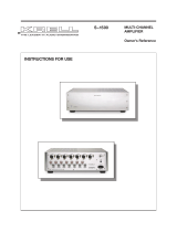
Figure 3 The FBI Back Panel
Krell FBI 17
Amplifier Channel Outputs
15 Left and Right
Loudspeaker Outputs
Analog Inputs
16 Left and Right
CAST Inputs
17 Left and Right Balanced
Analog Inputs
18
Left and Right Single-
ended Analog Inputs
19 Left and Right Tape Inputs
Analog Outputs
20
Left and Right T
ape
Outputs
21 Left and Right
Preamplifier Outputs
Remote Back Panel Connections
22 RC-5 In
23 12 VDC In/Out
(12 V Trigger)
Power
24 Back Panel Power
Breaker Switch
25
IEC Connector
Convenient Lifting Device
26 Handles

Back Panel Description
S
ee Figure 3 on page 17
18 Krell FBI
The FBI back panel provides connections for all inputs and out-
puts, power on/off, and additional remote connections.
15 Left and Right Loudspeaker Outputs
Two pairs of loudspeaker binding posts are available for each
channel of amplification, facilitating a power-bi-wire connection to
the loudspeaker. Each pair of binding posts is connected internal-
ly via copper buss bars. When only one set of binding posts is
used, the connection can be made from either pair of binding
posts. See the loudspeaker and/or cable manufacture’s instruc-
tion manual for more information about power-bi-wire connec-
tions.
The loudspeaker binding posts accept spade lugs only. Bare wire,
banana lugs, or pins will not work. Use the red terminal for the
positive connection and the blue terminal for the negative con-
nection.
16 Krell CAST Inputs
The FBI is equipped with one pair of Krell CAST inputs via 4-pin
bayonet connectors. Krell CAST inputs allow the Fully Balanced
Integrated amplifier to be connected to any Krell CAST-equipped
component.
17 Left and Right Balanced Analog Inputs
The FBI is equipped with one pair of balanced (B-1) inputs via
XLR connectors.
18 Left and Right Single-Ended Analog Inputs
The FBI is equipped with three pairs of single-ended (S-1,
S-2, or S-3) inputs via RCA connectors.
19 Left and Right Tape Inputs
The FBI is equipped with a pair of single-ended tape inputs via
RCA connectors.
20 Left and Right Tape Outputs
The
FBI
is equipped with a pair of single-ended tape
outputs via RCA connectors.
21 Left and Right Preamp Outputs
The FBI is equipped with a pair of single-ended pre-
amplifier outputs.
AMPLIFIER CHANNEL
OUTPUTS
ANALOG INPUTS
ANALOG OUTPUTS

Krell FBI
19
22 RC-5 In
The FBI is equipped with an RC-5 input that makes custom instal-
lation easy and secure by accepting baseband RC-5 input com-
mands from hardwired remote controllers.
23 12 VDC In/Out (12 V Trigger)
The FBI has one output that sends, and one input that receives 12 VDC
power on/off (12 V trigger) signals to and from other Krell components,
and other devices that incorporate a 12 V trigger. This allows you to
turn other components on or off, or to and from stand-by. When an
amplifier is switched to operational mode and is connected to other
components through the 12 V trigger, it sends a signal that will switch
other components, allowing whole systems or parts of systems to be
easily coordinated. Mono 3.5 mm connectors are used in the following
configuration: Tip = +12 V, Sleeve = GND.
When the FBI is in the operational mode, the 12 V trigger provides 12 Volts
of DC output. When the FBI is in the stand-by mode or off, the DC output
is 0 Volts. A maximum of 30 mA is available from the 12 V trigger output.
Consult the owner's reference of the components used in a custom instal-
lation to take full advantage of the remote capabilities of the FBI.
24 Back Panel Power Br
eaker Switch
Place the back panel power breaker switch in the up position to
put the FBI in stand-by mode. Krell recommends that the amplifier
remain on, in stand-by mode, when not in use.
25 IEC Connector
The connector is for use with the provided AC power cord.
26 Handles
The FBI is equipped with two handles to help to move the inte
-
grated amplifier easily and safely.
Notes
REMOTE
CONNECTIONS
CONVENIENT
LIFTING DEVICE
POWER

20 Krell FBI
Krell recommends using balanced interconnect cables. Balanced
interconnect cables not only can minimize sonic loss but are also
immune to induced noise, especially with installations using long
cables. Balanced connections have 6 dB more gain than single-
ended connections. When level matching is critical, keep this gain
value in mind.
Follow these steps to connect the FBI to your system.
1. Make sure all power sources and components are off before
connecting inputs and outputs.
2. Neatly organize the wiring between the FBI and all system
components. Separate AC wires from audio cables to
prevent hum or other unwanted noises from being introduced
into the system.
3. Connect the left and right outputs of your source components
to the appropriate analog inputs (15, 16, 17) on the FBI. The
FBI is equipped with one CAST input (C-1) (16), one balanced
input (B-1) (17), three single-ended inputs (S-1, S-2, or S-3)
(18), and one tape input (19). The C-1, B-1, S-1, S-2, and S-3
inputs can be configur
ed for Theater Throughput.
See
Optional Configurations, on page 23 for information on con-
figuring an input for Theater Throughput.
Pin 1 Shield (ground)
Pin 2 Non-inverting (hot) (0°)
Pin 3
Inver
ting (cold) (180°)
4. Connect the loudspeaker cables to the loudspeaker binding
posts (15) of the FBI, located on the back panel. Loudspeaker
binding posts accept spade lugs only.
6. Plug the AC power cord into the IEC connector (25) on the
back panel of the FBI. Plug the other end of the power cord
into the AC wall receptacle.
Connecting the FBI
to Your System
USING BALANCED
CONNECTIONS
Connection
Steps
Pin assignments for the
XLR connectors
Page is loading ...
Page is loading ...
Page is loading ...
Page is loading ...
Page is loading ...
Page is loading ...
Page is loading ...
Page is loading ...
Page is loading ...
Page is loading ...
/