ALL phases of this installation must comply with NATIONAL, STATE AND LOCAL CODES
IMPORTANT — This Document is customer property and is to remain with this unit. Please return to service information
pack upon completion of work.
HAZARDOUS VOLTAGE - DISCONNECT POWER BEFORE SERVICING
WARNING:
Installer’s Guide
General Information 1
Unit Installation 3
Upflow 3
Downflow 4
Horizontal Left 6
Horizontal Right 7
Duct Connections 8
Refrigerant Piping 8
Brazing to Evaporator 8
Condensate Drain Piping 9
Electrical — Power Wiring 10
Control Wiring 10
Hook-up Diagrams 11
Outline Drawing 14
Checkout Procedures 16
Contents
A. GENERAL INFORMATION
WARNING
!
THIS INFORMATION IS FOR USE BY INDIVIDUALS
HAVING ADEQUATE BACKGROUNDS OF ELECTRICAL
AND MECHANICAL EXPERIENCE. ANY ATTEMPT TO
REPAIR A CENTRAL AIR CONDITIONING PRODUCT
MAY RESULT IN PERSONAL INJURY AND/OR PROP-
ERTY DAMAGE. THE MANUFACTURER OR SELLER
CANNOT BE RESPONSIBLE FOR THE INTERPRETA-
TION OF THIS INFORMATION, NOR CAN IT ASSUME
ANY LIABILITY IN CONNECTION WITH ITS USE.
CAUTION
!
To prevent shortening its service life, the air handler
should not be used during the finishing phases of con-
struction. The low return air temperatures can lead to
the formation of condensate. Condensate in the pres-
ence of chlorides and fluorides from paint, varnish,
stains, adhesives, cleaning compounds, and cement
creates a corrosive condition which may cause rapid
deterioration of the cabinet and internal components.
These instructions do not cover all variations in systems
or provide for every possible contingency. Should fur-
ther information be desired or particular problems arise
which are not covered sufficiently by this manual, con-
tact your local distributor or the manufacturer as listed
on the air handler nameplate.
These air handlers are shipped from the factory in the
upflow or horizontal right configuration and are fully
convertible to downflow or horizontal left. Refer to
Section B beginning on page 3 for additional informa-
tion.
INSPECTION
Check carefully for any shipping damage. This must
be reported to and claims made against the transpor-
tation company immediately. Check to be sure all
major components are in the unit. Any missing parts
should be reported to your supplier at once, and re-
placed with authorized parts only.
CAUTION
!
Cardboard packing material must be removed from in-
side the blower assembly before starting the unit.
Failure to do so may cause indoor blower motor failure.
INSTALLATION LIMITATIONS & RECOMMENDATIONS
The general location of the air handler is normally
selected by the architect, contractor and/or home owner
for the most effective application and satisfaction.
NOTE: CONDENSATION MAY OCCUR ON THE SUR-
FACE OF THE AIR HANDLER WHEN INSTALLED IN AN
UNCONDITIONED LOCATION. WHEN UNITS ARE IN-
STALLED IN UNCONDITIONED SPACES, VERIFY THAT
ALL ELECTRICAL AND REFRIGERANT LINE PEN-
ETRATIONS ON THE AIR HANDLER ARE SEALED
COMPLETELY.
18-GE08D1-7
Convertible Air Handlers
1-1/2 – 5 Ton
2/4TEC3F18B1000A 2/4TEC3F42C1000A
2/4TEC3F24B1000A 2/4TEC3F48B1000A
2/4TEC3F30B1000A 2/4TEC3F55B1000A
2/4TEC3F36B1000A 2/4TEC3F60B1000A
© 2008 Trane 2 18-GE08D1-6
Installer’s Guide
Manual D, Manual S and Manual RS along with the
air handler Product Data and Service Facts for addi-
tional information.
5. The area around refrigerant lines must be sealed
and electrical inlets need to be sealed at both the
low and the high voltage.
6. It is recommended that the outline drawing be
studied and dimensions properly noted and checked
against selected installation site. By noting in ad-
vance which knockouts are to be used, proper clear-
ance allowances can be made for installation and
possible future service.
7. Allow a minimum of 21 inches clearance in
front of the air handler to permit service and re-
moval of filter.
8. When air handler with supplementary heater is to
be installed in the downflow position on combus-
tible flooring an accessory subbase (TAYBASE101
for 2TEC3F18-36B, TAYBASE102 for 2TEC3F55 and
TAYBASE100 for 2TEC3F42B-60B) must be used.
See Figure 1.
9. If supplementary heat is to be added, power supply
must be sufficient to carry the load. In addition,
minimum air flow settings, unit and duct clearances
to combustible material must be maintained as
stated on the air handler rating nameplate.
These air handlers are suitable for installation in a
closet, alcove or utility room with free, non-ducted, air
return, using the area space as a return air plenum.
With ducted supply air, if the minimum clearances to
combustible materials and service access are observed,
the above installations are suitable.
This area may also be used for other purposes, includ-
ing an electric hot water heater – but in no case shall
a fossil fuel device be installed and/or operated in
the same closet, alcove or utility room.
In addition, these air handlers are suitable for installa-
tion in an attic, garage or crawl space with ducted sup-
ply and return air.
This equipment has been evaluated in accordance with
the Code of Federal Regulations, Chapter XX, Part 3280
or the equivalent. “SUITABLE FOR MOBILE HOME
USE.”
For proper installation the following items must be con-
sidered:
1. If adequate power is available and correct according
to nameplate specifications.
2. Insulate all ducts, particularly if unit is located out-
side of the conditioned space.
3. Pursuant to Florida Building Code 13-610.2.A.2.1,
this unit meets the criteria for a factory sealed
air handler.
4. To ensure maximum efficiency and system perfor-
mance, the existing supply and return duct system
static pressures must not exceed the total available
static pressure of the air handler. Reference ACCA
B
A
JOIST
JOIST
JOISTS
HEADER
JOISTS
HEADER
NAILS
REAR
FLANGE
FRONT OF
UNIT
HEADER
1"
NAILS
HEADER
MIN. SPACING TO
ANY COMBUSTIBLE
MATERIAL.
1"
APPROX. 3/4" FLANGES ON FIELD
FABRICATED DUCT OR PLENUM
ONE INCH DUCT SPACERS
FLOOR
SUBBASE
UNIT
AIR HANDLER SUBBASE
1
FLOOR OPENING - SIZE
MODEL NO. A B
TAYBASE100 23-3/4 14-13/16
TAYBASE101 21-3/4 14-13/16
TAYBASE102 26-3/4 14-13/16
18-GE08D1-6 3
Installer’s Guide
CAUTION
!
For air handlers not equipped with a factory installed
electric heater, a field installed heater is available from
Trane. Only heaters built by Trane are approved for use
in the air handler. These heaters have been designed
and tested in accordance with UL standards to provide
safe and reliable operation. A list of approved heaters
is provided on the air handler rating nameplate. Heat-
ers that are not factory approved could cause damage
and are not covered under equipment warranty.
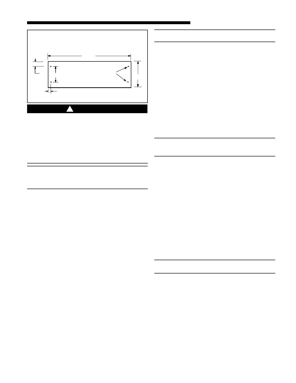
NOTE: If air handler is used WITHOUT a supplementary
electric heater, a sheetmetal plate is required to cover
the open hole in the airflow system. See Figure 2. Also
seal the cabinet air tight where the wire enters.
10. If the unit is installed without a return air duct, ap-
plicable local codes may limit this air handler to in-
stallation only in a single story residence and
within conditioned space.
11. If the outdoor unit is to be installed later, or by oth-
ers, then installation of the air handler must be
made to allow access for refrigerant lines, or attach
refrigerant lines to air handler when installing.
12. Make sure there are provisions for installing con-
densate drain lines.
13. If side, front or rear return is required, air handler
must be elevated or placed on a plenum
(TAYPLNM100 for 2/4TEC3F18 - 48B, 2/4TEC3F60B
or TAYPLNM101 for 2/4TEC3F55B). Connecting re-
turn duct directly to the side, front or rear of the
cabinet is not approved.
14. Route refrigerant and condensate drain lines away
from air handler so they do not interfere with ac-
cess panels and filters.
15. When external accessories are used, the additional
height and width requirements must be considered
in the overall space needed.
16. These units are not approved for outdoor installa-
tion.
17. These units are approved for draw-through appli-
cation only.
NOTE: No atomizing style humidifier is allowed in the
return plenum with the use of this unit.
18. Flow-through Bypass Humidifiers
Excessive bypass air may cause water blow-off,
which will adversely affect system operation and air
cleaner performance. To verify bypass airflow, fol-
low the Bypass Humidifier Pre-Installation Check-
out and Set-Up Procedures available through your
local distributor. Ask for publication number 18-
CH37D1-1.
Steam and Flow-through Fan Power Duct-
mounted Humidifiers
Follow the humidifier installation instructions.
These should only be installed on the supply air
side of the system.
B. TWO PIECE CABINET DISASSEMBLY
(OPTIONAL)
NOTE: For easier installation into tight areas, the 4
and 5 ton air handlers can be disassembled and reas-
sembled after moved to an attic or other space.
Steps for disassembly and reassembly (See Figures 3
and 4)
1. Disconnect wiring.
2. Remove center bracket.
3. Remove blower assembly.
4. Remove coil.
5. Cut foil tape - minimum 3" foil tape.
6. Remove top 8 screws. See Figure 3.
7. Lift upper section.
8. Set air handler in place.
9. Attach screws - insure gaskets are aligned
along flange.
10. Use foil tape to seal - use minimum 3" foil tape.
11. Insert coil.
12. Reinstall blower assembly.
13. Reinstall center bracket.
14. Reconnect wiring.
NOTE: In Downflow, remove coil before blower by
reversing steps 4 and 5.
C. UNIT INSTALLATION
UPFLOW
a. For maximum efficiency, the horizontal drip
tray should be removed. See Figures 6, 7 and
8. Drip tray removal requires that the coil be
removed by sliding the coil out on the coil
channel supports. The drip tray is detached by
removing the two screws at the drain pan and
the two screws holding the two brackets at the
From Dwg. 21B140413
4"
6"
17"
1"
3/8"
1/4" HOLES (4)
ACCESSORY BAY99X123
IF AIRHANDLER IS USED
WITHOUT A FACTORY FURNISHED
SUPPLEMENTARY HEATER, A PLATE IS REQUIRED TO COVER
THE OPEN HOLE IN THE AIR FLOW SYSTEM
2
© 2008 Trane 4 18-GE08D1-6
Installer’s Guide
top of the coil. Remove the two screws holding
the two brackets at the top of the coil. Remove
drip tray by gently breaking the seal between the
drip tray and drain pan.
b. Remove the factory installed baffle assembly
from the apex of the coil by using a 5/16"
nutdriver to remove the screws. Replace this
baffle with the factory supplied narrow coil
baffle using the screws removed previously
(See Figure 5). Reinstall coil assembly.
CAUTION
!
When installing the narrow coil baffle, make sure to
align the baffle up with the holes so NOT to puncture
the coil tubing.
c. Position unit on Pedestal or other suitable foun-
dation. If Pedestal is not used, a frame strong
enough to support the total weight must be pro-
vided. Provide a minimum height of 14 inches for
proper unrestricted airflow.
d. If a return air duct is connected to the air han-
dler, it must be the same dimensions as shown in
the outline drawing.
e. On units with sheetmetal returns: Return ple-
num should be flanged. Sheetmetal screws must
be 1/2" in length or shorter.
f. No sheetmetal screws may be used to attach re-
turn duct work on the side of the unit.
g. Pedestal and unit should be isolated from the
foundation using a suitable isolating material.
h. Openings where field wiring enters the
cabinet must be completely sealed. Location
of power entry is shown on the outline drawing.
Use 2.5" clear stickers to seal all unused electri-
cal knockouts. See Figure 11.
i. After ductwork connections are made, seal air-
tight and per local codes.
DOWNFLOW
a. For maximum efficiency, the horizontal drip
tray should be removed. See Figures 6, 7 and
8. Tray removal requires that the coil be re-
moved by sliding the coil out on the coil chan-
nel supports. The tray is detached by removing
the two screws at the drain pan and the two
screws holding the two brackets at the top of
2 PIECE WRAPPER SPEAR
4
Remove
and
Discard
Replace
with
Narrow
Baffle
FOR MAXIMUM EFFICIENCY ON
HORIZONTAL LEFT,
UPFLOW AND DOWNFLOW
5
CLOSEUP OF SPEAR LOCATIONS
3
1
2
3
4
SCREWS 5-8
LOCATED ON
LEFT SIDE
18-GE08D1-6 5
Installer’s Guide
the coil. Remove drip tray by gently breaking
the seal between the drip tray and drain pan.
b. Remove the factory installed baffle assembly
from the apex of the coil by using a 5/16"
nutdriver to remove the screws. Replace this
baffle with the factory supplied narrow coil
baffle using the screws removed previously
(See Figure 5).
CAUTION
!
When installing the narrow coil baffle, make sure to
align the baffle up with the holes so NOT to puncture
the coil tubing.
NOTE: INSTALLATION OF THE DOWNFLOW BAFFLE
KIT INCLUDED WITH UNIT IS REQUIRED ON
DOWNFLOW APPLICATIONS. SEE FIGURE 9.
c. Remove front shield by removing screws on right
side. Make sure to reinstall front shield after
baffle changes. See Figure 9.
d. Detach the coil from the drain pan by removing 4
screws as shown in Figure 9.
e. Remove the front triangular baffle from the coil
and install the 1/2" wide gasket provided per
Figure 9. Trim the gasket length to fit the baffle.
Reinstall the baffle to coil, with gasket material
compressed against the coil.
f. Install the water blow-off baffles provided on each
side of the coil with the flange at the top as
shown in Figure 9. The bottom of the baffle is to
be as close to the bottom of the coil as possible.
g. Install the 7/8" wide gasket in each side of the
drain pan as shown in Figure 9.
h. Place the 2 water diverter baffles (5 ton model
only) underneath the coil on the inside edge of
the drain pan, Figure 9. Fill the bend in the
baffle which fits the inner edge of the drain pan
with non-acetic acid RTV type adhesive/sealant
before installing the baffle.
i. The unit is then placed with the blower side
down and the coil is replaced on the coil channel
supports with the drain connections at the
bottom. The unit is now in downflow position
with front access. Do not reattach coil support
tab.
j. When air handler with supplementary heater is
to be installed in the downflow position on
combustible flooring an accessory subbase
(TAYBASE101 for 2TEC3F18B-36B,
TAYBASE102 for 2TEC3F55B and TAYBASE100
for 2TEC3F42B-60B) must be used. See Figure
1.
HORIZONTAL DRIP TRAY REMOVAL
7
DRIP TRAY BRACKET REMOVAL
8
DRIP PAN FOAM REMOVAL
6
6 18-GE08D1-7
Installer’s Guide
k. If a return duct is connected to the air handler, it
must be the same dimensions as the return
opening shown in the outline drawing.
l. On units with sheet metal returns: Return
plenum should be flanged. Sheetmetal screws
must be 1/2" in length or shorter.
m. No sheetmetal screws may be used to attach
return ductwork on the side of the unit.
n. Openings where field wiring enters the cabi-
net must be completely sealed. Location of
power entry is shown on the outline drawing.
Use 2.5" clear stickers to seal all unused electri-
cal knockouts. See Figure 11.
o. After ductwork connections are made, seal air-
tight and per local codes.
HORIZONTAL LEFT
a. To convert the unit to horizontal left, front ac-
cess, slide the coil out on the coil channel sup-
ports and rotate the complete coil 180 degrees.
b. For maximum efficiency and Customer ease of
filter maintenance, it is recommended that a
properly sized remote filter grille be installed
for horizontal applications. Airflow should not ex-
ceed the face velocity of the filter being used.
The factory installed filter should then be
removed from the unit. Remove the factory
installed baffle assembly from the apex of the coil
by using a 5/16" nutdriver to remove the hex
head screws. Replace this baffle with the factory
supplied narrow coil baffle using the screws re-
moved previously. See Figure 5.
CAUTION
!
When installing the narrow coil baffle, make sure to
align the baffle up with the holes so NOT to puncture
the coil tubing.
c. The coil is then inserted back into the cabinet on
the opposite side coil channel supports. The unit
is now horizontal left with front access. Do not
reattach coil support tab.
d . If the unit is suspended, it must be supported
from the bottom near both ends as well as the
middle to prevent sagging. The service access
must remain unobstructed. If the unit is sup-
ported along the length of the front and back
DOWNFLOW BAFFLE KIT
X
X
7/8" GASKET
SCREWS TO
REMOVE COIL
SCREWS TO
REMOVE COIL
DISCARD HORIZONTAL
DRIP TRAY
1/2" GASKET
INSIDE SURFACE
OF BAFFLE
7/8" GASKET
SECT. X-X
(TYP. BOTH SIDES)
FILL WITH SEALANT
WATER
BLOW-OFF
BAFFLES
ATTACH WITH
2 SCREWS
EACH SIDE
WATER
DIVERTER
BAFFLES
(5TON ONLY)
9
18-GE08D1-7 7
Installer’s Guide
j. No sheetmetal screws may be used to attach re-
turn ductwork on the side of the unit.
k. Openings where field wiring enters the
cabinet must be completely sealed. Location
of power entry is shown on the outline drawing.
Use 2.5" clear stickers provided to seal all unused
electrical knockouts. See Figure 11.
l. After ductwork connections are made, seal air-
tight and per Local codes.
HORIZONTAL RIGHT
a. For maximum efficiency and Customer ease of
filter maintenance, it is recommended that a
properly sized remote filter grille be installed
for horizontal applications. Airflow should not ex-
ceed the face velocity of the filter being used.
The factory installed filter should then be
removed from the unit.
b. Unit is shipped from the factory in the upflow or
horizontal right configuration. Unit conversion is
not required.
c. If the unit is suspended, it must be supported
from the bottom near both ends as well as the
middle to prevent sagging. The service access
must remain unobstructed. If the unit is sup-
ported along the length of the front and back
with rails, the air handler only needs to be sus-
pended at both ends. See Figure 10.
with rails, the air handler only needs to be sus-
pended at both ends. See Figure 10.
If the unit is not suspended it must be supported
as mentioned above and isolated carefully to pre-
vent sound transmission. Vibration isolators (pur-
chased locally) must be placed under the unit.
e. It is always recommended that an auxiliary drain
pan be installed under a horizontal air handler
(See Condensate Piping) to prevent possible dam-
age to ceilings.
f. Isolate the auxiliary drain pan from the unit or
from the structure.
g. Connect the auxiliary drain line to a separate
drain line (no trap is needed in this line) and ter-
minate according to National and Local codes.
h. If a return duct is connected to the air handler, it
must be the same dimensions as the return
opening shown in the outline drawing.
i. On units with sheetmetal returns: Return ple-
num should be flanged. Sheetmetal screws must
be 1/2" in length or shorter.
Rail
0
Electrical Knockout Sticker Sheet
q
8 18-GE08D1-7
Installer’s Guide
d. If the unit is not suspended it must be isolated
carefully to prevent sound transmission. Vibra-
tion isolators (purchased locally) must be placed
under the unit.
e. It is always recommended that an auxiliary drain
pan be installed under a horizontal air handler
(See Condensate Drain Piping) to prevent pos-
sible damage to ceilings.
f. Isolate the auxiliary drain pan from the unit or
from the structure.
g. Connect the auxiliary drain line to a separate
drain line (no trap is needed in this line) and ter-
minate according to local codes.
h. If a return duct is connected to the Air Handler,
it must be the same dimensions as the return
opening shown in the outline drawings.
i. On units with sheetmetal returns: Return ple-
num should be flanged. Sheetmetal screws must
be 1/2" in length or shorter.
j. No sheetmetal screws may be used to attach re-
turn ductwork on the side of the unit.
k. Openings where field wiring enters the cabi-
net must be completely sealed. Location of
power entry is shown on the outline drawing.
Use 2.5" clear stickers to seal all unused electri-
cal knockouts and cage nut openings. See Figure
11.
l. After ductwork connections are made, seal air-
tight and per local codes.
D. DUCT CONNECTIONS
The supply and return air ducts should be connected to
the unit with flame retardant duct connectors.
Convertible duct flanges are provided on the discharge
opening to provide a “flush fit” for 3/4" or 1-1/2" duct
board applications. See the Outline drawing for sizes of
the duct connections. After the duct is secured, seal
around the supply duct to prevent air leakage.
NOTE: No sheetmetal screws may be used to attach re-
turn ductwork on the side.
NOTE: On units with sheetmetal returns: Return plenum
should be flanged. Sheetmetal screws must be 1/2" in
length or shorter. See Figure 12.
NOTE: If the convertible duct flanges are not used, they
must be removed and discarded for proper airflow.
NOTE: Any duct board return connection can be made
to the sides of the unit using tape or mastic.
E. REFRIGERANT PIPING
IMPORTANT:
Refrigerant piping must be routed to maintain service ac-
cess to blower compartment and provide easy removal of
filter access panel and filter.
1. Refrigerant connections are made outside the cabi-
net.
NOTE: TXV bulb
MUST
be protected (wrap a wet rag
around the suction line between the TXV bulb and the
braze joint) or removed, while brazing the tubing. Over-
heating of the sensing bulb will affect the functional
characteristics and performance of the air handler.
NOTE: The area around refrigerant lines must be
sealed and electrical inlets need to be sealed at both
the low and the high voltage.
2. Installation of refrigerant lines is covered in the in-
stallation instructions packaged with the outdoor
unit. Evacuation, leak testing and brazing proce-
dures are included in those instructions. Read those
instructions before starting installation of refriger-
ant lines.
NOTE: Torque specification for TXV equals 1/6 turn past
finger tight.
F. BRAZING TO EVAPORATOR
NOTE: A brazing shield is provided in the information
pack accompanying this unit. This shield fits over the
refrigerant fittings while brazing. Wet the shield before
brazing. See Figure 13.
IMPORTANT:
Do NOT unseal refrigerant tubing until ready to cut and fit
refrigerant lines.
1. Remove the sealing caps from indoor coil field
connections.
Flange Attachment
w
18-GE08D1-7 9
Installer’s Guide
G. CONDENSATE DRAIN PIPING
NOTE: Make certain that the unit has been installed in a
level position to ensure proper draining.
The indoor blower is downstream of the evaporator coil
which creates a negative pressure at the condensate
drain connections during operation. The condensate
drain connections in front of the indoor coil are 3/4"
NPT. The lower connection is the primary drain. See
Figure 14.
Two secondary drain connections are provided for the
different orientations (See Figure 14). The lower of the
two should be connected as a backup to prevent conden-
sate overflow by a blocked primary drain. The weep
hole in center of drain coupling area should be sealed
with caulk or RTV except in downflow unless secondary
drain is connected.
For proper drainage of condensate, the following steps
should be followed:
1. The primary drain line must be trapped with a mini-
mum of 2" water seal as shown in Figures 15 & 16.
Do not use preformed 3/4" PVC running traps.
The use of Field fabricated or manufactured traps
as shown in Figures 15 & 16 is acceptable. The
manufactured trap shown in Figure 8 allows for a
float switch option to be added. Refer to the
manufacturer’s data and instructions for details.
2. The trap must be located within 4 feet of the air
handler drain outlet connection.
3. It is recommended that a clean-out tee or cross
be installed in the primary drain line for future
maintenance (See Figures 15 & 16)
4. Do not use reducing fittings in the condensate
drain lines.
2. Field supplied tubing should be cut square, round
and free of burrs at the connecting end. Clean the
tubing to prevent contaminants from entering the
system.
3. Run refrigerant tubing into the stub sockets of in-
door unit coil.
4. Braze and evacuate according to indoor and outdoor
installation instructions.
5. Seal around refrigerant lines.
PAINTED AREAS OF UNIT MUST BE SHIELDED
DURING BRAZING.
r
5. Slope the drain lines downward a minimum of 1/4"
per foot.
6. Insulate the primary drain to prevent sweating
where dew point temperatures may be met.
7. Provide means for drainage to prevent winter
freeze-up of condensate line.
8. Do not connect the drain line to a closed drain sys-
tem.
9. Use Teflon
®
tape on the air handler drain line
connections!
Do Not Use pipe joint compound or
PVC/CPVC cement!
It is always recommended that an auxiliary drain pan
be installed under a horizontally installed air handler.
Connect the auxiliary drain line to a separate drain line
(no trap is needed in this line) and terminate according
to local codes.
NOTE: DO NOT use a torch or flame near the plastic
drain pan coupling.
NOTE: DO NOT tighten the drain pipe excessively. Sup-
port the condensate piping and traps outside the unit
to prevent strain on the drain coupling.
BRAZE SHIELD
e
3/4" NPT
Primary drain
connection
3/4" NPT
Secondary
drain
connection
Seal weep
hole except
for Downflow
configuration
10 18-GE08D1-7
Installer’s Guide
2. The selection of wire and fuse sizes should be made
according to the Minimum Branch Circuit Ampacity
and the Maximum Overcurrent Device listed on the
unit nameplate.
3. Field wiring diagrams for electric heaters and unit
accessories are shipped with the accessory.
4. Wiring must conform to National and Local
codes. Ground unit per Local codes with good
safety procedures.
If an electric heater is not installed, the Knockout
Plate provided in the Accessory Kit MUST be in-
stalled on the air handler and the conduit termi-
nated to it. The electrical connections are made
using the two power leads and ground wire con-
nections which are located near the discharge of
the blower.
Openings where field wiring en-
ters the cabinet must be completely sealed.
Location of power entry is shown on the outline
drawing. Use 2.5" clear stickers to seal all unused
electrical knockouts.
NOTE: If air handler is used with or without a heater,
the 7/8" electrical entry hole as well as any other
cabinet penetrations must be sealed air tight.
I. CONTROL WIRING
1. Connect wiring between indoor unit, outdoor unit
and Comfort Control. The use of color-coded low-
voltage wires is recommended.
2. Field wiring diagrams are provided which show the
low voltage wiring hook-up for a single speed
cooling only system (with supplementary heaters)
and a heat pump system (with supplementary
heaters). Plug in type electrical connectors are
provided for use with supplementary heaters.
IMPORTANT:
When supplementary heaters are installed, inspect to
insure that all packaging material has been removed.
NOTE: Direct drive motors have bearings which are
permanently lubricated and under normal use lubri-
cation is not recommended.
HOOK-UP DIAGRAMS
WARNING
!
TO PREVENT INJURY OR DEATH DUE TO ELECTRICAL
SHOCK OR CONTACT WITH MOVING PARTS, LOCK
UNIT DISCONNECT SWITCH IN OPEN POSITION
BEFORE SERVICING UNIT.
2" MINIMUM
2" MINIMUM
MANUFACTURED TRAPS
EZT-105
t
FIELD FABRICATED TRAP
2" MIN.
2" MIN.
CAP OR PLUG
Trap must be within 4'
of air handler condensate
drain connection.
Close as possible
y
H. ELECTRICAL — POWER WIRING
1. These Air Handlers are shipped from the factory
wired for 230 volts. The units may be wired for 208
volts. Follow instructions on unit wiring diagram lo-
cated on blower housing and in the Service Facts
document included with the unit.
18-GE08D1-7 11
Installer’s Guide
2/4TEC AIR HANDLER WITH HEAT PUMP WITH SUPPLEMENTAL HEAT
From Dwg. B801082 Rev. 2
12 18-GE08D1-7
Installer’s Guide
2/4TEC AIR HANDLERS WITH SINGLE SPEED COOLING UNIT, 1 STAGE HEAT
From Dwg. B801083 Rev. 2
18-GE08D1-7 13
Installer’s Guide
2/4TEC AIR HANDLER WITH SINGLE SPEED COOLING UNIT, 2 STAGE HEAT
From Dwg. B801081 Rev. 2
14 18-GE08D1-7
Installer’s Guide
OUTLINE DRAWING FOR 2/4TEC3F18-60B
18-GE08D1-7 15
Installer’s Guide
2/4TEC AIR HANDLER DIMENSIONAL DATA
H
W
21.0"
2/4TEC3F48B & 60B
are two piece cabinets
MODEL H W
2/4TEC3F18B 43.00 21.50
2/4TEC3F24B 43.00 21.50
2/4TEC3F30B 45.00 21.50
2/4TEC3F36B 45.00 21.50
2/4TEC3F42C 51.75 23.50
2/4TEC3F48B 57.90 23.50
2/4TEC3F55B 57.90 26.00
2/4TEC3F60B 57.90 23.50
Trane
6200 Troup Highway
Tyler, TX 75707
www.trane.com
For more information contact
your local dealer (distributor)
The manufacturer has a policy of continuous product and product data improvement, and it reserves the
right to change design and specifications without notice.
SUPPLEMENTARY HEATERS CHECKOUT PROCEDURES,
IF USED DOES HEATER REQUIRE A SPECIAL CIRCUIT?
SEE “LIMITATIONS AND RECOMMENDATIONS”
1. Be sure the disconnect switch is “OFF”, and safety label (if any) is attached ........................................... [ ]
2. Check on field wiring for tight connections and grounding according to codes ........................................ [ ]
3. Check circuit protection for proper size per nameplate specifications ..................................................... [ ]
4. Check control box panel — in place and secured ....................................................................................... [ ]
NOTE: OPERATION OF HEATERS MUST BE CHECKED DURING THE OPERATION CHECK OF THE TOTAL
SYSTEM.
CHECKOUT PROCEDURES
After installation has been completed, it is recommended that the Air Handler be checked against the follow-
ing checklist.
1. Make sure power is “OFF” at power
disconnect switch ................................................. [ ]
2. Check all field wiring for tight connections. See
that grounding of unit is in accord with code ..... [ ]
3. Make sure unit suspension (if used) is secure
and that there are no tools or loose debris in,
around or on top of the unit ................................ [ ]
4. Check all duct outlets; they must be open
and unrestricted .................................................. [ ]
5. Check drain lines and be sure all joints are tight
............................................................................. [ ]
6. Make sure secondary drain pan is installed ....... [ ]
7. Check power supply for correct requirements
per unit nameplate .............................................. [ ]
8. Check filters for proper size. Inform owner
of proper procedure for removal and
reinstallation ....................................................... [ ]
9. Energize the system and carefully observe its
operation; make any necessary adjustment ....... [ ]
10. Instruct owner, engineer (if possible) on proper
operating procedure and leave Use and Care
Manual with owner ............................................. [ ]
Installer’s Guide
J. CHECKOUT PROCEDURE
1. Check the Air Handler operation and installation in
accordance with these instructions below.
2. “Operational Procedure” for the system installation
can be found in the outdoor unit installer guide and
will be compatible with this Air Handler.
CAUTION
!
Cardboard packing material must be removed from in-
side the blower assembly before starting the unit.
Failure to do so may cause indoor blower motor fail-
ure.
WARNING
!
TO PREVENT INJURY OR DEATH DUE TO ELECTRICAL
SHOCK OR CONTACT WITH MOVING PARTS, LOCK
UNIT DISCONNECT SWITCH IN OPEN POSITION
BEFORE SERVICING UNIT.
  • Page 1 1
  • Page 2 2
  • Page 3 3
  • Page 4 4
  • Page 5 5
  • Page 6 6
  • Page 7 7
  • Page 8 8
  • Page 9 9
  • Page 10 10
  • Page 11 11
  • Page 12 12
  • Page 13 13
  • Page 14 14
  • Page 15 15
  • Page 16 16

Ask a question and I''ll find the answer in the document

Finding information in a document is now easier with AI