Penberthy Models U, L, 2NC Fabricated Metal Construction Jet Pumps Owner's manual
- Type
- Owner's manual

PENBERTHY MODELS U, L AND 2NC FABRICATED METAL CONSTRUCTION JET PUMPS
INSTALLATION, OPERATION AND MAINTENANCE INSTRUCTIONS
Emerson.com/FinalControl
Before installation, these instructions must be read carefully and understood.
© 2018 Emerson. All Rights Reserved. VCIOM-04064-EN 19/04
PRODUCT WARRANTY
Emerson warrants its Penberthy products
as designed and manufactured to be free
of defects in the material and workmanship
for a period of one year after the date of
installation or eighteen months after the date
of manufacture, whichever is earliest. Emerson
will, at its option, replace or repair any products
which fail during the warranty period due to
defective material or workmanship.
Prior to submitting any claim for warranty
service, the owner must submit proof of
purchase to Emerson and obtain written
authorization to return the product. Thereafter,
the product shall be returned to Emerson with
freight prepaid.
This warranty shall not apply if the product has
been disassembled, tampered with, repaired
or otherwise altered outside of the Emerson
factory, or if it has been subject to misuse,
neglect or accident.
The responsibility of Emerson hereunder
is limited to repairing or replacing the
product at its expense. Emerson shall not be
liable for loss, damage or expenses
related
directly or indirectly to the installation or use
of its products, or from any other cause or
for consequential damages. It is expressly
understood that Emerson is not responsible
for damage or injury caused to other products,
buildings, personnel or property, by reason of
the installation or use of its products.
This is Emerson's sole warranty and in lieu of
all other warranties, expressed or implied which
are hereby excluded, including in particular all
warranties of merchantability or fitness for a
particular purpose.
This document and the warranty contained
herein may not be modified and no other
warranty, expressed or implied, shall be made
by or on behalf of Emerson unless made in
writing and signed by the company's general
manager or director of engineering.
TABLE OF CONTENTS
Product warranty ................................................ 1
1 About the manual..................................... 2
2 Introduction ............................................. 2
2.1 Features and specifications ........................ 2
2.2 Design ratings at max. and min.
operatingtemperatures .............................. 2
2.3 Application data ........................................... 2
3 Inspection and performance
confirmation ............................................ 2
3.1 Receiving inspection .................................... 2
3.2 User's rating inspection .............................. 2
4 Installation ............................................... 3
4.1 Effect of related piping strain ...................... 3
5 Operation ................................................. 4
5.1 Pre-operational check ................................. 4
5.2 Hydrostatic or vacuum test ......................... 4
5.3 Operating ...................................................... 4
6 Maintenance ............................................ 5
6.1 Preventative maintenance ........................... 5
6.2 System shut down ........................................ 5
6.2 Troubleshooting ........................................... 5
7 Removal - disassembly - reassembly ..... 6
8 Disposal at end of useful life ................... 6
9 Telephone assistance .............................. 6
10 Exploded parts diagram .......................... 7
Tables and figures
Table 1 -
Design ratings
at max. and min.
operatingtemperatures ................... 2
Table 2 - Recommended minimum motive
steam line sizes ................................ 3
Table 3 - Troubleshooting ................................ 5
Figure 1 - Assembly ........................................... 3
Figure 2 - Assembly .......................................... 3
Figure 3 - Discharge .......................................... 4
Figure 4 - Exploded parts diagram ................... 7

2
PENBERTHY MODELS U, L AND 2NC FABRICATED METAL CONSTRUCTION JET PUMPS
INSTALLATION, OPERATION AND MAINTENANCE INSTRUCTIONS
2 INTRODUCTION
2.1 Features and specifications
Penberthy models U and L steam operated jet
pumps are single stage ejectors designed for
exhausting and evacuating applications using
steam as the operating medium in the range of
80 to 200 psig (550 to 1380 kPaG).
The model U operates most efficiently in a
vacuum range of 6 to 12 inches (152to305mm)
hg.
absolute
. The model L operates most
efficiently in a range of 3 to 6 inches (76to
152mm) hg.
absolute
.
Model 2NC steam operated jet pump is a two
stage non-condensing ejector designed for
exhausting and evacuating applications using
steam as the operating medium in the range of
100 to 200 psig (690 to 1380 kPaG).
The model 2NC operates most efficiently in a
vacuum range of 0.5 to 3 inches hg. absolute.
2.2 Design ratings at maximum and minimum
operating temperatures (see Table 1)
To determine the maximum allowable working
pressure for a specific temperature within the
design limits stated in Table 1, the user should
refer to relevant technical data sheets or, when
provided, the specifically stated design limits on
a product proposal.
TABLE 1 - DESIGN RATINGS AT MAXIMUM AND MINIMUM OPERATING TEMPERATURES
Material Bodies
Iron
80 psig [550 kPaG] at -20°F [ -29°C] to +150°F [66°C]
50 psig [340 kPaG] at +350°F [177°C]
Stainless steel
200 psig [1380 kPaG] at -150°F [-101°C] to +150°F [66°C]
125 psig [ 860 kPaG] at +400°F [ 204°C]
1 ABOUT THE MANUAL
This manual has been prepared as an aid and
guide for personnel involved in installation or
maintenance. All instructions must be read and
understood thoroughly before attempting any
installation, operation or maintenance.
IMPORTANT
Emerson does not have any control over the
manner in which its jet pump is handled, installed
or used. Emerson cannot and will not guarantee
that a jet pump is suitable for or compatible with
the user's specific application.
WARNING
Failure to follow any instruction could possibly
result in a malfunction of the jet pump resulting
in leakage of the contained fluid, severe physical
injury or property damage.
2.3 Application data
Models U and L are single stage steam
operated jet pumps for exhausting or
evacuating applications with the model U
operating at a higher vacuum range than the
model L.
The model 2NC is a two stage non-condensing
ejector with a vacuum range lower than that of
the model L jet pump.
Note: For specific application data within
the ranges stated in Table 1, the user should
consult the product proposal for the specific
model and size jet pump, or should request the
supply of the applicable technical data sheet.
WARNING
Under no circumstances should these design
ratings or application data be exceeded.
Exceeding design ratings or application data may
cause severe physical injury or property damage.
3 INSPECTION AND PERFORMANCE
CONFIRMATION
3.1 Receiving inspection
Upon receipt of the jet pump, check all
components carefully for damage incurred in
shipping. If damage is evident or suspected,
do not attempt installation. Notify the carrier
immediately and request a damage inspection.
3.2 User's rating inspection
The user should confirm that:
1. The jet pump size, model, part number
and motive pressure rating stamped on
nameplate (Figure 4 item 163) conforms
to the description on the user's purchase
order.
2. The operating conditions described in
the purchase order agree with the actual
operating conditions at the installation site.
3. The actual operating conditions at the
installation site are within the application
data shown on the relevant technical data
sheet or product proposal referred to above.
4. The materials of construction of the
jet pump are compatible with both the
contained fluid and the surrounding
atmosphere in the specific application.
IMPORTANT
If the size, model or performance data of the jet
pump as received does not conform with any of
the criteria above, do not proceed with installation.
Contact an authorized Penberthy distributor for
assistance.

3
PENBERTHY MODELS U, L AND 2NC FABRICATED METAL CONSTRUCTION JET PUMPS
INSTALLATION, OPERATION AND MAINTENANCE INSTRUCTIONS
4 INSTALLATION
Installation should only be undertaken by
qualified personnel who are familiar with
equipment of this type. They should have read
and understood all of the instructions in this
manual. The user should refer to the relevant
technical data sheet or the product proposal to
obtain dimensional information for the specific
size and model of jet pump.
Check the cut away views (Figure 4) for the
location of steam inlet, suction and discharge
connections to insure correct hook up.
4.1 Effect of related piping and precautions
1. Model U and L jet pumps can be installed
and operated in any position.
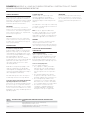
2. Model 2NC jet pumps must be installed
in correct sequence in accord with outline
drawings furnished with the jet pump. Two
stage jet pumps may be assembled directly
with the Y stage connected to the Z stage
as shown in Figure 1, or an elbow may be
located between the Y stage discharge and
the Z stage inlet as shown in Figure 2.
TABLE 2 - RECOMMENDED MINIMUM MOTIVE STEAM LINE SIZES
Model number Line size (in) Model number Line size (in)
L-1H, U-1H ½ 2NC1H, 2NC2H ¾
L-2H, L-3H, U-2H, U-3H ¾ 2NC3H, 2NC4H 1
L-4H, L-5H, U-4H, U-5H 1 2NC5H, 2NC6H, 2NC7H 1¼
L-6H, L-7H, L-8H, U-6H, U-7H, U-8H 1¼ 2NC8H, 2NC9H 1½
L-9H, L-10H, L-11H, U-9H, U-10H, U-11H 1½ 2NC10H, 2NC11H, 2NC12H, 2NC13H 2
L-12H, L-13H, L-14H, U-12H, U-13H, U-14H 2 2NC14H, 2NC15H 2½
L-15H, L-16H, U-15H, U-16H 2½ 2NC16H 3
IMPORTANT
It is very important that model 2NC two stage
ejectors be assembled in the required sequence
as noted previously. First stage ejector suction
connection is to be connected to the vacuum
system and discharge into the second stage
suction connection. Second stage discharges to
atmospheric pressure.
3. Steam must be dry and saturated at not
less than the specified motive steam
pressure. Motive steam pressure is defined
as that pressure at the ejector-steam-inlet
connection as measured with a recently
calibrated, good quality steam gauge. A
small amount of super-heat, 5 to 10° is
preferred. Steam separators and small
super-heaters are recommended as a cure
for wet steam.
4. It is recommended that all single stage
ejector models smaller than L-10H or
U-10H and all two stage ejectors have
a strainer installed in the steam line to
prevent dirt and scale from collecting in
the steam line flow to the nozzle where it
can build up and block the nozzle causing a
malfunction of the ejector.
5. Recommended minimum motive steam line
sizes to the ejector are shown in Table 2
below. These sizes are based on a pressure
drop of 2% per 100 feet of pipe.
Standard ejector steam connections may not be
identical with the steam line size selected, or
shown in Table 2. Correct bushings to suit the
selected pipe size are not supplied and must be
furnished by the user.
All motive steam piping should be insulated and
liquid removed through traps in accordance
with good practice.
FIGURE 1
Motive steam
Connection to
vacuumsystem
Y stage
Motive steam
FIGURE 2
Z stage
Discharge to
atmosphere
Motive steam
Connection to
vacuumsystem
Y stage
Elbow
Z stage
Discharge to
atmosphere
Motive steam

4
6. Steam valves should be installed at each
ejector stage with pressure-tap openings
for attachment of pressure gauges when
required. Pressure readings must be
between the valve and the steam inlet.
7. Discharge piping must permit free flow of
exhaust vapors to prevent back pressure
from exceeding 32 in. (813 mm) hg. absolute
and the ejector discharge connection and
design flow conditions.
WARNING
Ejector exhaust must be piped to atmosphere in
a safe place due to the nature of the gases being
pumped. If exhaust is not piped to a safe place
properly, it could cause severe physical injury or
property damage.
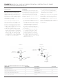
Discharge silencers can be applied by the
user when desired and when sized properly
for pressure drop. If ejectors are discharged
vertically upward to atmosphere, a discharge
trap as shown in Figure 3 should be provided.
Intermediate ejector-stage-discharge piping
must be as short as possible and limited to not
more than one 90°bend. Other arrangements
are possible, but are not recommended without
factory approval of the proposed arrangement
to evaluate pressure loss.
Piping size equal to
ejector discharge size
or larger
Ejector
discharge
Drain line
Motive
steam
Drain leg
FIGURE 3
Discharge to
atmosphere
¼ drain valve
Suction
8. Care must be taken to insure leak-tight
ejector suction piping connections. Ejector
can be connected directly to the system
from which gases and vapors are being
pumped, however, it is recommended that
an isolating valve be provided between the
ejector suction connection and the system.
Operating problems on new processes
will be easier to diagnose and ejector
performance will be checked more easily
if an isolating valve is installed. Leak-tight
gate or butterfly valves are most suitable for
this application.
9. Eliminate or drain possible points of
condensate collection adequately to prevent
freezing.
10. Insulate all steam lines.
11. Do not impose system piping stresses upon
the ejector.
12. Allow clearance for removal of ejector.
5 OPERATION
5.1 Pre-operational check
1. Ensure that all installation procedures have
been completed.
2. Check to determine that all connections are
pressure tight.
5.2 Hydrostatic or vacuum test
1. Take all the precautions necessary to
handle the possibility of leakage during the
test.
2. Hydrostatic pressure test to 100 psig
(690kPaG) or vacuum test and correct any
leakage before proceeding.
5.3 Operating
Note: Steam-jet ejectors are devices using the
energy of the high velocity steam jet as it is
reduced in pressure from steam-inlet pressure
and expanded to suction pressure to entrain
and compress suction gases and vapors from
their inlet-pressure condition to a discharge
pressure that may be 10 or more times greater
than suction-inlet pressure for each individual
stage. Ejector stages are connected in series to
increase total system-compression range and
permit pumping gases and vapors from as low
as 0.25 in. (6.4 mm) hg. absolute pressure to
atmospheric discharge pressure.
1. Single stage ejectors
a. The first step in placing a single stage
model U or L ejector into operation is to
apply steam at the design pressure to the
nozzle.
b. The second step is waiting a period of time
to heat up and clear the steam lines and
ejector of all condensate. At this time,
the ejector should meet its guaranteed
performance.
2. Two stage ejectors
a. The first step in the start up of the two stage
model 2NC ejector system, particularly for
evacuation service, that is, reducing the
pressure within a closed space to some
predetermined value, is to place the Z stage
in operation by admitting design pressure
steam to the Z stage steam inlet.
b. The second step is to admit design steam
pressure to the Y stage steam inlet after the
vacuum system pressure has been reduced
to 10 to 8 inches (254 to 203 mm) of mercury
absolute.
c. After a period of operation sufficiently
long to heat up and clear the steam lines
and ejectors of all condensate, the ejector
system should meet its guaranteed
performance.
PENBERTHY MODELS U, L AND 2NC FABRICATED METAL CONSTRUCTION JET PUMPS
INSTALLATION, OPERATION AND MAINTENANCE INSTRUCTIONS

5
PENBERTHY MODELS U, L AND 2NC FABRICATED METAL CONSTRUCTION JET PUMPS
INSTALLATION, OPERATION AND MAINTENANCE INSTRUCTIONS
6 MAINTENANCE
WARNING
Maintenance should only be undertaken by
qualified, experienced personnel who are
familiar with this equipment and have read and
understood all the instructions in this manual.
DO NOT proceed with any maintenance unless
the jet pump has been relieved of all pressure
or vacuum, has been allowed to reach ambient
temperature and has been drained or purged of
all fluids. Failure to follow these instructions may
cause a sudden release of pressure resulting in
personal injury or property damage.
6.1 Preventative maintenance
The user must create maintenance schedules,
safety manuals and inspection details for each
specific installation of a jet pump.
On all installations the following items should
be evaluated regularly by the user for purposes
of maintenance:
1. Jet pump for corrosion or debris buildup.
2. Piping and fittings for corrosion or debris
build up.
3. All connections for tightness.
4. Units for wear.
5. Strainers for debris build up.
The user must determine an appropriate
maintenance schedule necessary for his or her
own specific application, upon evaluation of
his or her own operating experience. Realistic
maintenance schedules can only be determined
with full knowledge of the services and
application situation involved.
TABLE 3 - TROUBLESHOOTING
Problem Cause Solution
Wet steam 1. Steam temperature not high enough 1. Drain steam inlet lines and install a steam separator in the line or add a steam
superheater to raise steam temperature to about 10°F (-12°C) above saturation
temperature for particularly critical low flow units.
Jet pump not performing up to capacity 1. Low steam pressure 1. Check steam pressure with a recently calibrated steam pressure gauge.
If steam pressure cannot be increased, contact an authorized Penberthy
distributor for assistance
2. Motive steam nozzle becomes plugged 2. Clean out and install a strainer in the motive steam line
3. Air leakage into vacuum system 3. Hydrostatic and vacuum test unit to locate leaks
4. Superheated steam 4. Contact an authorized Penberthy representative for assistance
6.2 System shut down
WARNING
Safety procedures must be taken if hazardous
gases are being discharged from the Z stage
ejector. Failure to follow safety procedures may
cause severe personal injury or property damage.
Shut down of model 2NC ejector systems may
follow the start up procedure in reverse or both
stages may be shut down simultaneously.
When a system is shut down and the pressure
in the vacuum is still below atmospheric
pressure, air will rush back into the process
vacuum system. Since this action may create
a harmful result to the product or may create
a hazardous or explosive condition, it is
recommended that the customer assess this
problem prior to unit installation to protect
against the event of such occurrences.
Installing a manual shut-off valve in the suction
line as close to the ejector as possible will help
prevent such an occurrence.
Another method of preventing the back flow
of air into the vacuum system is to break the
system vacuum by admitting inert gas into the
vacuum vessel.
6.3 Troubleshooting (see table 3)

6
7 REMOVAL - DISASSEMBLY - REASSEMBLY
IMPORTANT
Do not proceed with removal of the jet pump from
connecting piping unless the jet pump has been
relieved of all pressure or vacuum, has been
allowed to reach ambient temperature and has
been drained or purged of all fluids. Failure to
follow these instructions could result in personal
injury or property damage.
To disassemble the unit, first attach a short
piece of pipe to the suction connection as a
handle. Then, grip the nozzle flats and rotate in
a counterclockwise direction.
When ready to reassemble the unit, be sure
the seal face of the nozzle and body are free of
foreign material and raised metal due to nicks.
A non-hardening pipe seal compound may
be applied to the threads to further promote
sealing. Thread the body back on the nozzle
turning in a clockwise direction.
8 DISPOSAL AT END OF USEFUL LIFE
Penberthy jet pumps are used in a variety of
fluid applications. By following the appropriate
federal and industry regulations, the user
must determine the extent of preparation and
treatment the jet pump must incur before its
disposal. A Material Safety Data Sheet (MSDS)
may be required before disposal services accept
certain components.
Metal, glass and polymers should be recycled
whenever possible. Refer to order and
relevant technical data sheet for materials of
construction.
PENBERTHY MODELS U, L AND 2NC FABRICATED METAL CONSTRUCTION JET PUMPS
INSTALLATION, OPERATION AND MAINTENANCE INSTRUCTIONS
9 TELEPHONE ASSISTANCE
If you are having difficulty with your jet pump,
contact your local Penberthy distributor. So that
we may assist you more effectively, please have
as much of the following information available
as possible when you call:
- Model number
- Name of the company from whom you
purchased the jet pump
- Invoice number and date
- Process conditions (pressure, flow rates, tank
shape, etc.)
- A brief description of the problem
- Troubleshooting procedures that failed
If attempts to solve your problem fail, you may
request to return your jet pump to the factory
for intensive testing. You must obtain a Return
Authorization (R.A.) number from Emerson
before returning anything. Failure to do so will
result in the unit being returned to you without
being tested, freight collect. To obtain an R.A.
number, the following information (in addition to
that above) is needed:
- Reason for return
- Person to contact at your company
- 'Ship-to' address
There is a minimum charge for evaluation
of non-warranty units. You will be contacted
before any repairs are initiated should the cost
exceed the minimum charge. If you return a
unit under warranty, but it is not defective, the
minimum charge will apply.

7
61
11
61
82
11
82
11
163
61
82
163
133
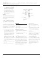
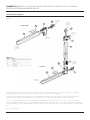
FIGURE 4
Suction
connection
MODEL U AND L
Discharge
connection
Neither Emerson, Emerson Automation Solutions, nor any of their affiliated entities assumes responsibility for the selection, use or maintenance of any product.
Responsibility for proper selection, use, and maintenance of any product remains solely with the purchaser and end user.
Penberthy is a mark owned by one of the companies in the Emerson Automation Solutions business unit of Emerson Electric Co. Emerson Automation Solutions,
Emerson andthe Emerson logo are trademarks and service marks of Emerson Electric Co. All other marks are the property of their respective owners.
The contents of this publication are presented for informational purposes only, and while every effort has been made to ensure their accuracy, they are not to be
construed as warranties or guarantees, express or implied, regarding the products or services described herein or their use or applicability. All sales are governed by
our terms and conditions, which are available upon request. We reserve the right to modify or improve the designs or specifications of such products at any time without
notice.
Emerson.com/FinalControl
10 EXPLODED PARTS DIAGRAM
PARTS LIST
Ref. nr Item
11 Body
61 Nozzle
82 Delivery jet
133 Coupling
163 Nameplate
PENBERTHY MODELS U, L AND 2NC FABRICATED METAL CONSTRUCTION JET PUMPS
INSTALLATION, OPERATION AND MAINTENANCE INSTRUCTIONS
Suction
connection
Steam inlet
connection
'Y' stage
steam inlet
connection
'Z' stage
steam inlet
connection
Discharge
connection
MODEL 2NC
-
 1
1
-
 2
2
-
 3
3
-
 4
4
-
 5
5
-
 6
6
-
 7
7


Penberthy Models U, L, 2NC Fabricated Metal Construction Jet Pumps Owner's manual
- Type
- Owner's manual
Ask a question and I''ll find the answer in the document
Finding information in a document is now easier with AI
Related papers
-
Penberthy Models GL and GH Gas Operated Jet Pumps Owner's manual
-
-
-
-
-
-
-
-
-
Other documents
-
Armstrong Double Duty 6 Installation and Maintenance Manual
-
Everbilt DP550C FAQ
-
 Welch's 2522 User manual
-
SMC ZU Owner's manual
-
Danfoss Multi Ejector Solution, Type CTM 6 HP and LP User guide
-
Danfoss 032F5673 User guide
-
BOMBARDIER Challenger 601-3A CL-600-2B16 Pilot Training Manual
-
Varian HS-20 User manual
-
 Cooper Turbocompressor Turbo Air 3000 User manual
-
Pentair Berkeley 10MS Owner's manual

