Page is loading ...

SE Series
Steam Exchange Humidifier
Installation,
Operation & Maintenance
Guide
Form #07-300
172-0292
IMPORTANT: Read and save this guide for future reference. This
guide to be left with equipment owner.

WARNING:
Improper installation, adjustment, alteration, service or maintenance
can cause injury or property damage. For assistance or additional
information consult a qualified installer or a service agency.

Table Of Contents
GENERAL 1
- RECEIVING & UNPACKING EQUIPMENT................................1
- DELIVERY ................................................1
- GENERAL SPECIFICATIONS ......................................1
- MODEL DESIGNATION .........................................1
MODEL CAPACITY & PHYSICAL DATA 2-7
FLOOR STAND 8
CEILING MOUNTING INSTALLATION 9
TYPICAL SE INSTALLATION DIAGRAM 10
SETC OUTDOOR DIMENSIONS 11
SE INDOOR INSTALLATION 12
- LOCATING AND MOUNTING ......................................12
- PRIMARY WIRING ...........................................12
- ELECTRICAL ..............................................13
- LOW VOLTAGE CONTROL WIRING .................................13
- CONTROL INSTALLATION .......................................16
- PLUMBING ...............................................16
- WATER QUALITY ............................................16
- FILL WATER SUPPLY LINE ......................................16
- DRAIN LINE ...............................................17
- STEAM CONDENSATE OUTLET ....................................17
- AUX DRAIN OUTLET ..........................................17
- STEAM LINES AND CONDENSATE LINE ...............................17
- PRESSURIZED STEAM CONNECTIONS ...............................17
- STEAM SUPPLY PIPING ........................................17
SETC OUTDOOR INSTALLATION 17
- MOUNTING ...............................................17
- PRESSURIZED STEAM SUPPLY ...................................19
- ELECTRICAL INSTALLATION .....................................19
- FILL WATER SUPPLY LINE ......................................19
- DRAIN LINE ...............................................20
- AUX DRAIN ...............................................20
- STEAM LINES..............................................20
OPERATION 20
- WATER MANAGEMENT ........................................20

INSPECTION AND START-UP PROCEDURE 21
- START UP PROCEDURE .......................................21
- FILLING THE SYSTEM .........................................21
- STARTING THE HUMIDIFIER .....................................21
- TAKING OUT OF OPERATION .....................................23
- SE INSPECTION CHECK LIST ...................................24-25
SCALE MANAGEMENT 26
- WATER QUALITY ............................................26
MAINTENANCE 27
- DRAINING THE TANK .........................................27
- CLEANING THE STAINLESS STEEL TANK & FLOAT CHAMBER ..................27
- ADJUSTMENTS/REPLACEMENTS OF COMPONENTS........................28
- SERVICING THE UNIT .........................................28
- TRANSFORMER REPLACEMENT ...................................29
- FILL VALVE REPLACEMENT......................................29
- DRAIN PUMP REPLACEMENT .....................................29
- FILL BOX REPLACEMENT .......................................30
- REMOVAL OF HEAT EXCHANGER ..................................30
- FAULT CONDITIONS ..........................................30
- SETC SETTINGS ..........................................31-32
- SETC LOGIC CONTROL BOARD ...................................33
- KEYPAD DISPLAY MENU STRUCTURE ..............................34-39
- NORTEC TC CONTROLLER ......................................40
- FAULT AND WARNING LIST ......................................50
- MANDATORY MAINTENANCE SCHEDULE ..............................51
- SETC INTERNAL WIRING DIAGRAM .................................52
- SEP INTERNAL WIRING DIAGRAM ..................................53
- SE SERIES SPARE PARTS ....................................54-61

GENERAL
This installation guide has been designed to
provide assistance when installing, mounting, and
sizing a SE Series humidifier. Actual on site
application may vary. Consult NORTEC Technical
Services or your local NORTEC representative.
RECEIVING & UNPACKING EQUIPMENT
1. Check packing slip to ensure ALL material has
been delivered.
2. All material shortages are to be reported to
NORTEC within 48 hours from receipt of
goods. NORTEC assumes no responsibility
for any material shortages beyond this period.
3. Inspect shipping boxes for damage and note
on shipping waybill accordingly.
4. After unpacking, inspect equipment for
damage and if damage is found, notify the
shipper promptly.
5. All NORTEC products are shipped on an
F.O.B. factory basis. Any and all damage,
breakage or loss claims are to be made
directly to the shipping company.
DELIVERY
The standard delivery includes:
1. Steam Exchange humidifier equipped with
desired options.
2. In a bag you will find:
- Manuals.
- Plastic adapter for potable, RO, DI or
softened water connection.
- Steam hose for steam outlet with clamps.
3. The SE Series comes complete with a
telescopic stand mounted inside the unit legs.
Stand cross bracing is shipped with the unit.
(Optional on SE 50).
4. Steam valve, actuator, and wye strainer.
5. Desired accessories ordered.
GENERAL SPECIFICATIONS
The NORTEC SE Series humidifier is a completely
new design based on leading edge technology. The
SE is designed to provide clean atmospheric steam at
an economical price.
-1-
MODEL DESIGNATION
The unit specification label indicates the model of
Steam Exchange humidifier according to the following
chart:
SE 100
PRODUCT LINE
(Steam Exchange Humidifier)
Humidifier size
TC = Total Controller
c/w KEYPAD
P = Economical
TC
50
100
175
250
375
475
675
950
1050
Outdoor
O
C

.
-2-
MODEL CAPACITY & PHYSICAL DATA
SETC/SEP
Operating Steam Pressure
5 psi (34kpa) 7 psi (48kpa) 10 psi (69 kpa) 13 psi (90 kpa) 15 psi (103 kpa)
Lbs/hr (kg/hr)
SE 50 17 (8) 20 (9) 28 (13) 40 (18) 50 (23)
SE 100 33 (15) 41 (19) 58 (26) 80 (36) 100 (45)
SE 175 45 (20) 59 (27) 88 (40) 131 (59) 175 (79)
SE 250 77 (35) 98 (44) 140 (64) 200 (91) 250 (113)
SE 375 105 (48) 136 (62) 200 (91) 294 (133) 375 (170)
SE 475 161 (73) 201 (91) 279 (127) 388 (176) 475 (215)
SE 675 200 (91) 256 (116) 368 (167) 531 (241) 675 (306)
SE 950 386 (175) 463 (210) 609 (276) 800 (363) 950 (431)
SE 1050 446 (202) 529 (240) 682 (309) 880 (399) 1050 (476)
NOTE: Specification subject to change without notice. Rated capacity applies with no blowdown.
Table #1

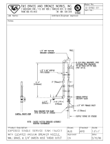
AUXILIARY DRAIN/
CONDENSATE RETURN
TO UNIT 1/2 NPT FEMALE
BOILER STEAM IN
1/2 NPT MALE
STEAM OUTLET
1 3/4" O.D TUBE
SUPPLY WATER
3/4 BSPP MALE OR
1/2 NPT MALE
POWER AND CONTROL
POWER AND CONTROL
BOTTOM PORT
FASTENING POINTS
FOR CEILING MOUNT
7/8 TUBE, DRAIN
3/4 NPT MALE
CONDENSATE OUT
FRONT
RIGHT
4 9/16"
11.6 cm
8 1/4"
21.0 cm
10 5/16"
26.2 cm
1 1/16"
2.8 cm
2 9/16"
6.5 cm
8 3/4"
22.3 cm
7/8"
2.3 cm
1 3/8"
3.5 cm
14 1/2"
36.9 cm
12 13/16"
32.6 cm
1 1/2"
3.8 cm
2 1/4"
5.8 cm
1 7/16"
3.7 cm
25 5/8"
65.1 cm
20 5/8"
52.4 cm
18 3/8"
46.7 cm
1"
2.6 cm
8"
20.3 cm
16 3/4"
42.6 cm
19 9/16"
49.7 cm
1 13/16"
46.3mm
2 11/16"
6.9 cm
1 9/16"
4.0 cm
Physical Data
SETC / SEP 50
3/27/06
TOP 0” 0 cm
LEFT 0” 0 cm
RIGHT 30" 76 cm
REAR 0” 0 cm
FRONT 30" 76 cm
BOTTOM 0” 0 cm
SERVICE CLEARANCE
TECHNICAL DATA
Max. Rated Steam 56 lb/hr 25.4 kg/hr
Nominal @ 5 psi 3-17 lb/hr 1.4-7.7 kg/hr
Nominal @ 10 psi 6-28 lb/hr 2.7- 12.7 kg/hr
Nominal @ 15 psi 10-50 lb/hr 4.5-22.6 kg/hr
Steam Valve CV
Supply Water Con.
Drain Water Connection
Aux. Drain Con.
Pressure Steam In
Steam Cond. Out
Atm. Steam Out
Weight Empty 125 lb 57 kg
Weight Full 180 lb 82 kg
SE 50
2.2
1 x 1.75 OD (4.5 cm)
¾” NPT male
½”NPTor¾”BSPPmale
0.825” (2.1 cm) tube
½” NPT female
½” NPT male
-3-

Physical Data
SETC 100 - 175
5/4/07
Technical data
Max.Rated Steam 105 lb/hr 48 kg/hr 180 lb/hr 82 kg/hr
Nominal @ 5psi 5-33 lb/hr 2-15 kg/hr 7-45 lb/hr 3-20 kg/hr
Nominal @10psi 9-58 lb/hr 4-26 kg/hr 13-88 lb/hr 6-40 kg/hr
Nominal @15psi 15-100 lb/hr 7-45 kg/hr 26-175 lb/hr 12-79 kg/hr
Steam Valve CV
Supply water con.
Drain water con.
Aux. drain con.
Pressure steam in.
Steam Cond. Out.
Atm. Steam Out. 1 x 1.75” OD 1 x 4.4 cm OD 1 x 3.00” OD 1 x 7.62cm OD
Weight Empty 267 lb 121 kg 267 lb 121kg
Weight Full 423 lb 192 kg 423 lb 192 kg
2.8
0.5” NPT
0.5” NPT female
7.5
0.5” NPT
.75" NPT
0.5” NPT
0.75” O.D. tube
0.5” NPT female
0.5” NPT
.75" NPT
0.75” O.D. tube
SE 100 SE 175
TOP 36” 91 cm
LEFT 0” 0 cm
RIGHT 30" 76 cm
REAR 0” 0 cm
FRONT 30" 76 cm
BOTTOM 0” 0 cm
SERVICE CLEARANCE
PRESSURE
STEAM INLET
WATER INLET
DRAIN
STEAM
CONDENSATE OUTLET
AUX. DRAIN
TOP
FRONT
RIGHT SIDE
POWER SUPPLY
STEAM OUTLET
CONTROL SIGNAL
CONTROL PANEL
20.8"
( 53cm )
13.9"
( 35.2cm )
5.5"
( 13.9cm )
44.5"
( 113.2cm )
31.6"
( 80.3cm )
9.7"
( 24.6cm )
16.1"
( 40.8cm )
7.4"
( 18.92cm )
10.3"
( 26.2cm )
1.0"
( 2.5cm )
2.5"
( 6.4cm )
6.8"
( 17.18cm )
1.9"
( 4.83cm )
3.7"
( 9.47cm )
2.0"
( 5.1cm )
1.0"
( 2.5cm )
4.1"
( 10.3cm )
4.0"
( 10.2cm )
21.0"
( 53.3cm )
40.2"
( 102.2cm )
3.5"
( 9cm )
1.5"
( 3.9cm )
-4-

Physical Data
SETC 250 - 375
5/4/07
Technical data
Max.Rated Steam 255 lb/hr 115 kg/hr 380 lb/hr 172 kg/hr
Nominal @ 5psi 11-77 lb/hr 5-35 kg/hr 15-105 lb/hr 7-47 kg/hr
Nominal @10psi 21-140 lb/hr 10-64 kg/hr 30-200 lb/hr 14-91 kg/hr
Nominal @15psi 37-250 lb/hr 17-114 kg/hr 56-375 lb/hr 25-170 kg/hr
Steam Valve
Supply water con.
Drain water con.
Aux. drain con.
Pressure steam in.
Steam Cond. Out.
Atm. Steam Out. 1 x 3” OD 1 x 7.62 cm OD 1 x 4” OD 1 x 10.2cm OD
Weight Empty 355 lb 161 kg 355 lb 161 kg
Weight Full 599 lb 272 kg 599 lb 272 kg
SE 250 SE 375
0.5” NPT 0.5” NPT
12 28
0.75” O.D. tube 0.75” O.D. tube
0.5” NPT female 0.5” NPT female
1.0” NPT 1” NPT
.75” NPT .75” NPT
TOP 36” 91 cm
LEFT 0” 0 cm
RIGHT 30" 76 cm
REAR 0” 0 cm
FRONT 30" 76 cm
BOTTOM 0” 0 cm
SERVICE CLEARANCE
PRESSURE
STEAM INLET
STEAM
CONDENSATE OUTLET
9.7"
( 24.6cm )
22.4"
( 56.8cm )
1.9"
( 4.8cm )
1.0"
( 2.6cm )
2.5"
( 6.4cm )
3.7"
( 9.5cm )
7.4"
( 18.9cm )
2.0"
( 5.1cm )
1.0"
( 2.5cm )
4.1"
( 10.3cm )
6.8"
( 17.2cm )
CONTROL PANEL
POWER SUPPLY
44.6"
( 113.3cm )
31.6"
( 80.3cm )
4.0"
( 10.2cm )
21.0"
( 53.3cm )
40.2"
( 102.2cm )
27.2"
( 69cm )
13.9"
( 35.2cm )
5.5"
( 13.9cm )
3.5"
( 9cm )
1.5"
( 3.9cm )
STEAM OUTLET
CONTROL SIGNAL
WATER INLET
DRAIN
AUX. DRAIN
TOP
FRONT
RIGHT SIDE
10.3"
( 26.2cm )
-5-

Physical Data
SETC 475 - 675
5/4/07
Technical data
Max.Rated Steam 480 lb/hr 217 kg/hr 680 lb/hr 308 kg/hr
Nominal @ 5psi 24-161 lb/hr 11-73 kg/hr 30-200 lb/hr 14-91 kg/hr
Nominal @10psi 42-279 lb/hr 19-127kg/hr 55-368 lb/hr 25-167 kg/hr
Nominal @15psi 71-475 lb/hr 32-215 kg/hr 101-675 lb/hr 46-306 kg/hr
Steam Valve CV
Supply water con.
Drain water con.
Aux. drain con.
Pressure steam in.
Steam Cond. Out.
Atm. Steam Out. 1 x 4” OD 1 x 10.16cm OD 1 x 4” OD 1 x 10.16cm OD
Weight Empty 529 lb 240 kg 529 lb 240 kg
Weight Full 992 lb 450 kg 992 lb 450 kg
SE 475 SE 675
0.5” NPT 0.5” NPT
20 28
0.75” O.D. tube 0.75” O.D. tube
0.5” NPT female 0.5” NPT female
1.25 ” NPT 1.5” NPT
1.0” NPT 1.0” NPT
TOP 36” 91 cm
LEFT 30" 76 cm
RIGHT 30" 76 cm
REAR 0” 0 cm
FRONT 30" 76 cm
BOTTOM 0” 0 cm
SERVICE CLEARANCE
3.7"
( 9.5cm )
7.4"
( 18.9cm )
10.3"
( 26.2cm )
1.9"
( 4.8cm )
1.0"
( 2.5cm )
2.5"
( 6.4cm )
6.8"
( 17.2cm )
4.1"
( 10.3cm )
2.0"
( 5.1cm )
1.0"
( 2.5cm )
9.7"
( 24.6cm )
21.9"
( 55.5cm )
38.0"
( 96.4cm )
31.6"
( 80.3cm )
4.0"
( 10.2cm )
21.0"
( 53.3cm )
40.2"
( 102.2cm )
13.7"
( 34.9cm )
5.5"
( 13.9cm )
3.5"
( 9cm )
1.5"
( 3.9cm )
42.7"
( 108.6cm )
CONTROL SIGNAL
CONTROL PANEL
POWER SUPPLY
PRESSURE
STEAM INLET
WATER INLET
DRAIN
STEAM
CONDENSATE OUTLET
AUX. DRAIN
STEAM OUTLET
TOP
FRONT
RIGHT SIDE
-6-

Technical data
Max.Rated Steam 960 lb/hr 435 kg/hr 1070 lb/hr 485 kg/hr
Nominal @ 5psi 58-386 lb/hr 26-175 kg/hr 67-446 lb/hr 30-202 kg/hr
Nominal @10psi 91-609 lb/hr 41-276 kg/hr 102-682 lb/hr 46-309 kg/hr
Nominal @15psi 142-950 lb/hr 64-430 kg/hr 158-1050 lb/hr 72-476 kg/hr
Steam Valve CV
Supply water con.
Drain water con.
Aux. drain con.
Pressure steam in.
Steam Cond. Out.
Atm. Steam Out. 2 x 4” OD 2 x 10.16cm OD 2 x 4” OD 2 x 10.16cm OD
Weight Empty 703 lb 319 kg 703 lb 319 kg
Weight Full 1384 lb 628 kg 1384 lb 628 kg
1.25” NPT 1.25” NPT
0.75” O.D. tube 0.75” O.D. tube
0.5” NPT female 0.5” NPT female
2.0” NPT 2.5” NPT
SE 950 SE 1050
0.5” NPT 0.5” NPT
40 65
TOP 36” 91 cm
LEFT 30" 76 cm
RIGHT 30" 76 cm
REAR 0” 0 cm
FRONT 30" 76 cm
BOTTOM 0” 0 cm
SERVICE CLEARANCE
Physical Data
SETC 950 - 1050
5/4/07
1.0"
( 2.5cm )
2.5"
( 6.4cm )
7.4"
( 18.9cm )
10.3"
( 26.2cm )
4.1"
( 10.3cm )
6.8"
( 17.2cm )
2.0"
( 5.1cm )
1.0"
( 2.5cm )
9.7"
( 24.6cm )
29.7"
( 75.3cm )
53.6"
( 136.1cm )
31.6"
( 80.3cm )
4.0"
( 10.2cm )
21.0"
( 53.3cm )
40.2"
( 102.2cm )
9.9"
( 25cm )
39.5"
( 100.2cm )
8.0"
( 20.3cm )
58.3"
( 148.2cm )
5.5"
( 13.9cm )
5.3"
( 13.6cm )
3.5"
( 9cm )
STEAM
OUTLETS
CONTROL SIGNAL
PRESSURE STEAM INLET
CONTROL PANEL
POWER SUPPLY
AUX. DRAIN
STEAM CONDENSATE
OUTLET
WATER INLET
DRAIN
1.5"
( 3.9cm )
RIGHT SIDE
FRONT
TOP
-7-

-8-

-9-
SECURE RODS
TO STABLE STRUCTURE
UPPER BRACING BRACKET
RECOMMENDED
SLIDE UNIT ONTO RODS
THROUGH HOLES PROVIDED
IF USING FACTORY HARDWARE, RODS CAN
ONLY EXTEND 1" PAST THE BOTTOM OF THE CABINET
SLIDE FACTORY SUPPLIED
BOTTOM BRACKETS IN PLACE
SECURE BRACKETS TO RODS. PROPER INSTALLATION MEANS MUST BE
USED TO ENSURE THAT THE ASSEMBLY DOES NOT DETACH
IF USING FACTORY DRIP PAN, FASTENING HARDWARE MUST BE CONCEALED
WITHIN THE PROFILE OF THE BOTTOM BRACKETS
ATTACH DRIP PAN. SECURE TO BOTTOM BRACKETS VIA END SCREW ATTACHMENT
1/2 NPT PLUMBING OR EQUIVALENT IS RECOMMENDED
TERMINATE AT DRAIN
DO NOT DRAIN UNIT INTO DRIP PAN. DO NOT ROUTE ANY OTHER FLUID TO DRIP PAN.
DRIP PAN IS NOT A STRUCTURAL MEMBER AND CANNOT BE USED TO SUPPORT OTHER ELEMENTS
NOTES:
1. UNIT WEIGHT WITH WATER = 180 LB. THIS DOES NOT INCLUDE THE ADDITIONAL PLUMBING NEEDED
FOR CONNECTION. TOTAL WEIGHT MUST BE DETERMINED BY OTHERS.
2. STRUCTURAL CONSIDERATIONS ARE THE RESPONSIBILITY OF OTHERS.
3. PROPER MOUNTING MEANS, SUCH AS; THE SECURING OF FASTENERS OR OTHER JOINTS, IS THE
RESPONSIBILITY OF OTHERS.
4. UNIT CANNOT BE USED AS A STRUCTURAL MEMBER. NO OTHER COMPONENTS MAY BE ATTACHED TO
IT.
5. SERVICE ACCESS IS REQUIRED AT THE FRONT AND RIGHT SIDE OF THE UNIT. A MINIMUM OF
30” (76 cm) CLEARANCE IS NEEDED.
6. SIZES AND FEATURE LOCATIONS ARE TO BE DERIVED FROM THE UNIT DIMENSIONAL DRAWINGS OR
BY CONSULTING THE FACTORY.
THREADED ROD
3/8" OR METRIC M10
SE 50
Ceiling Mounting Installation (Optional)
3/27/06

-10-
Typical SE Installation
SAM-e (Short Absoption Manifold)
Can be installed in the Horizontal
duct or vertical Duct or a AHU.
Reference SAM-e Installtion
Manual
Condensate Return
to drain or sump pump
Primary wire and
disconnect (By Others)
Standard
Telescopic
Stand
(Option by
Nortec)
1/2" NPT Supply water
connection. (Manual shut-off
valve by Others)
3/4" O.D. Drain connection
to funnel drain or sump pump
1/2" NPT Aux. Drain, Optional
Plugged at factory
(Shut-off valve by Others)
Funnel with 1" air gap
supplied by others
Controls (By Nortec or by Others)
Steam Valve and Actuator must be located 6" max.
from the SE humidifier.
Inlet located on top of unit for SE models 475 to 1050.
Valve and Actuator must be installed horizontally.
Refer to the Invensys installation manual for details.
12"
2"
1. This drawing is for reference only. Installation
must conform to all local codes.
2. Refer to physical data drawings for dimensions.
6"Min
6" min., P-Trap must be 2" more than
duct static pressure
3/4" NPT Condensate
Return
Copper or S.S.
pipe - 1" Insulation
Recommanded
Stainless Steel
Steam Header
Galvanized Mounting Frame
Optional
Typical SE Installation
Stainless steel
steam tubes
Open floor drain must be properly sized
and rated for maximum temperature requirements.
Duct or AHU
Short-Absorption Manifold (SAM-e)
6" Long hose cuff and 2 gear
clamps for steam line connection.
(by Nortec)
Union
(by Others)
6" Long hose cuff for 1.75" dia. tubing
4" long hose cuff for 3" & 4" dia. tubing
and 2 gear clamps for steam line connection.
(By Nortec)
Steam condensate drain.
Return to nonpressurized system,
by gravity only
Pressurized steam connection from Boiler
Max. 15 psi
Min. 5 psi
Water supply
30 to 80 psig
Drain water cooler and
F & T Steam trap(s)
Located inside unit. Installed
at Nortec
Steam trap (By Nortec or by Others)
Return to nonpressurized system,
by gravity only
Wye strainer (By Nortec)
6"Min

-11-
NEMA RATED
JUNCTION BOX
(By Others)
CLEARANCE
ENVELOPE
A
30”
(76.2 cm)
10”
(258mm)
*Required for
SETC Outdoor
475-1050
49.7”
(126.2 cm)
12”
(30.5 cm)
40”
(101.6 cm)
54.3”
(138 cm)
RIGHT
Steam
Outlet(s)
TOP
FRONT
RIGHT
BACK
LEFT
*Cleaning Port for
SETC Outdoor 475-1050
Power and
Controls
Vent
Hood
FRONT
Cleaning
Port
in cm lbs kg lbs kg in cm NPT
SETC Outdoor 100
1x1.75 1x4.4
SETC Outdoor 175
1x3 1x7.6
SETC Outdoor 250
1x3 1x7.6
SETC Outdoor 375
1x4 1x10.2
SETC Outdoor 475
SETC Outdoor 675
SETC Outdoor 950
SETC Outdoor 1050
1.25
Model
1x4 1x10.2
Steam Condensate
Outlet
0.75
0.75
1
2.5
2x4 2x10.2
1.5
1.25
1.5
2
NPT
0.5
0.75
1
Pressure Steam
Inlet
A
Shipped
Weight
Operating
Weight
Steam Outlet
(O.D.)
192
272
450
628
423
599
992
1384
121
161
240
319
267
355
529
703
27.9
21.5 54.6
70.8
59.1 150
11143.5
SETC Outdoor Dimensions
1/26/04

SE INDOOR INSTALLATION
LOCATING AND MOUNTING
SE Series humidifiers are designed to mount on
an SE Stand (Included with all models) or floor. The
clearance dimensions shown in this manual are for
reference only and are the minimum required for
maintenance of the humidifier. Local and National
Codes should be consulted prior to final location and
installation of the humidifier. NORTEC cannot accept
responsibility for installation code violations.
·
Figure #1 shows the locations of all required
connections to the Steam Exchange Humidifier.
Careful consideration should be given to all of
these connections when choosing a location for
the humidifier.
·
For front and side clearance requirements (for
access during installation, maintenance and
troubleshooting), refer to pages3-6.
· DO NOT locate humidifier any further than
absolutely necessary from steam distributor
location. Net output will be reduced as a result of
heat loss through steam line. Also, increased
static pressure (over 12" W.C.) will result in hot
water going down the drain. Consult factory if this
situation occurs.
· Where possible, mount humidifier at a height
convenient for servicing.
·
Make sure the humidifier is mounted level.
·
Ambient temperature location for humidifier:
41ºF - 104ºF (5ºC - 40ºC).
·
Relative humidity location for humidifiers:
5% rh - 80% rh.
·
DO NOT mount humidifier on hot surfaces.
·
DO NOT mount humidifiers in an area where
freezing may occur.
·
If humidifiers are mounted on roof, a properly
ventilated, temperature controlled, (above
freezing), weatherproof model should be used.
Consult your local representative for more
information on NORTEC’s SETC Outdoor model.
·
DO NOT mount humidifiers on vibrating surface.
Consult factory.
·
The humidifier shall not be installed directly on
carpeting, tile or other combustible material other
than wood flooring.
· Some insulating materials may be combustible.
Prior to installing this appliance examine the area
for insulating material. If this appliance is
installed in an insulated space, it must be kept
free and clear of insulating materials. If insulation
is added after the appliance is installed, it will be
necessary to examine the area again.
PRIMARY WIRING
All work concerning the electrical installation
must be performed by qualified personnel.
-12-
NOTE: VoltageAtTerminal Block Must Be InAccordance With Spec. Label.
All WiringTo Be InAccordance With Existing NationalAnd Local Electrical Codes.
L1
Ground
Ground Wire
Ground
Leg
Note:
- 120V/ 1 phase Supply.
- 120V/1phase between hotand neutral.
- 240V/1phase between two120V/1ph supply.
Neutral
E
X
T
I
N
T
120V/1ph
L1
Neutra
l
2 Pole
Terminal
Block
Figure #1
Primary Wiring to Humidifier

ELECTRICAL
WARNING: The electrical parts inside the
humidifier are very sensitive to electrostatic discharge.
Appropriate measures against electrostatic discharge
(ESD protection) must be taken when carrying out
installation work.
·
The humidifier should only be connected to
primary power (main power) after all installation
work has been completed.
·
An external disconnect switch(by others) must be
installed close to the unit to allow for power
interruption during servicing and/or maintenance.
·
Humidifiers require field wiring to primary voltage
terminal blocks. Power requirement must be
110-120/1/60Vac, 15A or 20 A for SETC Outdoor
950 &1050 separately fused circuit, single phase.
Wiring can be fed through a 7/8" hole on the
bottom or the top of the control compartment.
· When installed, the appliance must be electrically
grounded in accordance with local codes or, in
the absence of local codes, with the National
Electrical Code, ANSI/NFPA 70, and/or the CSA
C22.1 Electrical Code, if an external electrical
source is utilized.
· External wiring sizes must be in accordance with
NEC and/or CEC and existing local electrical
codes and by-laws.
LOW VOLTAGE CONTROL WIRING
(See Pages 11, 12 , and 15 for details)
All SE models require at least one type of input
control signal for unit operation. Refer to the sections
below that detail the types of controls that can be used
with each model.
Low voltage control terminal strips are provided in
the electrical compartment. Refer to the specific
control wiring diagram supplied with each unit.
Field wiring from humidistat to humidifier and
between devices should be shielded 18 AWG or
heavier and kept as short as possible.
Controls are available from NORTEC as
accessories and can be ordered with the humidifier.
Controls by others may also be used as long as they
meet the criteria noted below. The following is a
summary of the common types of controls that may be
used with NORTEC SE Humidifiers.
A – Wall or Duct Mounted Control On/Off
Humidistat: Wired to make on drop in humidity, break
on rise to set point. Set to desired RH. Can be a
make/break set of contacts from a Building
Management System.
B – Duct Mounted Safety High Limit On/Off
Humidistat: Wired to make on drop in humidity, break
on rise to safety set point. Set to approximately 85%
RH as a safety to prevent saturation and wetting in the
duct. Highly recommended for ducted applications.
C – Duct Mounted Safety Air Proving On/Off
Switch: Wired to make when sensing air flow, break
when no air flow. Used as a safety to prevent
saturation when there is no air flow. Highly
recommended for ducted applications.
D – Wall or Duct Mounted Modulating Humidistat:
Provides a modulating signal to the unit that
represents the output (up to 100%) required from the
humidifier. Signal type can be changed in the field via
dip switch settings on the logic control board. Refer to
page 31-33 for settings.
The SETC can accept a single or dual control
signal. The SEP can only accept a single control
signal:
SETC SEP
0-20 mA
4-20 mA 4-20 mA
0-10 VDC 0-10 VDC
2-10 VDC
0-5 VDC
1-5 VDC
ON/OFF ON/OFF
The unit must be ordered from the factory for the
desired signal type and number of channels. If no
signal type was specified, ON/OFF control signal will
be set as default. When configured for 2-channel
modulation the humidifier will generate steam only if
both channels indicate a demand (see D). If both
channels are demanding steam the humidifier will
satisfy the lower demand signal.
-13-

SETC SERIES
EXTERNAL CONTROLS WIRING CONNECTIONS
LOW VOLTAGE TERMINAL STRIP
WARNING: Failure to wire the controller in accordance with the wiring diagram that was supplied
with the unit could permanently damage the SETC board. Such errors will void the unit warranty.
NOTE: This is a wiring diagram only. For specific wiring instructions, it is necessary to refer
to the wiring diagram which is supplied with each unit.
generic
Low Voltage Terminal Strip
1 & 2: Wire all on/off controls and safeties between these two terminals. If not used, jumper1&2forthe
unit to operate.
4: Modulating input to humidifier “A”.
5: Modulating input to humidifier “B”.
6: 10 Vdc output (20 mA max.) Can be used to simulate demand to unit..
8: When 24 Vac input received, the unit will initialize a full tank blowdown.
9: Safety interrupt (24 Vac).
10 & 11: Remote indication connection for humidifier “on” status indication.
12 & 13: Remote indication connection for humidifier “active” status.
14 & 15: Remote indication connection for service required indication.
16,17 & 18: Remote indication connection for fault indication.
19, 20 & 21: Modulating output and 24VAC power to actuator
1
2
3
4
6
5
7
8
9
10
1211
EXTERNAL
INTERNAL
EXTERNAL
INTERNAL
Security Loop
Modulation Input Signal “A"
Modulation Input Signal “B”
10 Vdc output (20 mA max.)
Full Tank Blow Down (FTBD)
enable (24 Vac)
Safety Interrupt (24 Vac)
NOTE: If no On/Off Control is used then a field jumper
must be connected across terminals 1 and 2 in order
for the humidifier to operate.
14
1815
16
17
13
COM
COM
COM
COM
N.O.
N.O.
N.O.
N.C.
N.O.
Humidifier “ON”
Humidifier “ACTIVE”
Humidifier “SERVICE”
Humidifier “FAULT”
19 20 21
24V (Hot)
Common
Signal
Actuator
SETC SERIES
External Controls Wiring Connections
09/16/2004
-14-

SEP SERIES
External Controls Wiring Connections
09/16/2004
SEP SERIES
EXTERNAL CONTROLS WIRING CONNECTIONS
LOW VOLTAGE TERMINAL STRIP
WARNING: Failure to wire the controller in accordance with the wiring diagram that was supplied
with the unit could permanently damage the SEP board. Such errors will void the unit warranty.
NOTE: This is a wiring diagram only. For specific wiring instructions, it is necessary to refer
to the wiring diagram which is supplied with each unit.
generic
Low Voltage Terminal Strip
1 & 2: Wire all on/off controls and safeties between these two terminals. If not used, jumper1&2forthe
unit to operate.
4: Modulating input to humidifier
5,6&7: Modulating output and 24VAC power to actuator
8, 9 & 10: Remote indication connection for fault indication.
1
2
3
4
6
5
7
8
9
10
1211
EXTERNAL
INTERNAL
EXTERNAL
INTERNAL
Security Loop
Modulation Input Signal
NOTE: If no On/Off Control is used then a field jumper
must be connected across terminals 1 and 2 in order
for the humidifier to operate.
COM
N.C.
N.O.
Humidifier “FAULT”
24V (Hot)
Common
Signal
Actuator
-15-

CONTROL INSTALLATION
·
Mount any wall humidistat (control or high limit)
over standard electrical box at height similar to
typical thermostat. Any wall humidistat should be
in location representative of overall space being
humidified and not in path of blower pack or air
supply grille. Do not mount on an outside wall
where temperature fluctuations can affect control
response. (Windows, sky lights, sinks, coffee
machines, etc.)
·
Mount duct humidistat in location representative
of overall air humidity, usually in return duct. Do
not mount it directly in front of steam distributor or
in turbulent or mixing zone. Mount humidistat
where air’s humidity and temperature are uniform
and representative of spaces being humidified.
·
Mount duct high limit humidistat downstream of
steam distributors far enough that, under normal
humidity and air flow conditions, steam will have
been fully absorbed (typically at least 10 feet). It
must be located to sense high humidity only
when uniform and representative air is
over-humidified or approaching saturation.
· Mount duct air-proving switch so that it is able to
sense air flow or lack thereof it. Wire it to make
when air flow is sensed and break when air flow
fails.
· Check operation of all on/off controls before
starting humidifier.
·
Calibration of controls (on/off or modulation) in
the field may be necessary due to shipping and
handling. Verify humidistat accuracy before
commissioning system.
PLUMBING
NOTE: All water supply and drain line
connections should be installed in accordance with
local plumbing codes.
WATER QUALITY
·
The humidifier is intended to operate on cold
water.
·
DO NOT use a hot water source to supply the
humidifier. Minerals will adhere more easily to
surfaces and the fill valve’s small flow regulating
orifice could become plugged.
·
Consider using a water softener. Longer
operating times between tank cleaning will be
achieved with softened water.
·
Reverse osmosis (RO) water can provide very
long periods before cleaning is required since it is
cleaner than softened water. Deionized (DI)
water may be used with all models with the
stainless steel water supply option. Consult your
NORTEC representative for a quote on a water
treatment system.
FILL WATER SUPPLY LINE
·
Each unit is supplied with an adapter for the fill
valve (½”NPT ). The SE 50-675 has a fill rate of
10l/min (2.6 gpm) and the SE 950-1050 of
17l/min (4.5gpm). Size of piping is a minimum ½”
copper, recommend ¾” up to within 4 feet of unit.
·
Standard fill valves are sized for water pressure
ranging from 30 to 80 psig (ideally 55 to 60 psig).
For other pressures, consult factory. This
pressure should be measured at the humidifier if
the water pressure is suspect.
· It is recommended to have a faucet installed
close to the humidifier to allow quick filling of the
system on initial start up. This can also be very
useful for mandatory cleaning of the unit.
· ALWAYS supply and install a shut-off valve and
union in the water supply line dedicated to the
humidifier to facilitate servicing.
-16-
Figure #2
Installation
/