
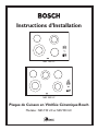
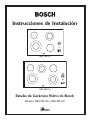
Installation Instructions
Bosch Ceramic Glass Cooktops
Models: NES 730 UC, NES 930 UC
NES 730 UC
NES 930 UC

Installation Instructions Models: NES 730, NES 930
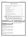
Table of Contents
NOTE: The blocked letters, such as A, shown below, refer to illustrations on
Pages 2 & 4. Match these to the related text pages.
Overall Dimensions A..................................................................................................2
Power Supply B .............................................................................................................2
Cabinet Preparation and Clearances C .............................................................. 2, 3
Junction Box Location D .............................................................................................2
Countertop Cutout Dimensions E ..........................................................................2
Installing the Cooktop F ......................................................................................... 3-4
Secure Cooktop to Countertop G ...................................................................... 3-4
Solid Surface Countertop Installations H and I ................................................ 4-5
Electrical Connection ...................................................................................................5
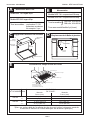
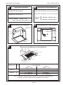
OVERALL DIMENSIONS
A
See Illustration A, Page 2. These dimensions are
overall.
POWER SUPPLY B
ELECTRICAL POWER CONNECTION
FOR COOKTOP
Power Supply is dual rated: 240 Volts or 208 Volts,
4 wire, 60 Hz, with the following circuit breaker
requirements:
Model NES 730 at 30 Amps; Model
NES 930 at 40 Amps
Connect only to a 4-wire 120/240 or 120/208 volt
ac system. The neutral is required for the operation
of this appliance and an independent ground is
required.
Install a junction box (not supplied), below the
counter top within 3 feet of flexible conduit
(supplied) located at the left rear corner of the
cooktop rough-in box.
IMPORTANT: Save these instructions for Local Electrical Inspector’s use.
INSTALLER: Please leave these Installation Instructions with this unit for the owner.
OWNER: Please retain these instructions for future reference.
READ AND SAVE THESE INSTRUCTIONS
JUNCTION BOX LOCATION D
Plan the installation of the unit so that the location
of the junction box is within 3 feet of the left rear
of the cooktop bottom. It must be accessible
from the front of the cabinet.
PAGE 1

Installation Instructions
Models: NES 730, NES 930
NES 730
B19
-7
/8"
/
(505 mm) 20"
/
(508 mm)
C28
-3
/4"
/
(731 mm) 28
-7
/8"
/
(734 mm)
NES 930 B 19
-7
/8"
/
(505 mm) 20"
/
(508 mm)
C34
-3
/4"
/
(883 mm) 34
-7
/8"
/
(886 mm)
PAGE 2
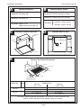
A B
Overall Dimensions
Model NES 730: Width 30"
Model NES 930: Width 36"
All Models: Depth 21-1/8"
Height above countertop: 1/4"
Model NES 730: 30 Amp circuit breaker
Model NES 930: 40 Amp circuit breaker
All Models
}
240 Volt, 4 Wire, 60 Hz
208 Volt, 4 Wire, 60 Hz
Required Power Supply
Cabinet Bottom
(Unprotected)
Building Back
Wall
Building Side
Wall
Cooking Surface
30" Min.
(762 mm)
"J" Box
12" APPROXIMATE
Conduit
(Approx. 3 feet)
*For solid surface countertop installations, use maximum cutout dimensions and
consult surface manufacturer for specific cutting instructions.
CUTOUT
MODEL NO. DIM. DIMENSIONS*
Minimum Maximum
Inches / (mm) Inches / (mm)
C
Minimum Cabinet Clearances
D
Junction Box Location
E
Counter Top Cutout Dimensions
B
1" Flat Area
1" Flat Area
1" Flat Area
C
30" Minumum
2-1/2"
Setback Distance
(
from front edge of counter-
top to front edge of cutout.)
1-3/4" Flat Area

Installation Instructions Models: NES 730, NES 930
PAGE 3
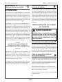
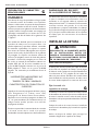
CABINET PREPARATION AND
CLEARANCES
CAUTION
To eliminate the risk of burns or fire by reaching
over heated surface units, cabinet storage space
located above the surface units should be
avoided. If cabinet storage is to be provided, the
risk can be reduced by installing a range hood
that projects horizontally a minimum of 5 in. (127
mm) beyond the bottom of the cabinets. See C,
Page 2.
This unit is designed for installation in the counter top
with zero clearance to adjacent walls and projecting
surfaces constructed of combustible materials. A 30-
inch minimum clearance is required between the top
of the cooktop and the bottom of an unprotected
cabinet. A 24-inch minimum distance is necessary when
the bottom of the wood or metal cabinet is protected
by not less than 1/4 inch of a flame retardant material
covered with not less than No. 28 MSG sheet steel,
0.015-inch (0.4 mm) thick stainless steel, 0.024-inch
(0.6 mm) aluminum, or 0.020-inch (0.5 mm) thick
copper. Flame retardant materials bear the mark:
UNDERWRITERS LABORATORIES INC.
CLASSIFIED
MINERAL AND FIBER BOARDS
SURFACE BURNING CHARACTERISTICS
Followed by the flame spread and smoke ratings, these
designations are shown as “FHC (Flame Spread)/
(Smoke Developed).” Materials with “O” flame spread
ratings are flame retardant. Local codes may allow other
flame spread ratings.
The minimum horizontal clearance from the sides and
back edge of the cooktop to the adjacent vertical
combustible walls is zero inches.
COUNTERTOP CUTOUT
DIMENSIONS
The cutout dimensions depend upon whether the
installation is for replacement, new construction, or
installation in a solid surface countertop material, such
as Surel™, Corian
®
etc. These materials require larger
cutouts, use of heat reflective tape and rounded
corners. Drawings G and H provide some guidelines
only (see Page 4 and 5). Always consult the countertop
manufacturer for specific installation instructions.
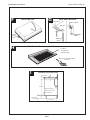
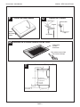
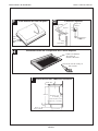
INSTALLING THE COOKTOP
WARNING:
TO AVOID ELECTRICAL SHOCK HAZARD,
BEFORE INSTALLING THE COOKTOP,
SWITCH POWER OFF AT THE SERVICE
PANEL AND LOCK THE PANEL TO
PREVENT THE POWER FROM BEING
SWITCHED ON ACCIDENTALLY.
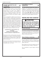
Seal with foam tape
A foam tape is provided to seal the cooktop edges to
the countertop (see page 4). Turn cooktop upside down
and apply tape approximately 1/16” from the glass
edges. Use tape around the entire glass perimeter cut
off excess where tape ends butt.
Secure Cooktop to countertop
The cooktop should be secured to the countertop
using the hold-down brackets provided. Prior to
inserting cooktop into cutout, turn cooktop upside
down and attach brackets to the burner box using the
washers and screws.
Place cooktop into cutout. Insert clamping screws into
the brackets and secure cooktop to countertop.
Use a wood block to protect fragile countertop
materials.
!
F
G
E
C

Installation Instructions
Models: NES 730, NES 930
PAGE 4
Foam
Tap e
Seal
Foam Tape Seal
Burner Box
Bracket
Wood block
Adjusting
Screw
Hold Down Brackets
Location
of aluminum
reflective tape
Tape top and vertical sides
of cutout
Solid Surface Countertop Installation
Installing Over An Oven
I
H
F
G
3-5/8" Min.
27-3/8"
4" Nominal
Toe Space
3/4"
2 x 4 Supports
Cooktop Conduit
Exposed edge must
be a finish-cut

Installation Instructions Models: NES 730, NES 930
PAGE 5
Solid Surface Countertops H
Always consult the countertop
manufacturer for specific instructions.
Countertops made from natural (i.e. granite and
marble) or SOLID SURFACE MATERIALS, such as
Surell™ and Corian
®
, require special cutout
preparation and installation procedures. Follow the
guidelines below and on pages 2-4 for preparing the
cutout.
Install the cooktop as follows:
1. Round the cutout corners according to
instructions from the countertop manufacturer.
2. Apply heat reflective tape (such as Scotch
®
Aluminum Foil Tape #425 or #427) around the
cutout so that it folds over the top and side
surfaces. Be sure the tape extends beyond the
outermost flange of the cooktop. All corners
should also be covered with tape.
3. Attach brackets to the burner box using washers
and screws provided. Use a wooden block
underneath the countertop before tightening the
bracket screws.
4. Center cooktop in the cutout to ensure adequate
clearance between the burner box and countertop
edge. (A light pencil mark along the center of front
edge and side edge of cooktop and counter will
aid in the positioning of the cooktop in the center.)
5. Trim excess aluminum tape from along the frame
edges. BE CAREFUL not to scratch the countertop.
ELECTRICAL CONNECTION
1. Attach flexible conduit to the junction box.
2. Connect the cooktop lead wires to the junction
box supply wires in proper phase:
For all models, connect black (L1) to
black, red (L
2) to red, white wire to
neutral and green wire to ground.
NOTE: If the cooktop is installed and connected as
specified above, it will be completely grounded in
compliance with the National Electrical Code.
3. Remove everything from the cooktop surface and
apply Cooktop Cleaning Creme (packaged with
cooktop) as directed in Use & Care Manual, Page
9.
4. Turn on power supply.
5. Test operation.
NOTE: Your cooktop surface needs to be cleaned
daily. Refer to the Use and Care section before using
it for the first time.

Installation Instructions
Models: NES 730, NES 930
BEFORE CALLING FOR SERVICE
If the elements do not heat or if the indicator “on” light does not glow, check the
power source to see if a fuse has blown or if the circuit breaker has tripped.
Refer to the Cooktop Warranty on Page 12 of the Use and Care Manual.
See Use and Care manual for troubleshooting information.
Product data plate
The data plate shows the model and serial number of your cooktop. It is located in
the center front area of the rough-in box, underneath the cooktop.
Keep your invoice or escrow papers for warranty validation if service is needed.
PAGE 6

Installation Instructions Models: NES 730, NES 930
BSH Home Appliances Corporation
5551 McFadden Avenue, Huntington Beach, CA 92649 • 800/944-2904
© 2002 BSH Home Appliances Corp. • Litho U. S. A.
50 60 00 3839 (8205)
Specifications are for planning purposes only. Refer to installation instructions and consult your countertop supplier prior to making
counter opening. Consult with a heating and ventilating engineer for your specific ventilation requirements. For the most detailed
information, refer to Installation Instructions accompanying product or write BSH Home Appliances Corp. indicating the model number.
We reserve the right to change specifications or design without notice. Some models are certified for use in Canada. BSH is not
responsible for products which are transported from the United States for use in Canada. Check with your local Canadian distributor
or dealer.
For the most up to date critical installation dimensions by fax, use your fax handset and call 702/833-3600. Use code #8317.
Note: The Bosch cooktop referred to throughout this manual is manufactured by BSH Home Appliances Corp.
Page is loading ...
Page is loading ...
Page is loading ...
Page is loading ...
Page is loading ...
Page is loading ...
Page is loading ...
Page is loading ...
Page is loading ...
Page is loading ...
Page is loading ...
Page is loading ...
Page is loading ...
Page is loading ...
Page is loading ...
Page is loading ...
-
 1
1
-
 2
2
-
 3
3
-
 4
4
-
 5
5
-
 6
6
-
 7
7
-
 8
8
-
 9
9
-
 10
10
-
 11
11
-
 12
12
-
 13
13
-
 14
14
-
 15
15
-
 16
16
-
 17
17
-
 18
18
-
 19
19
-
 20
20
-
 21
21
-
 22
22
-
 23
23
-
 24
24


Ask a question and I''ll find the answer in the document
Finding information in a document is now easier with AI
in other languages
- français: Bosch NES935UC/01 Manuel utilisateur
- español: Bosch NES935UC/01 Manual de usuario
Related papers
-
Bosch NEM936UC/01 Installation guide
-
Bosch NES 930 UC User manual
-
Bosch NEM7360UC/02 Installation guide
-
Bosch NES732UC/01 Installation guide
-
Bosch HBL755AUC(00) Installation guide
-
Bosch BSDHD3014UC User manual
-
Bosch NGP745UC/02 Installation guide
-
-
Bosch NGP935UC/01 Installation guide
-
Other documents
-
Siemens ET4955UC/02 User manual
-
Fulgor Milano F4SP30S1 Cutout Dimensions
-
-
Wells Manufacturing MOD-100HTD User manual
-
Thermador CEP User manual
-
-
-
Gaggenau CX 492 Installation guide
-
Gaggenau CI 282 601 Installation guide
-