Page is loading ...

Installation Instructions
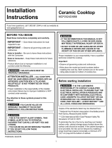
Thermador Glass Ceramic Cooktops
Models: CEF, CEP, CET
PAN
SIZE
ZONE
SMART™
PANEL
LOCK
POWER
1
9
8
7
6
5
4
3
2
KEEP
WARM
1
9
8
7
6
5
4
3
2
KEEP
WARM
PAN
SIZE
ZONE
SMART™
PANEL
LOCK
POWER
1
9
8
7
6
5
4
3
2
KEEP
WARM
PAN
SIZE
ZONE
SMART™
PANEL
LOCK
POWER

Installation Instructions Models: CEF304, CEF365, CET304, CET365, CEP304, CEP365, CEP456
TABLE OF CONTENTS *
*NOTE: The blocked letters, such as A, shown below, refer to illus-
trations on Pages 2 & 4. Match these to the related text pages.
Overall Dimensions A ..................................................................... 2
Power Supply B ............................................................................. 2
Cabinet Preparation and Clearances C ......................................... 2, 3
Junction Box Location D ................................................................. 2
Countertop Cutout Dimensions E .................................................... 2
Installing the Cooktop F ................................................................. 4
Secure Cooktop to Countertop G .................................................... 4
Solid Surface Countertop Installs H ................................................. 4
Installation above a Single Oven I, J, K, and L ............................... 4
Electrical Connection ...................................................................... 5
OVERALL DIMENSIONS
A
See Illustration A, Page 2. These dimensions are
overall.
POWER SUPPLY B
ELECTRICAL POWER CONNECTION FOR
COOKTOP
Power Supply is dual rated: 240 Volts or 208 Volts, 4
wire, 60 Hz, with the following circuit breaker
requirements:
Models CEF304, CET304 or CEP304 at
30 Amps; Models CEF365, CET365 or CEP365 at 40
Amps or Model CEP456 at 50 Amps
Install a junction box (not supplied), below the counter
top within 3 feet of flexible conduit (supplied) located
at the right rear corner of the cooktop rough-in box.
IMPORTANT: Save these instructions for Local Electrical Inspector’s use.
INSTALLER: Please leave these Installation Instructions with this unit for the owner.
OWNER: Please retain these instructions for future reference.
JUNCTION BOX LOCATION
D
Plan the installation of the unit so that the location of
the junction box is within 3 feet of the right rear of the
cooktop bottom. It must be accessible from the
front of the cabinet. (An exception to this location
would be for a cooktop installation over a single electric
oven In that situation, refer to Pages 4 and 5 and
Figures I, J, K and L.
PAGE 1
READ AND SAVE THESE INSTRUCTIONS

Installation Instructions
Models: CEF304, CEF365, CET304, CET365, CEP304, CEP365, CEP456
PAGE 2
AB
C
D
%
)ODW$UHD
)ODW$UHD
)ODW$UHD
&
0LQXPXP
6HWEDFN'LVWDQFH
IURPIURQWHGJHRIFRXQWHU
WRSWRIURQWHGJHRIFXWRXW
)ODW$UHD
Models CEF304, CET304, CEP304: Width 31"
Models CEF365, CET365, CEP365: Width 37"
Models CEP456: Width 46"
All Models: Depth 21-5/8"
Height above countertop: 1/4"
Models CEF304, CET304, CEP304: 30 Amp circuit
breaker
Models CEF365, CET365, CEP365: 40 Amp circuit
breaker
Models CEP456: 50 Amp circuit breaker
CEF, CET and CEP
Models: 240 Volt, 4 Wire, 60 Hz
208 Volt, 4 Wire, 60 Hz
Minimum Cabinet Clearances
Junction Box Location
Overall Dimensions Power Supply
Cabinet
Bottom
(unprotected)
Building
Back
Wall
Building
Side Wall
Cooking
Surface
30" Min.
(762mm)
Conduit
(Approx. 3 Ft)
12" Approximate
J Box
*(For solid surface countertop installations, use maximum cutout dimensions and consult solid surface manufacturer for specific directions.)
E
CEF304,CEP304, B 19 7/8 / (505) 20 / (508)
CET304 C 28 3/4 / (731) 20 7/8 (530)
CEF365,CEP365, B 19 7/8 / (505) 20/ (508)
CET365 C 34 3/4 / (883) 35 / (891)
CEP465 B 19 7/8 / (505) 20 / (508)
C 43 3/4 / (1111) 43 7/8/ (1114)
COUNTER CUTOUT DIMENSIONS
Minimum in./(mm)
Maximum* in./(mm)
MODEL NOs.
DIM

Installation Instructions Models: CEF304, CEF365, CET304, CET365, CEP304, CEP365, CEP456
PAGE 3
CABINET PREPARATION AND
CLEARANCES
COUNTERTOP CUTOUT
DIMENSIONS
The cutout dimensions depend upon whether the
installation is for replacement, new construction, or
installation in a solid surface countertop material, such
as Surell™, Corian
®
etc. These materials require larger
cutouts, use of heat reflective tape and rounded
corners. Drawings G and H provide some guidelines
only (see Page 4). Always consult the countertop
manufacturer for specific Installation Instructions.
INSTALLING THE COOKTOP
WARNING:
DISCONNECT POWER BEFORE INSTALLING.
BEFORE TURNING POWER “ON”, BE SURE THAT
ALL CONTROLS ARE IN “OFF” POSITION
SECURE COOKTOP TO
COUNTERTOP
The cooktop should be secured to the countertop using
the hold-down brackets provided. Prior to inserting
cooktop into cutout, turn cooktop upside down and
attach brackets to the burner box using the washers
and screws.
Place cooktop into cutout. Insert clamping screw into
the bracket and secure cooktop to countertop.
Use a wood block to protect fragile countertop
materials.
C
E
G
To eliminate the risk of burns or fire by reaching over
heated surface units, cabinet storage space located
above the surface units should be avoided. If cabinet
storage is to be provided, the risk can be reduced by
installing a range hood that projects horizontally a
minimum of 5 in. (127 mm) beyond the bottom of the
cabinets. See C, Page 2.
This unit is designed for installation in the counter top
with zero clearance to adjacent walls and projecting
surfaces constructed of combustible materials. A 30-
inch minimum clearance is required between the top
of the cooktop and the bottom of an unprotected
cabinet. A 24 inch minimum distance is necessary
when the bottom of the wood or metal cabinet is
protected by not less than 1/4 inch of a flame retardant
material covered with not less than No. 28 MSG sheet
steel, 0.015 inch (0.4 mm) thick stainless steel, 0.024
inch (0.6 mm) aluminum, or 0.020 inch (0.5 mm) thick
copper. Flame retardant materials bear the mark:
UNDERWRITERS LABORATORIES INC.
CLASSIFIED
MINERAL AND FIBER BOARDS
SURFACE BURNING CHARACTERISTICS
Followed by the flame spread and smoke ratings., these
designations are shown as “FHC (Flame Spread)/
(Smoke Developed)”. Materials with “O” flame spread
ratings are flame retardant. Local codes may allow other
flame spread ratings.
The minimum horizontal clearance from the sides and
back edge of the cooktop to the adjacent vertical
combustible walls is 0 Inches.
F

Installation Instructions
Models: CEF304, CEF365, CET304, CET365, CEP304, CEP365, CEP456
PAGE 4
F
G
H
I
J
K
L
&
&
&
&
&
Hold Down Brackets
Foam Tape Sealant
Solid Surface Countertop Installation
Optional Cooktop Installation Over Single 30" Electric Oven
Mark Center Lines of Cooktop Cutout
Mark Center Lines of S301, C301 or
SC301 Oven and Cooktop Cutout
Locations of Oven Junction Box and
Vent Hole
Vertical Opening of Oven Cutout
Swivel Conduit
Connector
Foam Tape
Sealant
Wood Block
Burner Box
Bracket
Adjusting
Screw
Shows location of
aluminum
reflective tape
Tape top and vertical
sides of cutout
4" Nominal
Toe Space
Cooktop
Conduit
3-5/8" Min.
27-3/8"
3/4"
4" Nominal
Toe Space
2 x 4 Supports
Exposed edge must
be a finish-cut
7" Dia. Hole for 4" Dia. Vent Pipe
(Duct for external vent oven only)
Oven frame
3/8" overlap
No frame
overlap
bottom
J Box for
oven
conduit
J Box for
cooktop
conduit
Oven frame
5/8" Overlap
Typ.

Installation Instructions Models: CEF304, CEF365, CET304, CET365, CEP304, CEP365, CEP456
PAGE 5
SOLID SURFACE COUNTERTOPS H
Always consult the countertop manufacturer for
specific instructions.
Countertops made from natural (i.e. granite and
marble) or SOLID SURFACE MATERIALS, such as
Surell™ and Corian
®
, require special cutout preparation
and installation procedures. Follow the guidelines in
preparing the cutout dimensions. Refer to Pages 2 and
3.
Install the cooktop as follows:
1. Round the cutout corners according to instructions
from the countertop manufacturer.
2. Apply heat reflective tape (such as Scotch
Aluminum Foil Tape #425 or #427) around the
cutout so that it folds over the top and side
surfaces. Be sure the tape extends beyond the
outermost flange of the cooktop. All corners should
also be covered with tape.
3. Attach brackets to the burner box using washers
and screws provided. Use a wooden block
underneath the countertop before tightening the
bracket screws.
4. Center cooktop in the cutout to insure adequate
clearance between the burner box and countertop
edge. (A light pencil mark along the center of front
edge and side edge of cooktop and counter will
aid positioning of the cooktop in the center.)
5. Trim excess aluminum tape along the frame edges.
BE CAREFUL not to scratch the countertop.
Installation above an oven, S301, SC301,
C301, CM 301 (Optional) I
, J
, K
, and L
.
The cooktop can be installed over a single Thermador
®
electric oven. The cooktop should be located on the
same center line as the under-the-counter single oven.
If a single oven is installed under the cooktop, see
Figure K for the location of the junction boxes.
NOTE: Thermador single oven Models S301, SC301,
C301 and CM 301 installed under-the-counter with a
Thermador
®
electric cooktop over it is a UL approved
installation.
ELECTRICAL CONNECTION
1. Attach flexible conduit to the junction box.
2. Connect the cooktop lead wires to the junction
box supply wires in proper phase:
For CEF, CET AND CEP models, connect black
(L1) to black, red (L
2) to red, green wire to
ground, white neutral to white.
NOTE: If the cooktop is installed and connected as
specified above, it will be completely grounded in
compliance with the National Electrical Code.
3. Remove everything from the cooktop surface and
apply Cooktop Cleaning Creme (packaged with
cooktop), as directed in Care & Use Manual, Page
14.
4. Turn on power supply.
5. Test operation.
CAUTION:
Your cooktop surface needs to be cleaned daily. Refer
to the Care and Use section before using it for the first
time.

Installation Instructions
Models: CEF304, CEF365, CET304, CET365, CEP304, CEP365, CEP456
BEFORE CALLING FOR SERVICE
If the elements do not heat or if the indicator “on” light does not glow, check the power source to see
if a fuse has blown or if the circuit breaker has tripped.
Refer to the Cooktop Warranty on Page 17 of the Care and Use Manual.
PRODUCT DATA PLATE
The data plate shows the model and serial number of your cooktop. It is located in the center front
area of the rough-in box, underneath the cooktop and printed on the back cover.
Keep your invoice or escrow papers for warranty validation, if service is needed.
PAGE 6

ANTES DE SOLICITAR SERVICIO
Cuando no se calientan los elementos o cuando no se ilumina la luz indicadora de "encendido", revise
la fuente de alimentación eléctrica para ver si se quemó un fusible o si se desconectó el interruptor
principal.
Consulte la Garantía de la Estufa en la página 17 del Manual de Uso y Cuidado
PLACA CON INFORMACIÓN DEL PRODUCTO
La placa con información muestra el modelo y el número de serie de su estufa. Se encuentra en el
área central delantera de la caja empotrada, abajo de la estufa y está impresa en la contraportada.
Guarde su factura o papeles para la validación de la garantía, cuando se requiere servicio.
PÁGINA 6
5551 McFadden Avenue, Huntington Beach, CA 92649 • 800/735-4328
9000064002 (No ECO) • 10012 Rev A • 01/05 © 2005 BSH Home Appliances Corp. • Litho in U.S.A.
Specifications are for planning purposes only. Refer to installation instructions and consult your countertop supplier prior to making counter
opening. Consult with a heating and ventilating engineer for your specific ventilation requirements. For the most detailed information, refer
to installation instructions accompanying product or write Thermador indicating the model number.
We reserve the right to change specifications or design without notice. Some models are certified for use in Canada. Thermador is not
responsible for products which are transported from the United States for use in Canada. Check with your local Canadian distributor or
dealer. Thermador, 5551 McFadden Avenue, Huntington Beach, CA 92649.
For the most up to date critical installation dimensions by fax, use your fax handset and call 702/833-3600. Use code #8030.
/