Page is loading ...

5
English
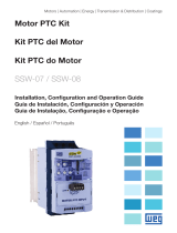
Figure 1 -Identificationofslotsoftheoptionalmodules
-slot1:white
-slot2:yellow
-slot3:green
Installation, Configuration and Operation Guide
Temperature Transducers Module IOE
l. SAFETY INFORMATION
Allsafetyproceduresdescribedinthemanualmustbefollowed.
ll. GENERAL INFORMATION
Thisuserguideprovidesinformationforinstallation,configurationandoperation
oftheoptionalmodulesIOE-01,IOE-02andIOE-03.
ThesemodulesareusedtoconnecttemperaturesensorsofthetypePTC(IOE-01),
PTC100(IOE-02)andKTY84(IOE-03).
NOTE!
TheIOE-0xaccessoriescanbeusedonlywithCFW-11invertersthathave
softwareversionV2.00orhigher.
lll. PACKAGE CONTENTS
-Accessorymoduleinanti-staticpackaging.
-Installation,configurationandoperationguide.
-Fixingscrew.
1. MODULE INSTALLATION
TheoptionalboardmodulesareinstalleddirectlyintoslotsontheCFW-11control
module.

6
English
TocorrectlyinstallmodulesIOE-01,IOE-02andIOE-03,followthestepsbelow:
Step 1: Whilethedrive is powered off, remove the front cover of the CFW-11
(figure2);
Step 2:Carefullyconnectthemoduleintoslot1(figure3(a));
Step 3: Placeandfastenthefixingscrewofthemodule(figure3(b));
Step 4: ConnectthecablesofthesensorsintheXC12(IOE-01),XC13(IOE-02)
andXC14(IOE-03).
Figure 2 -Removalofthefrontcover
Figure 3 - Installationoftheoptionalmoduleintoslot
b
c
a
a
b

7
English
2. TECNICAL SPECIFICATIONS
2.1 Connection and Indications
XC12 Function Specications
1 FC1 CurrentsourceforSensor1 2mA±7%
2 SEN1 Sensor1input 0to10Vdc;Rin=442kΩ
3 GND* 0Vreferenceforthesensorsinput Isolatedfromthegroundoftheinverter
4 FC2 CurrentsourceforSensor2 2mA±7%
5 SEN2 Sensor2input 0to10Vdc;Rin=442kΩ
6 GND* 0Vreferenceforthesensorsinput Isolatedfromthegroundoftheinverter
7 FC3 CurrentsourceforSensor3 2mA±7%
8 SEN3 Sensor3input 0to10Vdc;Rin=442kΩ
9 GND* 0Vreferenceforthesensorsinput Isolatedfromthegroundoftheinverter
10 FC4 CurrentsourceforSensor4 2mA±7%
11 SEN4 Sensor4input 0to10Vdc;Rin=442kΩ
12 GND* 0Vreferenceforthesensorsinput Isolatedfromthegroundoftheinverter
13 FC5 CurrentsourceforSensor5 2mA±7%
14 SEN5 Sensor5input 0to10Vdc;Rin=442kΩ
15
GND* 0Vreferenceforthesensors Isolatedfromthegroundoftheinverter
16
17
18
PTC-1
PTC-3
PTC-2
PTC-4
PTC-5
Figure 4 - ConnectorXC12–IOE-01
Type PTC Simple and Triple
Alarm/Faultindicationvalue
(1)
PTCsimple:1300Ω±10%
PTCtriple:4000Ω±10%
ResetValue
PTCsimple:550Ω±10%
PTCtriple:1650Ω±10%
Note:
(1) Programmabletoalarmorfault.RefertotheCFW-11ProgrammingManualforfurtherdetails.
Table 1 - PTCinput’selectricalspecifications

8
English
XC13 Function Specications
1 FC1 CurrentsourceforSensor1 2mA±0.5%
2 SEN1 Sensor1input 0to0.41Vdc;Rin=1MΩ
3 GND* 0Vreferenceforthesensorsinput Isolatedfromthegroundoftheinverter
4 FC2 CurrentsourceforSensor2 2mA±0.5%
5 SEN2 Sensor2input 0to0.41Vdc;Rin=1MΩ
6 GND* 0Vreferenceforthesensorsinput Isolatedfromthegroundoftheinverter
7 FC3 CurrentsourceforSensor3 2mA±0.5%
8 SEN3 Sensor3input 0to0.41Vdc;Rin=1MΩ
9 GND* 0Vreferenceforthesensorsinput Isolatedfromthegroundoftheinverter
10 FC4 CurrentsourceforSensor4 2mA±0.5%
11 SEN4 Sensor4input 0to0.41Vdc;Rin=1MΩ
12 GND* 0Vreferenceforthesensorsinput Isolatedfromthegroundoftheinverter
13 FC5 CurrentsourceforSensor5 2mA±0.5%
14 SEN5 Sensor5input 0to0.41Vdc;Rin=442kΩ
15
GND* 0Vreferenceforthesensors Isolatedfromthegroundoftheinverter
16
17
18
PT100-1
PT100-3
PT100-2
PT100-4
PT100-5
Figure 5 - ConnectorXC13–IOE-02
ATTENTION!
Ifsensor1isnotusedconnectawirebetweenterminalsXC13:1and
2.Proceedinthesamewayforsensor2interconnectingXC13:4and
5, for the sensor 3 interconnecting XC13: 7 and 8, for the sensor 4
interconnectingXC13:10and11andforthesensor5interconnecting
XC13:13and14.
Temperature
Indications
(1)
Range -20to+200°C
Resolution 1°C
Accuracy ±5°C
FaultLevels
(1)
Adjustablebyparameters
AlarmLevels
(1)
10°Cbelowthefaultlevels
Standard EN60751
Note:
(1) SeethenumbersoftheparametersandfurtherdetailsintheCFW-11ProgrammingManual.
Table 2 - PT100inputselectricalspecifications

9
English
XC14 Function Specications
1 FC1 CurrentsourceforSensor1 1.03mA±2%
2 SEN1 Sensor1input 0to1.77Vdc;Rin=1MΩ
3 GND* 0Vreferenceforthesensorsinput Isolatedfromtheinverter’sground
4 FC2 CurrentsourceforSensor2 1.03mA±2%
5 SEN2 Sensor2input 0to1.77Vdc;Rin=1MΩ
6 GND* 0Vreferenceforthesensorsinput Isolatedfromtheinverter’sground
7 FC3 CurrentsourceforSensor3 1.03mA±2%
8 SEN3 Sensor3input 0to1.77Vdc;Rin=1MΩ
9 GND* 0Vreferenceforthesensorsinput Isolatedfromtheinverter’sground
10 FC4 CurrentsourceforSensor4 1.03mA±2%
11 SEN4 Sensor4input 0to1.77Vdc;Rin=1MΩ
12 GND* 0Vreferenceforthesensorsinput Isolatedfromtheinverter’sground
13 FC5 CurrentsourceforSensor5 1.03mA±2%
14 SEN5 Sensor5input 0to1.77Vdc;Rin=1MΩ
15
GND* 0Vreferenceforthesensors Isolatedfromtheinverter’sground
16
17
18
KTY84-1
KTY84-2
KTY84-3
KTY84-4
KTY84-5
Figure 6 - ConnectorXC14–IOE-03
ATTENTION!
Ifsensor1isnotusedconnectawirebetweenterminalsXC14:1and
2.Proceedinthesamewayforsensor2interconnectingXC14:4and
5, for the sensor 3 interconnecting XC14: 7 and 8, for the sensor 4
interconnectingXC14:10and11andforthesensor5interconnecting
XC14:13and14.
Temperature
Indications
(1)
Range -20to+200°C
Resolution 1°C
Accuracy ±10°C
FaultLevels
(1)
Adjustablebyparameters
AlarmLevels
(1)
10°Cbelowthefaultlevels
Note:
(1) Seethenumbersoftheparameters,faultnumbers,alarmsandfurtherdetailsintheCFW-11
ProgrammingManual.
Table 3 - KTY84inputselectricalspecifications

10
English
2.2 Cable Recommendations to Connect the Sensors
Useshieldedcableswithwiregaugebetween0.14mm
2
(26AWG)and1.5mm
2
(15AWG).Connecttheshieldinthecontrolgroundplate.RefertotheCFW-11
User’sGuideforfurtherdetails.
2.3 Insulation
Thecircuitconnectedinthesensorshavestronginsulationfromtheotherscircuits
inthecontrolboard.Butit’srecommendedthatallthesensorsbealwaysisolated
fromthelivepartsofthemotor.
3. FIRST TIME START-UP
Step 1: Afterinstallthemoduleandconnectedyourcables,energizetheinverter;
Step 2: Checkifthemodulewascorrectlyidentifiedbythecontrol:25xx(IOE-01),
23xx(IOE-02)or27xx(IOE-03);
Step 3: Setuptheparametersrelatedwiththeusedmoduleaccordingwiththe
applicationneeds.RefertotheCFW-11ProgrammingManualforfurther
details.

WEG Equipamentos Elétricos S.A.
Jaraguá do Sul - SC - Brazil
Phone 55 (47) 3276-4000 - Fax 55 (47) 3276-4020
São Paulo - SP - Brazil
Phone 55 (11) 5053-2300 - Fax 55 (11) 5052-4212
automacao@weg.net
www.weg.net
Document: 10000545263 / 01
/