NetSafety UVS Flame Detector-ATEX Owner's manual
- Type
- Owner's manual
NetSafety UVS Flame Detector-ATEX
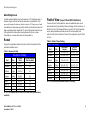
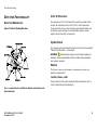
The NetSafety UVS Flame Detector-ATEX is a smart, stand-alone fire detector designed to respond to UV radiation emitted by a wide range of fires, including hydrocarbon, hydrogen, and metal-based fires. It is ideal for various applications, including:
- Automotive manufacturing and paint spray booths
- Aircraft hangars
- Offshore platforms, refineries, pipelines, and production ships
- Printing industry facilities
- Oil, gas, and petrochemical refineries/production/storage/offloading/shipping
- Warehouses (flammable liquids/toxic gases) and tank farms
- Power generation pumps, generators, and unmanned stations
NetSafety UVS Flame Detector-ATEX
The NetSafety UVS Flame Detector-ATEX is a smart, stand-alone fire detector designed to respond to UV radiation emitted by a wide range of fires, including hydrocarbon, hydrogen, and metal-based fires. It is ideal for various applications, including:
- Automotive manufacturing and paint spray booths
- Aircraft hangars
- Offshore platforms, refineries, pipelines, and production ships
- Printing industry facilities
- Oil, gas, and petrochemical refineries/production/storage/offloading/shipping
- Warehouses (flammable liquids/toxic gases) and tank farms
- Power generation pumps, generators, and unmanned stations


-
 1
1
-
 2
2
-
 3
3
-
 4
4
-
 5
5
-
 6
6
-
 7
7
-
 8
8
-
 9
9
-
 10
10
-
 11
11
-
 12
12
-
 13
13
-
 14
14
-
 15
15
-
 16
16
-
 17
17
-
 18
18
-
 19
19
-
 20
20
-
 21
21
-
 22
22
-
 23
23
-
 24
24
-
 25
25
-
 26
26
-
 27
27


NetSafety UVS Flame Detector-ATEX Owner's manual
- Type
- Owner's manual
NetSafety UVS Flame Detector-ATEX
The NetSafety UVS Flame Detector-ATEX is a smart, stand-alone fire detector designed to respond to UV radiation emitted by a wide range of fires, including hydrocarbon, hydrogen, and metal-based fires. It is ideal for various applications, including:
- Automotive manufacturing and paint spray booths
- Aircraft hangars
- Offshore platforms, refineries, pipelines, and production ships
- Printing industry facilities
- Oil, gas, and petrochemical refineries/production/storage/offloading/shipping
- Warehouses (flammable liquids/toxic gases) and tank farms
- Power generation pumps, generators, and unmanned stations
Ask a question and I''ll find the answer in the document
Finding information in a document is now easier with AI
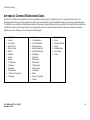
Related papers
-
NetSafety UVS-H2 Flame Detector Owner's manual
-
NetSafety UVS-A or AR Flame Detector Owner's manual
-
NetSafety TL-UV/IR Test Lamp Kit Owner's manual
-
-
-
-
-
-
-
Other documents
-
Comelit 30009009 User manual
-
 Kromschroder UVS 5, UVS 10 Datasheet
-
Shure MVi User guide
-
DeLOCK 46124 Datasheet
-
-
SMC SMC 3200/3300 UV/IR Wet Bench Flame Detector Owner's manual
-
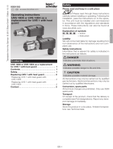 Kromschroder UVS 10 Operating instructions
-
 Kromschroder UVS 6, 8 Operating instructions
-
Sierra Monitor Corporation 3100-06 User manual
-
EDWARDS 5000 User manual


