
1
S6161-LR-FSE-010
0910-LP-527-3200
OPERATION AND SERVICE MANUAL
FOR
SHIPBOARD ELECTRIC DROP-IN GRIDDLE
MODEL NUMBERS:
136TDI-VG, 148TDI-VG, 172TDI-VG,
LANG MANUFACTURING
DIVISION OF STAR MANUFACTURING INTERNATIONAL
10 SUNNEN DRIVE
ST. LOUIS, MO, 63143
DISTRIBUTION STATEMENT
THIS PUBLICATION IS REQUIRED FOR OFFICIAL USE OR FOR
ADMINISTRATIVE OR OPERATIONAL PURPOSES. DISTRIBUTION IS LIMITED
TO U.S. GOVERNMENT AGENCIES ONLY. OTHER REQUESTS FOR THIS
DOCUMENT MUST BE REFERRED TO COMMANDER, NAVAL SEA SYSTEMS
COMMAND, SEA 09, WASHINGTON, DC 20362
SUPERCEDURE NOTICE
CANCELS AND SUPERCEDES S6161-LR-FSE-010
DATED MARCH 2002
AND ALL CHANGES THERETO
Star Manufacturing International 10 Sunnen Drive, St. Louis, MO 63143
Part No. 2M-W357 Phone: 314-781-2777, Fax: 314-781-2714
Rev. - www.Star-mfg.com
April, 24, 2007

2
MANUAL SUPPLEMENT FOR MARINE EQUIPMENT
THIS EQUIPMENT IS APPROVED FOR INSTALLATION ONLY ON
VESSELS GREATER THAN 65 FEET IN LENGTH IN
ACCORDANCE WITH USCG REGULATIONS IN TITLE 46 CFR 110-
113.
ANY WIRING USED IN THE INSTALLATION OF THIS APPLIANCE
MUST BE STRANDED COPPER.

3
0910-LP-572-3200
APRIL 2007
IDENTIFYING TECHNICAL PUBLICATION SHEET
1. IDENTIFICATION DATA:
2. PURPOSE: THIS TECHNICAL PUBLICATION IS ISSUED FOR THE PURPOSE
OF IDENTIFYING AN AUTHORIZED TECHNICAL MANUAL FOR NAVY USE
AND FOR PROVIDING SUPPLEMENTAL TECHNICAL INFORMATION.
A. MANUFACTURER: STAR MFG. INTERNATIONAL.
B. CONTRACT NUMBER: _________________________________________
C. EQUIPMENT: GRIDDLE, SELF HEATING, ELECTRIC
D. REQUISITION NUMBER: NOT REFERENCED
E. NATIONAL STOCK NUMBER (NSN): ____________________________
F. TITLE: MAINTENANCE MANUAL FOR GRIDDLE, SELF HEATING,
ELECTRIC
G. DATE OF PUBLICATION: APRIL 2007
H. PREPARING ACTIVITY: DEFENSE GENERAL SUPPLY CENTER
I. APPLICABLE TMCR NUMBER: 860172
J. EXTENT OF PROPOSED SUPPLEMENTAL DATA (10% MAXIMUM): 1%
K. LIST OF TECHNICAL MANUAL FOR THIS EQUIPMENT PROCURED
UNDER ANOTHER CONTACT:
3. ADDITIONAL COPIES: ADDITIONAL COPIES ARE AVAILABLE FROM:
NAVAL PUBLICATION AND FORMS CENTER
5801 TABOR AVENUE
PHILADELPHIA, PA 19120-5099
4. COVER: THE TECHNICAL MANUAL OUTSIDE COVER SHALL CONTAIN
THE FOLLOWING STATEMENTS:
PUBLISHED BY DIRECTION OF COMMANDER, NAVAL SEA SYSTEMS
COMMAND

4
S6161-LR-FSE-010
0910-LP-527-3200
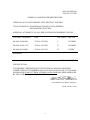
APPROVAL AND PROCUREMENT RECORD
APPROVAL DATA FOR: GRIDDLE, SELF-HEATING, ELECTRIC
TITLE OF MANUAL: MAINTENANCE MANUAL FOR: GRIDDLE,
SELF-HEATING, ELECTRIC
APPROVAL AUTHORITY: NAVAL SHIP SYSTEMS ENGINEERING STATION
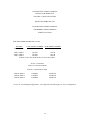
CONTRACT NUMBER NSN # OF UNITS APL/CID
DLA441-92-M-2844 7310-01-359-2844 6 LG72MDI
DLA441-92-M-Y175 7310-01-359-2845 13 LG36MDI
DLA400-86-D-0090 7310-01-104-1214 14 LG48M
REMARKS:
DATE: MARCH 2002
CERTIFICATION:
IT IS HEREBY CERTIFIED THAT THE TECHNICAL MANUAL PROVIDED
UNDER CONTRACT NUMBER DLA441-92-M-2844, DLA441-92-M-Y175, DLA400-
86-D-0090 FOR LANG LG72MDI, LG36MDI, AND LG48M HAS BEEN APPROVED
BY THE APPROVAL DATA SHOWN ABOVE:
______________________________
DIRECTOR, GOV’T CONTRACTS
LANG MANUFACTURING COMPANY
FSCM / CAGE #: 34931

5
CHANGE RECORD
Change no. Date Title and/or Brief Description
Signature of
Validating Officer

6
TABLE OF CONTENTS
CHAPTER PAGE
1. TABLE OF CONTENTS ............................................................................... 6
2. LIST OF ILLUSTRATIONS.......................................................................... 7
3. READ FIRST ................................................................................................. 8
4. SPECIFICATIONS ........................................................................................ 11
5. EQUIPMENT DESCRIPTION ...................................................................... 14
6. INSTALLATION ........................................................................................... 16
7. OPERATION.................................................................................................. 18
8. MAINTENANCE & TROUBLESHOOTING PROCEDURES .................... 19
9. PARTS LIST .................................................................................................. 24
10. WIRING DIAGRAMS ................................................................................... 26
11. WARRANTY ................................................................................................. 28

7
LIST OF ILLUSTRATIONS
FIGURE # TITLE OF ILLUSTRATION PAGE #
1 Specification Sheets 11 to 20
2 MDI-36 Cut Out 21
3 MDI-48 Cut Out 22
4 MDI-72 Cut Out 23
5 Leg Pad Layout 27
6 Sensor Location (Calibration) 31
7 Wiring Diagram 208/240V 34
8 Wiring Diagram 480V 35

8
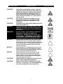
IMPORTANT READ FIRST IMPORTANT
CAUTION: THE GRIDDLE IS EXTREMELY HEAVY. FOR SAFE
HANDLING, INSTALLER SHOULD OBTAIN HELP AS
NEEDED, OR EMPLOY APPROPRIATE MATERIALS
HANDLING EQUIPMENT (SUCH AS A FORKLIFT,
DOLLY, OR PALLET JACK) TO REMOVE THE UNIT
FROM THE SKID AND MOVE IT TO THE PLACE OF
INSTALLATION.
CAUTION: ANY STAND, COUNTER OR OTHER DEVICE ON
WHICH GRIDDLE WILL BE LOCATED MUST BE
DESIGNED TO SUPPORT THE WEIGHT OF THE
GRIDDLE(S).
CAUTION: SHIPPING STRAPS ARE UNDER TENSION AND CAN
SNAP BACK WHEN CUT.
DANGER: THIS APPLIANCE MUST BE GROUNDED AT THE
TERMINAL PROVIDED. FAILURE TO GROUND THE
APPLIANCE COULD RESULT IN ELECTROCUTION
AND DEATH.
WARNING: INSTALLATION OF THE UNIT MUST BE DONE BY
PERSONNEL QUALIFIED TO WORK WITH
ELECTRICITY. IMPROPER INSTALLATION CAN
CAUSE INJURY TO PERSONNEL AND/OR DAMAGE
TO EQUIPMENT. UNIT MUST BE INSTALLED IN
ACCORDANCE WITH ALL APPLICABLE CODES.
NOTICE: The data plate is located next to the grease drawer,
behind access panel. The griddle voltage, wattage,
serial number, wire size, and clearance specifications
are on the data plate. This information should be
carefully read and understood before proceeding
with the installation.
NOTICE: The installation of any components such as a vent
hood, grease extractors, fire extinguisher systems,
must conform to their applicable National, State and
locally recognized installation standards.
NOTICE: During the first few hours of operation you may
notice a small amount of smoke coming off the
griddle surface, and a faint odor from the smoke.
This is normal for a new griddle and will disappear
after the first few hours of use.
CAUTION: ALWAYS KEEP THE AREA NEAR THE APPLIANCE
FREE FROM COMBUSTIBLE MATERIALS.
CAUTION: KEEP FLOOR IN FRONT OF EQUIPMENT CLEAN
AND DRY. IF SPILLS OCCUR, CLEAN IMMEDIATELY,
TO AVOID THE DANGER OF SLIPS OR FALLS.

9
IMPORTANT READ FIRST IMPORTANT
WARNING: KEEP WATER AND SOLUTIONS OUT OF CONTROLS.
NEVER SPRAY OR HOSE CONTROL CONSOLE,
ELECTRICAL CONNECTIONS, ETC.
CAUTION: MOST CLEANERS ARE HARMFUL TO THE SKIN, EYES,
MUCOUS MEMBRANES AND CLOTHING.
PRECAUTIONS SHOULD BE TAKEN TO WEAR RUBBER
GLOVES, GOGGLES OR FACE SHIELD AND
PROTECTIVE CLOTHING. CAREFULLY READ THE
WARNING AND FOLLOW THE DIRECTIONS ON THE
LABEL OF THE CLEANER TO BE USED.
NOTICE: Service on this, or any other, LANG appliance must be
performed by qualified personnel only. Consult your
LANG authorized service agent directory or call the
factory at 1-800-438-5264 or WWW.STAR-MFG.COM
For the service agent nearest you.
WARNING: BOTH HIGH AND LOW VOLTAGES ARE PRESENT
INSIDE THIS APPLIANCE WHEN THE UNIT IS
PLUGGED/WIRED INTO A LIVE RECEPTACLE. BEFORE
REPLACING ANY PARTS, DISCONNECT THE UNIT
FROM THE ELECTRIC POWER SUPPLY.
CAUTION: USE OF ANY REPLACEMENT PARTS OTHER THAN
THOSE SUPPLIED BY LANG OR THEIR AUTHORIZED
DISTRIBUTORS CAN CAUSE BODILY INJURY TO THE
OPERATOR AND DAMAGE TO THE EQUIPMENT AND
WILL VOID ALL WARRANTIES.

10
LANG MANUFACTURING COMPANY
MANUAL FOR MODEL ECO
ELECTRIC CONVECTION OVENS
ISSUE DATE FEBRUARY 1999
LANG MANUFACTURING COMPANY
6500 MERRILL CREEK PARKWAY
EVERETT, WA 98203
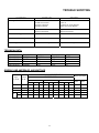
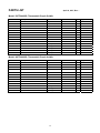
ELECTRIC GRIDDLES PER: MIL-G-2338L
MIL SPEC
LANG MODEL NUMBER STAR MODEL NUMBER
TYPE I, SIZE 2* LG-36M 136T-M
TYPE I, SIZE 3* LG-72M 172T-M
TYPE I, SIZE 5* LG-24M 124T-M
TYPE I, SIZE 6* LG-48M 148T-M
TYPE II- Use the same model number as above Then add for:
STYLE 1- with Stand
STYLE 2- with Castered Stand
STYLE 3- with Bolt Down Stand
TYPE III, SIZE 2* LGMDI36 136TDI-VG
TYPE III, SIZE 3* LGMDI72 172TDI-VG
TYPE III, SIZE 6* LGMDI48 148TDI-VG
* N.S.A. for “Naval Shipboard Application”. All components will fit through a 26” X 66” watertight door.

7
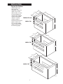
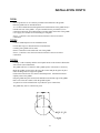
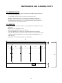
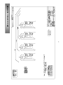
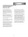
INSTALLATION
Prepare the Cabinet
Cabinet base must
have cross air
ventilation. It does not
matter if it is on the
ends or sides. If vents
are not installed, the
controls may overheat
rendering the griddle
useless. For best
results, provide a
knockout for the control
panel a minimum of
4½”- from the griddle
support surface as on
the following pages.
36.750”
30.60”
30.00”
26.750”
31.750”
36.00”
48.750”
37.10”
34.00”
26.750”
32.00”
36.00”
60.750”
38.00”
26.750”
6.5”
7.0”
32.00”
36.00”
4.5”
6.0”
6.5”
7.0”
4.5”
6.0”
6.5”
7.0”
4.5”
6.0”
136SDI / TDI
148SDI / TDI
160SDI / TDI
Cabinet Cut-out
IL1571a

24
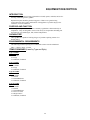
EQUIPMENT DESCRIPTION
INTRODUCTION
This manual contains the necessary information to install, operate, maintain, and service
the Lang self-heating electric griddles.
Replacement parts should be genuine Lang parts. Failure to use genuine Lang
replacement parts may result in malfunction of the appliance or possible injury to the
contractor or service technician.
PURPOSE AND FUNCTION
Electric griddles provide heated surface constantly regulated at a thermostatically set
temperature. They are designed to cook a wide variety of food products including, but
not limited to, eggs, hamburgers, fish, chicken and pancakes.
CAPABILITIES
These griddles are capable of cooking all types of products requiring contact wit a
heated surface.
ENVIRONMENTAL REQUIREMENTS
The following minimum spacing from combustible surfaces must be maintained:
Sides – 2 inches, Back – 2 inches
ITEMS FURNISHED (Listed by Type and Style)
Type I Griddle
Size 2, 5, 6
1 ea. Griddle
4 ea. Legs
2 ea. Manuals, Technical
Type I Griddle
Size 3
1 ea. Griddle
8 ea. Legs
2 ea. Manuals, Technical
Type II Griddle
Style 1
1 ea. Griddle
1 ea. Stand
1 ea. Stand Hardware
2 ea. Manuals, Technical
Type II Griddle
Style 2
1 ea. Griddle
1 ea. Stand
1 ea. Stand Hardware
2 ea. Swivel Casters
2 ea. Rigid Casters
2 ea. Manuals, Technical

25
EQUIPMENT DESCRIPTION CONT’D
Type II Griddle
Style 3
1 ea. Griddle
1 ea. Bolt Down Stand
1 ea. Stand Hardware
2 ea. Manuals, Technical
Type III Griddle
Size 1 & 6
1 ea. Griddle
1 ea. Griddle Control Panel
2 ea. Manuals, Technical
Type III Griddle
Size 3
1 ea. Griddle
2 ea. Griddle Control Panel
2 ea. Manuals, Technical
ITEMS REQUIRED
An adequate supply of wire suitable for the loads and application specified on the data
sheet must be provided. The data sheet is on Page 4 of this manual.
TOOLS AND TEST EQUIPMENT REQUIRED
For Installation:
1 set – Open End Wrenches
1 ea. – Flat Blade Screwdriver
1 ea. – Phillips Screwdriver
1 ea. – Wire Cutter/Stripper
1 ea. – AMP Probe
1 ea. – Voltmeter
For Service: All of the above plus –
1 ea. – Needle Nose Pliers
1 ea. – Crimping Pliers
1 ea. – Allen Wrench Set
1 ea. – Temperature Meter
1 ea. – Very Small Flat Blade Screwdriver
CONTROLS
A mechanical snap action thermostat (100°F-450°F) controls each 12” section of the
griddle.
A red indicator lamp indicates that the griddle is heating.

26
INSTALLATION
CAUTION: THE GRIDDLE IS EXTREMELY HEAVY. FOR SAFE
HANDLING, INSTALLER SHOULD OBTAIN HELP AS
NEEDED, OR EMPLOY APPROPRIATE MATERIALS
HANDLING EQUIPMENT (SUCH AS A FORKLIFT, DOLLY,
OR PALLET JACK) TO REMOVE THE UNIT FROM THE
SKID AND MOVE IT TO THE PLACE OF INSTALLATION.
CAUTION: ANY STAND, COUNTER OR OTHER DEVICE ON WHICH
GRIDDLE WILL BE LOCATED MUST BE DESIGNED TO
SUPPORT THE WEIGHT OF THE OVEN(S).
CAUTION: SHIPPING STRAPS ARE UNDER TENSION AND CAN
SNAP BACK WHEN CUT.
DANGER: THIS APPLIANCE MUST BE GROUNDED AT THE
TERMINAL PROVIDED. FAILURE TO GROUND THE
APPLIANCE COULD RESULT IN ELECTROCUTION AND
DEATH.
WARNING: INSTALLATION OF THE UNIT MUST BE DONE BY
PERSONNEL QUALIFIED TO WORK WITH ELECTRICITY.
IMPROPER INSTALLATION CAN CAUSE INJURY TO
PERSONNEL AND/OR DAMAGE TO EQUIPMENT. UNIT
MUST BE INSTALLED IN ACCORDANCE WITH ALL
APPLICABLE CODES.
NOTICE: The data plate is located next to the grease drawer,
behind access panel. The griddle voltage, wattage, serial
number, wire size, and clearance specifications are on the
data plate. This information should be carefully read and
understood before proceeding with the installation.
NOTICE: The installation of any components such as a vent hood,
grease extractors, fire extinguisher systems, must
conform to their applicable National, State and locally
recognized installation standards.
INSPECTION AND INSTALLATION
Upon receipt, check for freight damage, both visible and concealed. Visible damage
should be noted on the freight bill at the time of delivery and signed by the carrier's
agent. Concealed loss or damage means loss or damage which does not become
apparent until the merchandise has been unpacked. If concealed loss or damage is
discovered upon unpacking, make a written request for inspection by the carrier's agent
within 15 days of delivery. All packing material should be kept for inspection. Do not
return damaged merchandise to Lang Manufacturing Company. File your claim with
the carrier.
LOCATION
Move the crate(s) containing the oven(s) as close to the place of installation as possible
before
removing the protective crating. Uncrate the oven(s) and move them as close as
practical to the final installation site.

27
INSTALLATION CONT’D
TYPE I
Screw legs into the 3/8-16 weld nuts provided on the underside of the griddle.
Place the griddle into its intended location.
A 1 1/4-inch conduit knockout through the back and the bottom of the griddle body is
located at the rear of the griddle. A 3-pole terminal block is provided for service
connections and can be accessed through a removable panel on the back of the griddle.
Use a supply wire suitable for at least 90 degree centigrade.
Sizes 2, 5, and 6 have one electrical connection and size 3 has two electrical
connections.
TYPE II
Construct stand and place into its intended location.
For bolt down legs see illustration below for dimensions.
Carefully place griddle onto its stand.
Electric connection can be made at the rear of the griddle.
Sizes 2, 5, and 6 have one electrical connection and size 3 has two electrical
connections.
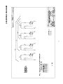
TYPE III
Carefully cut the countertop and the control panel cutouts to the clearance dimensions
shown on the cutout illustrations.
The griddle will have a control box and a griddle portion. Disconnect as necessary.
Block the griddle over the hole in the top of the counter and put the gasket in place
under the flange that will support the griddle.
Position the control boxes close to there installed position. Attach the thermostat
capillary tubes to the griddle.
Drop the griddle into place and twist the hold-downs around the edge of the griddle
that is now below the counter to lock the griddle in place.
A separate box with a terminal block is provided for power connections.
The griddle may now be connected to power

28
OPERATION
NOTICE: During the first few hours of operation you may notice a
small amount of smoke coming off the griddle surface,
and a faint odor from the smoke. This is normal for a new
griddle and will disappear after the first few hours of use.
CAUTION: ALWAYS KEEP THE AREA NEAR THE APPLIANCE FREE
FROM COMBUSTIBLE MATERIALS.
CAUTION: KEEP FLOOR IN FRONT OF EQUIPMENT CLEAN AND
DRY. IF SPILLS OCCUR, CLEAN IMMEDIATELY, TO
AVOID THE DANGER OF SLIPS OR FALLS.
OPERATING INSTRUCTIONS
An understanding of how the griddle sections are controlled will be a valuable aid in
loading your griddle.
Each 12-inch section of your griddle is independently controlled by a temperature
controller. The temperature control sensor is mounted in the center of each cooking
section under the griddle plate.
If the product is loaded directly over the temperature sensor, that section will turn on
and the burner will heat the entire cooking section. If the product is loaded to the side,
front or back of the temperature sensor, the thermostat will react to the temperature
change much slower.
During slow periods with minimal loads, do not load directly over the thermostat
sensors as this will unnecessarily turn the burners on and overheat the remainder of the
section not being utilized.
Turn the product and continue cooking until it has reached its desired degree of
doneness.
Remove the product from the griddle.
When reloading the griddle, first use the griddle surface on which a previous load was
not placed. This will help insure the proper griddle temperature.
INITIAL START-UP
Prior to putting any griddle into full time operation at normal cooking temperatures, it
must be thoroughly "seasoned" and dried out. Moisture absorption in the closed
spaces, in the insulation and even inside the heating elements can cause future trouble
if not properly treated.
Before seasoning the griddle it is first necessary to remove the shipping preservative
from the griddle surface. To do this, add a mild detergent to hot water and wash the
griddle plate. Rinse with a damp sponge and dry with a clean rag.
To "season" the griddle, set the thermostat dial to 300°. Allow unit to come up to
temperature and cycle off. Apply a thin coat of high-grade, non-salted vegetable oil to
the griddle surface. Rub the oil into the griddle surface with the flat side of a spatula
or a towel. Re-coat any dry spots that appear then wait 30 minutes and wipe off any
excess oil. Repeat these steps at 350°, 400°, and 450°.
To “dry out” the Griddle, set the thermostat to 250° and turn on the power switch.
Allow the unit to cycle at least 15 minutes at this heat level. Reset the thermostat to
350° allowing the same time. Reset the thermostat to 450° and allow the unit to
maintain the temperature for a minimum of 4 hours. More time may be required if the
unit will be operating in a moist or humid environment.
If the unit is out of use for three or more days, a one-hour preheat schedule should be
used, especially when exposed to high humidity and/or cool temperatures.

29
OPERATION CONT’D
NORMAL OPERATION
Each 12-inch section of your griddle is independently controlled by a temperature
controller. The temperature control sensor is mounted in the center of each cooking
section under the griddle plate.
Turn the griddle thermostat to the desired temperature and allow 30 minutes to preheat.
Once griddle has been preheated place product on the griddle and allow to cook.

30
MAINTENANCE AND CLEANING
WARNING: KEEP WATER AND SOLUTIONS OUT OF CONTROLS.
NEVER SPRAY OR HOSE CONTROL CONSOLE,
ELECTRICAL CONNECTIONS, ETC.
CAUTION: MOST CLEANERS ARE HARMFUL TO THE SKIN, EYES,
MUCOUS MEMBRANES AND CLOTHING. PRECAUTIONS
SHOULD BE TAKEN TO WEAR RUBBER GLOVES,
GOGGLES OR FACE SHIELD AND PROTECTIVE
CLOTHING. CAREFULLY READ THE WARNING AND
FOLLOW THE DIRECTIONS ON THE LABEL OF THE
CLEANER TO BE USED.
NOTICE: Service on this, or any other, LANG appliance must be
performed by qualified personnel only. Consult your
LANG authorized service agent directory or call the
factory at 1-800-807-9054, or WWW.STAR-MFG.COM For
the service agent nearest you.
WARNING: BOTH HIGH AND LOW VOLTAGES ARE PRESENT INSIDE
THIS APPLIANCE WHEN THE UNIT IS PLUGGED/WIRED
INTO A LIVE RECEPTACLE. BEFORE REPLACING ANY
PARTS, DISCONNECT THE UNIT FROM THE ELECTRIC
POWER SUPPLY.
CAUTION: USE OF ANY REPLACEMENT PARTS OTHER THAN
THOSE SUPPLIED BY LANG OR THEIR AUTHORIZED
DISTRIBUTORS CAN CAUSE BODILY INJURY TO THE
OPERATOR AND DAMAGE TO THE EQUIPMENT AND
WILL VOID ALL WARRANTIES.
DAILY CLEANING
Empty the grease drawer or whenever it is 3/4 full by pulling strait out toward the
front. It is easily removed for washing.
Clean the exterior of the appliance with Lang Mfg. Prima Shine (72804-41) cleaner to
maintain a gleaming appearance.
Keep the griddle surface clean. After each cooking load, scrape the griddle surface to
remove any carbonized grease
WEEKLY CLEANING
Once a week (or when necessary) the griddle surface should be cleaned and re-
seasoned. Use Lang Mfg Carbon Release (72804-32). Rub with the grain of the metal,
being careful not to scrape the splashguard.
Be sure to rinse thoroughly and re-season to prevent rusting and corrosion.

31
MAINTENANCE AND CLEANING CONT’D
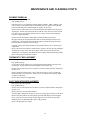
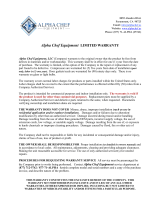
CALIBRATION CHECK
Set the griddle temperature to 350°F on all sections (it should take approximately 22
minutes to reach temperature).
Let the griddle reach 350°F and cycle off and on at least three times.
Measure 6” from the left, and 11 1/2” from the front of the plate for the first
checkpoint. This will check the center of the sensor for the first cooking section.
Each checkpoint is located every 12” to the right from the last point, and always 11
1/2” from the front. (See illustration below.)
CALIBRATION
A 1/16” flat blade screwdriver with a 2” shaft is required to make adjustments on the
thermostat.
Maintain the oven temperature at 350°.
Without turning the thermostat, remove the knob.
Locate the adjustment screw at the base of the shaft and insert the screwdriver.
Grasp the shaft and turn the screwdriver counter clockwise to increase temperature and
clockwise to decrease temperature (1/8 of a turn will move the temperature 5-7 ° in
either direction).
Reinstall the oven knob and recheck the oven temperature.
48"
12"
11
1/2"
11
1/2"
12"6" 12"
30"
5"
6"
2"

32
MAINTENANCE AND CLEANING CONT’D
ELEMENT REMOVAL
Disconnect power from griddle.
Prop griddle plate up.
Disconnect power wire attached to heating element terminals. Mark or identify each
wire to ensure correct replacement on new heating element. Inspect for frayed ends,
broken strands and grease soaked insulation. Replace as necessary.
Remove the two sheet metal screws securing the thermostat capillary tube clip to the
element pan. Pull the clip and the tube down and out of the center slot of the element
pan. Take care not to break the capillary tube, as it may be brittle from prolonged
exposure to high temperature.
Remove the nuts and washers retaining the element pan and pressure plate.
Drop the element pan straight down until studs are cleared and pull forward out of
griddle body. The elements will normally drop down with the element pan and are
now accessible for replacement as necessary.
Compare voltage and wattage marking of old element with new one to ensure proper
replacement.
Reverse the removal procedure to install the new element. Be sure the nuts holding the
element pan are snug as this will assure proper contact between the element and
griddle plate. The capillary tube bulb must also be tightly clamped against the griddle
plate to obtain proper temperature control.
THERMOSTAT REPLACEMENT
Disconnect power from griddle.
Prop griddle plate up.
Loosen the two sheet metal screws securing the thermostat capillary tube clip to the
element pan. Gently pull the thermostat capillary tube from the clip.
Remove the two sheet metal screws from the rear of the control panel box and pull off
the box cover.
Remove thermostat control knob. Loosen and remove the two screws securing the
thermostat body to the front panel. Remove wires from thermostat terminals. Mark
for proper replacement.
Reverse this procedure for replacement.
PILOT INDICATOR REPLACEMENT
Disconnect power from griddle.
Prop griddle plate up.
Remove the two sheet metal screws from the rear of the control panel box and pull off
the box cover.
Remove the wires from the pilot indicator.
The pilot light is held firmly in place by means of a spring metal speed nut on the back.
Remove the pilot indicator by removing the speed nut and pulling it out through the
front. It may be necessary to break the pilot light in two to remover he speed nut.
Install the new pilot light and hold in place with speed nut.
Reverse the procedure to reinstall.
Page is loading ...
Page is loading ...
Page is loading ...
Page is loading ...
Page is loading ...
Page is loading ...
-
 1
1
-
 2
2
-
 3
3
-
 4
4
-
 5
5
-
 6
6
-
 7
7
-
 8
8
-
 9
9
-
 10
10
-
 11
11
-
 12
12
-
 13
13
-
 14
14
-
 15
15
-
 16
16
-
 17
17
-
 18
18
-
 19
19
-
 20
20
-
 21
21
-
 22
22
-
 23
23
-
 24
24
-
 25
25
-
 26
26


Ask a question and I''ll find the answer in the document
Finding information in a document is now easier with AI
Related papers
Other documents
-
Royal Sovereign PFNC-20SE Owner's manual
-
 Lang Manufacturing LG-24 User manual
-
 ALPHA CHEF EQUIPMENT CFD-2RR--E-HC User guide
-
 AMPTO GR1E User manual
-
 Chris & Chris JET1222 Installation guide
-
Fleetwood EG618 User manual
-
Rode IXY User manual
-
Star 736TA Owner's manual
-
Badger Basket 01721 Assembly Instructions Manual
-
Hobart CG731 User manual


