
ML-95 Parts Manual
1996 Thru February 1999
American Dryer Corporation
88 Currant Road
Fall River, MA 02720-4781
Telephone: (508) 678-9000 / Fax: (508) 678-9447
E-mail: [email protected]
www.amdry.com
082997DMG/abe ADC Part No. 450155

Retain This Manual In A Safe Place For Future Reference
American Dryer Corporation products embody advanced concepts in engineering, design, and safety. If this product is
properly maintained, it will provide many years of safe, efficient, and trouble-free operation.
ONLY qualified technicians should service this equipment.
OBSERVE ALL SAFETY PRECAUTIONS displayed on the equipment or specified in the installation manual included with
the dryer.
The following “FOR YOUR SAFETY” caution must be posted near the dryer in a prominent location.
We have tried to make this manual as complete as possible and hope you will find it useful. ADC reserves the right to make
changes from time to time, without notice or obligation, in prices, specifications, colors, and material, and to change or
discontinue models.
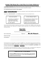
Important
For your convenience, log the following information:
DATE OF PURCHASE ____________________________ MODEL NO. __________________________________________
RESELLER’S NAME _______________________________________________________________________________________
Serial Number(s) ________________________________________________________________________________________
________________________________________________________________________________________
________________________________________________________________________________________
Replacement parts can be obtained from your reseller or the ADC factory. When ordering replacement parts from the factory,
you can FAX your order to ADC at (508) 678-9447 or telephone your order directly to the ADC Parts Department at (508)
678-9000. Please specify the dryer model number and serial number in addition to the description and part number, so that
your order is processed accurately and promptly.
The illustrations on the following pages may not depict your particular dryer exactly. The illustrations are a composite of
the various dryer models. Be sure to check the descriptions of the parts thoroughly before ordering.
“IMPORTANT NOTE TO PURCHASER”
Information must be obtained from your local gas supplier on the instructions
to be followed if the user smells gas. These instructions must be posted in a
prominent location near the dryer.
FOR YOUR SAFETY
Do not store or use gasoline or
other flammable vapors and
liquids in the vicinity of this or
any other appliance.
POUR VOTRE SÉCURITÉ
Ne pas entreposer ni utiliser d’essence
ni d’autres vapeurs ou liquides
inflammables à proximité de cet
appareil ou de tout autre appareil.
ML-95 Phase 6

Control Door Assembly .......................................................................................................................... 2
Phase 6 Microprocessor Panel Assembly for models mfd. as of February 11, 1998.................................. 3
Phase 6 Microprocessor Panel Assembly for models mfd. prior to February 11, 1998.............................. 4
Sensor Bracket Assembly ....................................................................................................................... 5
Front Panel/Main Door Assemblies for models mfd. as of October 24, 1997 ....................................... 6, 7
Front Panel/Main Door Assemblies for models mfd. prior to October 24, 1997 ................................... 8, 9
Main Door Switch for models mfd. as of October 24, 1997 .................................................................. 10
Main Door Switch for models mfd. prior to October 24, 1997 ...............................................................11
Lint Door Assembly ........................................................................................................................ 12, 13
Basket (Tumbler) Assembly .................................................................................................................. 14
Front Thruster Wheel Assembly for models mfd. between September 15, 1997 and April 6, 1998 ......... 15
Front Thruster Wheel Assembly for models mfd. prior to September 15, 1997....................................... 16
Rear Thruster Wheel Assembly for models mfd. between September 15, 1997 and April 6, 1998 .......... 17
Rear Thruster Wheel Assembly for models mfd. prior to September 15, 1997........................................ 18
Front Thruster Wheel Assembly for models mfd. as of April 6, 1998 ...................................................... 19
Rear Thruster Wheel Assembly for models mfd. as of April 6, 1998 ....................................................... 20
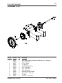
Idler Shaft Assembly for models mfd. as of December 15, 1997 ............................................................ 21
Idler Shaft Assembly for models mfd. prior to December 15, 1997 ........................................................ 22
Drive Shaft Assembly for models mfd. as of December 15, 1997 ........................................................... 23
Drive Shaft Assembly for models mfd. prior to December 15, 1997 ....................................................... 24
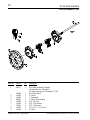
Drive Motor Assembly.......................................................................................................................... 25
Blower (Fan/Impellor) Motor Assembly ................................................................................................ 26
Sail Switch Assembly ............................................................................................................................ 27
Blower (Fan/Impellor) Wheel Assembly (with Air Jet) for models mfd. as of July 1, 1998 ................. 28, 29
Blower (Fan/Impellor) Wheel Assembly (without Air Jet) for models mfd. prior to July 1, 1998 ........ 30, 31
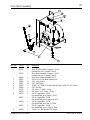
Burner Assembly ............................................................................................................................ 32, 33
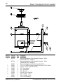
Reversing Relay Panel Assembly for 208/230/240/380/416 Volt Models Only ................................. 34, 35
Reversing Relay Panel Assembly for 460/480 Volt Models Only ............................................................ 36
Transition Piece Assembly with Damper for models mfd. as of September 12, 1997 ............................... 37
Exhaust Adapter Assembly for models mfd. prior to September 12, 1997 .............................................. 38
Pneumatic Valve Assembly for models mfd. as of July 1, 1998 ............................................................... 39
Table of Contents

2
American Dryer Corporation 88 Currant Road / Fall River, MA 02720-4781
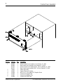
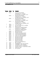
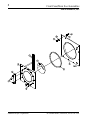
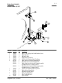
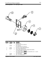
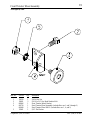
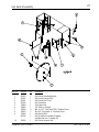
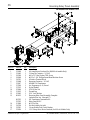
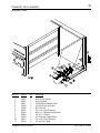
Control Door Assembly
Illus. No. Part No. Qty. Description
1 882093 1 White Control Door Assembly (As of February 11, 1998)
882092 1 Blue Control Door Assembly (As of February 11, 1998)
881732 1 White Control Door Assembly ONLY (Prior to February 11, 1998)
881731 1 Blue Control Door Assembly ONLY (Prior to February 11, 1998)
2 112368 1 Milnor Logo ONLY
3 160005 2 Spring Turn Latch (2-piece)
4 150309 9 #10-16 x 1/2” Hex Head TEK Crimptite Screw
5 102505 1 Control Door Support Rod
6 102601 1 Control Door Retainer Clip
7 102600 1 Control Door Rod Catch

3
Telephone: (508) 678-9000 Fax: (508) 678-9447
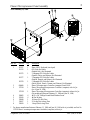
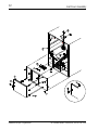
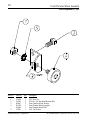
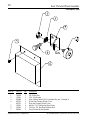
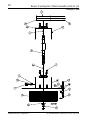
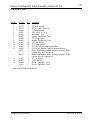
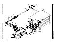
Phase 6 Microprocessor Panel Assembly
Illus. No. Part No. Qty. Description
1 112537 1 Phase 6 OPL Keyboard (touch pad)
112276 1 OPL Stick-On Labels
(English Only) Not Illustrated
112275 1 3 Language OPL Stick-On Labels
(Spanish, Italian, and Hebrew) Not Illustrated
112277 1 3 Language OPL Stick-On Labels
(English, Spanish, and Hebrew) Not Illustrated
112278 1 5 Language OPL Stick-On Labels
(Italian, Dutch, French, German, and Chinese) Not Illustrated
2 824480 1 Phase 6 Microprocessor Controller (computer) Panel ONLY
3 137124 1 Phase 6 Reversing Microprocessor Controller (computer) with Air Jet
(As of June 26, 1998)
137122* 1 Phase 6 Reversing Microprocessor Controller (computer) without Air Jet
(For models mfd. between February 11, 1998 and June 26, 1998)
4 150005 6 #6-32 x 3/4” Phillips Round Head Machine Screw
5 153010 6 #6 Star Washer
6 136048 1 1/8-Amp (Slo Blo) Fuse
7 136017 1 3.5-Amp (Fast Acting) Fuse
8 136019 1 1-Amp (Fast Acting) Fuse
* For dryers manufactured between February 11, 1998 and June 26, 1998 with air jet added, use Part No.
137124 Phase 6 reversing microprocessor controller (computer) with air jet.
As of February 11, 1998

4
American Dryer Corporation 88 Currant Road / Fall River, MA 02720-4781
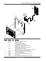
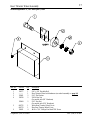
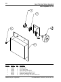
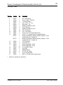
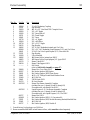
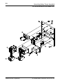
Illus. No. Part No. Qty. Description
1 112537 1 Phase 6 OPL Keyboard (touch pad)
112276 1 OPL Stick-On Labels
(English Only) Not Illustrated
112275 1 3 Language OPL Stick-On Labels
(Spanish, Italian, and Hebrew) Not Illustrated
112277 1 3 Language OPL Stick-On Labels
(English, Spanish, and Hebrew) Not Illustrated
112278 1 5 Language OPL Stick-On Labels
(Italian, Dutch, French, German, and Chinese) Not Illustrated
2 137116 1 Phase 6 Microprocessor Controller (computer)
3 137118 1 Phase 6 OPL Input/Output (I/O) Board, Reversing
4 137121 1 12” Ribbon Cable Assembly
5 150005 6 #6-32 x 3/4” Phillips Round Head Machine Screw
6 153010 6 #6 Star Washer
7 881730 1 Microprocessor Controller (computer) Panel ONLY
Phase 6 Microprocessor Panel Assembly
Prior to February 11, 1998

5
Telephone: (508) 678-9000 Fax: (508) 678-9447
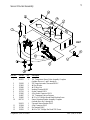
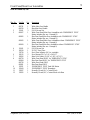
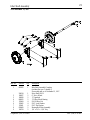
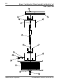
Sensor Bracket Assembly
Illus. No. Part No. Qty. Description
1 880251 1 1/4” Temperature Sensor Probe Assembly Complete
(includes illus. nos. 1 and 5 through 8)
2 130103 1 225º Large Automatic Thermostat ONLY
3 153010 2 #6 Star Washer
4 152000 2 #6-32 Hex Nut
5 121028 2 Insulated Terminal ONLY
6 122701 4 Socket Terminal ONLY
7 122605 1 4-Pin Socket Connector ONLY
8 154007 2 1/4” Tinnerman Push-on Fastener
9 150005 2 #6-32 x 1/4” Phillips Round Head Machine Screw
10 881710 1 Sensor Mounting Bracket Assembly Complete
(includes illus. nos. 1 through 10)
390121 1 Universal Sensor Bracket ONLY
11 122604 1 4-Pin Connector ONLY
12 122700 4 Pin Terminal ONLY
13 150301 2 #8-18 x 7/16” Phillips Pan Head TEK Screw

6
American Dryer Corporation 88 Currant Road / Fall River, MA 02720-4781
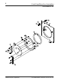
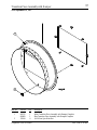
Front Panel/Main Door Assemblies
As of October 24, 1997

7
Telephone: (508) 678-9000 Fax: (508) 678-9447
Illus. No. Part No. Qty. Description
1 881804 1 White Front Panel Assembly
(includes illus. nos. 1, 15, and 16)
For models mfd. as of December 3, 1997
881696 1 White Front Panel Assembly
(includes illus. nos. 1, 15, and 16)
For models mfd. prior to December 3, 1997
881805 1 Blue Front Panel Assembly
(includes illus. nos. 1, 15, and 16)
For models mfd. as of December 3, 1997
881762 1 Blue Front Panel Assembly
(includes illus. nos. 1, 15, and 16)
For models mfd. prior to December 3, 1997
2 102214 1 29-7/8” Door Glass
170730 1 Door Glass Adhesive (10.3 oz. cartridge)
3 102357 1 Main Door Gasket
4 881689 1 White Main Door Assembly Complete
(includes illus. nos. 2 through 10)
881761 1 Blue Main Door Assembly Complete
(includes illus. nos. 2 through 10)
881684 1 White Main Door Ring
881756 1 Blue Main Door Ring
5 881806 6 1/4-20 Free Spin Wash Nut (White)
881807 6 1/4-20 Free Spin Wash Nut (Blue)
6 881740 6 1/4-20 x 5/8” (White) Carriage Bolt
881739 6 1/4-20 x 5/8” (Blue) Carriage Bolt
7 881688 1 White Main Door Handle
881737 1 Blue Main Door Handle
8 881685 1 White Main Door Hinge
881757 1 Blue Main Door Hinge
9 150120 1 Main Door Latch Screw
(#10-32 Dome Hex Head Screw)
10 151010 1 #10-32 Acorn Nut
11 122351 1 “EMERGENCY STOP” Push-Pull Button
12 122419 1 “EMERGENCY STOP” Nameplate
13 132387 1 Normally Closed (N.C.) Contact Block
14 132395 1 Normally Closed (N.C.) Contact Block with Base
15 170330 1 Friction Door Latch
16 154215 2 5/32” Pop Rivet
Front Panel/Main Door Assemblies
As of October 24, 1997

8
American Dryer Corporation 88 Currant Road / Fall River, MA 02720-4781
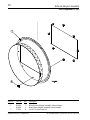
Front Panel/Main Door Assemblies
Prior to October 24, 1997

9
Telephone: (508) 678-9000 Fax: (508) 678-9447
Illus. No. Part No. Qty. Description
1 881741 1 White Main Door Handle
881760 1 Blue Main Door Handle
2 151011 3 5/16-18 Acorn Nut
3 881817 1 White Front Panel/Main Door Assemblies with “EMERGENCY STOP”
Button (includes illus. nos. 1 through 12)
881822 1 Blue Front Panel/Main Door Assemblies with “EMERGENCY STOP”
Button (includes illus. nos. 1 through 12)
881815 1 White Front Panel/Main Door Assemblies without “EMERGENCY STOP”
Button (includes illus. nos. 1 through 8)
881819 1 Blue Front Panel/Main Door Assemblies without “EMERGENCY STOP”
Button (includes illus. nos. 1 through 8)
4 151011 9 5/16-18 Acorn Nut
5 102210 1 20-7/16” Door Glass
170730 1 Door Glass Adhesive (10.3 oz. cartridge)
6 102112 2 Door Magnet (5/16” x 1/4” x 34-3/4”)
7 102356 1 Main Door Gasket (13-1/6” x 1-3/8” x 97-1/2”)
8 881729 1 White Front Panel ONLY for “EMERGENCY STOP”
881824 1 Blue Front Panel ONLY for “EMERGENCY STOP”
881728 1 White Front Panel ONLY
881821 1 Blue Front Panel ONLY
9 122351 1 “EMERGENCY STOP” Push-Pull Button
10 122419 1 “EMERGENCY STOP” Nameplate
11 132387 1 Normally Closed (N.C.) Contact Block
12 132395 1 Normally Closed (N.C.) Contact Block with Base
Front Panel/Main Door Assemblies
Prior to October 24, 1997

10
American Dryer Corporation 88 Currant Road / Fall River, MA 02720-4781
Main Door Switch
Illus. No. Part No. Qty. Description
1 150006 2 #6-32 x 7/8” Phillips Pan Head Machine Screw
2 152013 2 #6-32 Hex Nut
3 153010 2 #6 Star Washer
4 137005 1 Single Pole Door Switch
5 150443 4 1/4-20 x 3/4” Stainless Steel Cap Screw
6 881687 1 White Main Door Switch Housing ONLY
881695 1 Blue Main Door Switch Housing ONLY
881702 1 White Main Door Switch with Housing Assembly
(includes illus. nos. 1 through 4 and 6)
881700 1 Blue Main Door Switch with Housing Assembly
(includes illus. nos. 1 through 4 and 6)
7 150443 2 1/4-20 x 3/4” Stainless Steel Cap Screw
8 881441 1 White Bottom Hinge Block
881735 1 Blue Bottom Hinge Block
9 881440 1 White Top Hinge Block
881736 1 Blue Top Hinge Block
10 153031 1 Nylon Washer
As of October 24, 1997

11
Telephone: (508) 678-9000 Fax: (508) 678-9447
Main Door Switch
Illus. No. Part No. Qty. Description
1 150006 2 #6-32 x 7/8” Phillips Pan Head Machine Screw
2 152013 2 #6-32 Hex Nut
3 153010 2 #6 Star Washer
4 137005 1 Single Pole Door Switch
5 150443 4 1/4-20 x 3/4” Stainless Steel Cap Screw
6 881726 1 White Main Door Switch Housing ONLY
881727 1 Blue Main Door Switch Housing ONLY
881698 1 White Main Door Switch with Housing Assembly
(includes illus. nos. 1 through 4 and 6)
881699 1 Blue Main Door Switch with Housing Assembly
(includes illus. nos. 1 through 4 and 6)
7 150443 2 1/4-20 x 3/4” Stainless Steel Cap Screw
8 881441 1 White Bottom Hinge Block
881735 1 Blue Bottom Hinge Block
9 881440 1 White Top Hinge Block
881736 1 Blue Top Hinge Block
10 153031 1 Nylon Washer
Prior to October 24, 1997

12
American Dryer Corporation 88 Currant Road / Fall River, MA 02720-4781
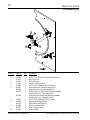
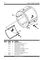
Lint Door Assembly

13
Telephone: (508) 678-9000 Fax: (508) 678-9447
Lint Door Assembly
Illus. No. Part No. Qty. Description
1 882115 1 White Lint Door Assembly ONLY
(includes illus. nos. 1 and 2)
881724 1 White Lint Door and Panel Assembly for models with Knob Latch
(includes illus. nos. 1, 2, and 6)
882114 1 Blue Lint Door Assembly ONLY
(includes illus. nos. 1 and 2)
881811 1 Blue Lint Door and Panel Assembly for models with Knob Latch
(includes illus. nos. 1, 2, and 6)
881725 1 White Lint Door Assembly for models with Door Lock
(includes illus. nos. 1, 2, and 6)
881812 1 Blue Lint Door Assembly for models with Door Lock
(includes illus. nos. 1, 2, and 6)
2 117605 6 1/4” Noise Suppressor Tape (sold by the foot)
3 800150 1 Knob Latch Kit
(includes illus. nos. 3 and 4)
4 160009 1 Lock Cam ONLY
5 160001 1 Lint Door Lock with Key
6 881723 1 White Lint Door Front Panel
881810 1 Blue Lint Door Front Panel
7 150309 11 #10-16 x 1/2” Hex Head TEK Crimptite Screw
8 122116 1 Normally Open (N.O.) Lint Door Switch - 24 VAC
9 300400 1 Lint Door Switch Bracket
10 390136 1 Lint Door Switch Bracket Cover
11 150301 2 #8 x 7/16” Phillips Pan Head TEK Screw
12 --------- 1 Sensor Bracket
(refer to Sensor Bracket Assembly on page 5)
13 824807 1 Rotational Sensor Assembly
14 881734 1 Lint Screen (15-7/8” x 37”) with foam gasket
For models mfd. as of August 22, 1997
881733 1 Lint Screen (16-3/8” x 37”) with foam gasket
For models mfd. prior to August 22, 1997
15 115900 3 Drive Wheel Felt
16 152000 12 Pop Rivet
17 102358 1 Wrapper Gasket

14
American Dryer Corporation 88 Currant Road / Fall River, MA 02720-4781
Basket (Tumbler) Assembly
Illus. No. Part No. Qty. Description
1 882100 4 Basket (Tumbler) Side
170068 4 Stainless Steel Basket (Tumbler) Side
2 881722 1 Basket (Tumbler) Assembly
(includes illus. nos. 1 through 3)
881703 1 Basket (Tumbler)
(includes illus. nos. 2, 4, and 5)
881721 1 Stainless Steel Basket (Tumbler) Assembly
(includes illus. nos. 1 through 3)
881767 1 Stainless Steel Basket (Tumbler)
(includes illus. nos. 2, 4, and 5)
3 150123 40 1/4-20 x 1/4” Socket Button Head Screw
4 102102 1 Rotational Sensor Magnet
5 154200 1 5/32” Pop Rivet

15
Telephone: (508) 678-9000 Fax: (508) 678-9447
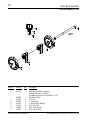
Front Thruster Wheel Assembly
Illus. No. Part No. Qty. Description
1 150220 2 3/8-24 Hex Nut
(for models with 3/8” Hardware)
152004 2 5/16” Hex Nut
(for models with 5/16” Hardware)
2 150501 2 5/16-18 x 3/4” Hex Head Machine Bolt
3 882096 2 Front Thruster Wheel Bracket
4 -------- 2 Front Thruster Wheel Assembly Complete (discontinued)
Use wheel assembly on page 19
-------- 2 Front Thruster Wheel with hardware (includes illus. nos. 1, 4, and 5)
Use wheel assembly on page 19
5 153001 2 5/16” Flat Washer
6 154277 2 5/16” x 3/8” Shoulder Bolt
Between September 15, 1997 and April 6, 1998

16
American Dryer Corporation 88 Currant Road / Fall River, MA 02720-4781
Front Thruster Wheel Assembly
Prior to September 15, 1997
Illus. No. Part No. Qty. Description
1 152004 1 5/16” Hex Nut
2 150501 2 5/16-18 x 3/4” Hex Head Machine Bolt
3 882097 1 Front Thruster Wheel Bracket
4 881758 1 Front Thruster Wheel Assembly
180046 1 Front Thruster Wheel ONLY
5 153001 1 5/16” Flat Washer

17
Telephone: (508) 678-9000 Fax: (508) 678-9447
Rear Thruster Wheel Assembly
Between September 15, 1997 and April 6, 1998
Illus. No. Part No. Qty. Description
1 154277 1 5/16” x 3/8” Shoulder Bolt
2 -------- 1 Rear Thruster Wheel with hardware (use wheel assembly on page 20)
3 153001 2 5/16” Flat Washer
4 150220 2 3/8-24 Hex Nut
(for models with 3/8” Hardware)
152004 2 5/16” Hex Nut
(for models with 5/16” Hardware)
5 881752 1 White Rear Thruster Wheel Cover
881753 1 Blue Rear Thruster Wheel Cover
6 150301 4 #8-18 x 7/16” Phillips Pan Head TEK Screw

18
American Dryer Corporation 88 Currant Road / Fall River, MA 02720-4781
Rear Thruster Wheel Assembly
Prior to September 15, 1997
Illus. No. Part No. Qty. Description
1 152004 1 5/16” Hex Nut
2 153001 1 5/16” Flat Washer
3 180046 1 Rear Thruster Wheel ONLY
4 881752 1 White Rear Thruster Wheel Cover
881753 1 Blue Rear Thruster Wheel Cover
5 150301 4 #8-18 x 7/16” Phillips Pan Head TEK Screw
Page is loading ...
Page is loading ...
Page is loading ...
Page is loading ...
Page is loading ...
Page is loading ...
Page is loading ...
Page is loading ...
Page is loading ...
Page is loading ...
Page is loading ...
Page is loading ...
Page is loading ...
Page is loading ...
Page is loading ...
Page is loading ...
Page is loading ...
Page is loading ...
Page is loading ...
Page is loading ...
Page is loading ...
Page is loading ...
-
 1
1
-
 2
2
-
 3
3
-
 4
4
-
 5
5
-
 6
6
-
 7
7
-
 8
8
-
 9
9
-
 10
10
-
 11
11
-
 12
12
-
 13
13
-
 14
14
-
 15
15
-
 16
16
-
 17
17
-
 18
18
-
 19
19
-
 20
20
-
 21
21
-
 22
22
-
 23
23
-
 24
24
-
 25
25
-
 26
26
-
 27
27
-
 28
28
-
 29
29
-
 30
30
-
 31
31
-
 32
32
-
 33
33
-
 34
34
-
 35
35
-
 36
36
-
 37
37
-
 38
38
-
 39
39
-
 40
40
-
 41
41
-
 42
42


American Dryer Corp. ML-95 Phase 6 User manual
- Type
- User manual
- This manual is also suitable for
Ask a question and I''ll find the answer in the document
Finding information in a document is now easier with AI
Related papers
-
American Dryer Corp. ADG-30DS User manual
-
American Dryer Corp. D30 User manual
-
-
American Dryer Corp. AD-330 User manual
-
-
-
-
-
-
Other documents
-
Hans Grohe 41534XX1 User manual
-
Midmark 6251, 6252, 6256 (Powered Carts - DC) Installation guide
-
 T & S Brass & Bronze Works BL-9005-01 Datasheet
-
GINGER 4781/PC Installation guide
-
ADC AD-15 User manual
-
ADC AD-360X2 User manual
-
ADC ADG-758 User manual
-
-
 T & S Brass & Bronze Works BL-9000-09 Datasheet
-

