Page is loading ...

ML-175
Parts Manual
1999/2001
American Dryer Corporation
88 Currant Road
Fall River, MA 02720-4781
Telephone: (508) 678-9000 / Fax: (508) 678-9447
E-mail: [email protected]
www.amdry.com
122199DMG/tcosta ADC Part No. 450071

ML-175
Retain This Manual In A Safe Place For Future Reference
American Dryer Corporation products embody advanced concepts in engineering, design, and safety. If this product is
properly maintained, it will provide many years of safe, efficient, and trouble free operation.
ONLY qualified technicians should service this equipment.
OBSERVE ALL SAFETY PRECAUTIONS displayed on the equipment or specified in the installation manual included with
the dryer.
The following “FOR YOUR SAFETY” caution must be posted near the dryer in a prominent location.
We have tried to make this manual as complete as possible and hope you will find it useful. ADC reserves the right to make
changes from time to time, without notice or obligation, in prices, specifications, colors, and material, and to change or
discontinue models.
Important
For your convenience, log the following information:
DATE OF PURCHASE ____________________________ MODEL NO. __________________________________________
RESELLER’S NAME _______________________________________________________________________________________
Serial Number(s) ________________________________________________________________________________________
________________________________________________________________________________________
________________________________________________________________________________________
Replacement parts can be obtained from your reseller or the ADC factory. When ordering replacement parts from the factory,
you can FAX your order to ADC at (508) 678-9447 or telephone your order directly to the ADC Parts Department at (508)
678-9000. Please specify the dryer model number and serial number in addition to the description and part number, so that
your order is processed accurately and promptly.
The illustrations on the following pages may not depict your particular dryer exactly. The illustrations are a composite of the
various dryer models. Be sure to check the descriptions of the parts thoroughly before ordering.
“IMPORTANT NOTE TO PURCHASER”
Information must be obtained from your local gas supplier on the instructions
to be followed if the user smells gas. These instructions must be posted in a
prominent location near the dryer.
FOR YOUR SAFETY
Do not store or use gasoline or
other flammable vapors and
liquids in the vicinity of this or
any other appliance.
POUR VOTRE SÉCURITÉ
Ne pas entreposer ni utiliser d’essence
ni d’autres vapeurs ou liquides
inflammables à proximité de cet
appareil ou de tout autre appareil.

Control Door Assembly .......................................................................................................................... 2
Microprocessor Control Panel Assembly................................................................................................. 3
Front Panel Assembly ............................................................................................................................. 4
Cold Rolled Steel (CRS) Main Door Assembly ....................................................................................... 5
Main Door Switch Assembly................................................................................................................... 6
Lint Door Assembly ................................................................................................................................ 7
Lint Drawer/Lint Drawer Switch Box Assemblies
For Models Mfd. as of August 14, 2000 ........................................................................................... 8
Lint Drawer/Lint Drawer Switch Box Assemblies
For Models Mfd. prior to August 14, 2000 Which Have Individual Lint Screen and Drawer............... 9
Fan (Squirrel Cage) Shaft Mount Assembly ........................................................................................... 10
Blower Motor Mount Assembly .............................................................................................................11
Microprocessor Temperature Sensor Bracket Assembly ........................................................................ 12
Basket (Tumbler) Assembly .................................................................................................................. 13
Basket (Tumbler) Bearing/Rotational Sensor Assemblies ........................................................................ 14
Drive Shaft Assembly............................................................................................................................ 15
Idler Shaft Assembly ............................................................................................................................. 16
Speed Reducer Shaft Assembly ............................................................................................................ 17
Totally Enclosed, Non-Venting (T.E.N.V.) Drive Motor Assembly.......................................................... 18
Sail Switch Assembly ............................................................................................................................ 19
Direct Spark Ignition (DSI) Burner Assembly .................................................................................. 20, 21
Hot Surface Ignition (HSI) Burner Assembly ................................................................................... 22, 23
Steam Damper Assembly ................................................................................................................ 24, 25
Top Console Assembly ......................................................................................................................... 26
Pneumatic Valve Assembly
For Gas Models Only ..................................................................................................................... 27
Pneumatic Valve Assembly
For Steam Models Only ................................................................................................................. 28
Air Jet Assembly................................................................................................................................... 29
Microprocessor Reversing Contactor Mounting Panel Assembly
208-240v................................................................................................................................. 30, 31
Microprocessor Reversing Contactor Mounting Panel Assembly
460v and 575v ......................................................................................................................... 32, 33
Back Guard Assemblies .................................................................................................................. 34, 35
Table of Contents

2
American Dryer Corporation 88 Currant Road / Fall River, MA 02720-4781
Illus. No. Part No. Qty. Description
1 882495 1 White Control Door Assembly
(includes illus. nos. 1 through 3)
882493 1 White Control Door ONLY
882496 1 Coral Wrinkle Blue Control Door Assembly
(includes illus. nos. 1 through 3)
882494 1 Coral Wrinkle Blue Control Door ONLY
2 882541 2 Spring Turn Latch (2-piece)
3 117603 5 Noise Suppressor Tape (sold by the foot)
4 150309 9 #10-16 x 1/2” Hex Head TEK Crimptite Screw
5 102603 1 Control Door Support Rod Catch
6 102601 1 Control Door Rod Retainer Clip
7 102505 1 Control Door Support Rod
8 112368 1 Milnor Logo ONLY
Control Door Assembly

3
Telephone: (508) 678-9000 Fax: (508) 678-9447
Illus. No. Part No. Qty. Description
1 112537 1 Phase 6 OPL Keyboard
112276 1 OPL Stick-On Labels
(English Only) ... Not Illustrated
112275 1 3-Language OPL Stick-On Labels
(Spanish, Italian, and Hebrew) ... Not Illustrated
112277 1 3-Language OPL Stick-On Labels
(English, Spanish, and Hebrew) ... Not Illustrated
112278 1 5-Language OPL Stick-On Labels
(Italian, Dutch, French, German, and Chinese) ... Not Illustrated
2 881635 1 Computer Door Complete
(includes illus. nos. 1 through 10)
881633 1 Computer Door ONLY
3 137124 1 Phase 6 OPL Reversing Microprocessor Controller (computer)
with Air Jet ONLY
4 150005 2 #6-32 x 1/4” Phillips Round Head Machine Screw
5 153010 2 #6 Star Washer
6 150000 3 #6-32 x 1/4” Slotted Round Head Machine Screw
7 150309 1 #10-16 x 1/2” Hex Head TEK Crimptite Screw
8 136048 1 1/8-Amp (Slo-Blo) Fuse ONLY
9 136017 1 3.15-Amp Fuse ONLY
10 136019 1 1-Amp Fuse ONLY
Microprocessor Control Panel Assembly

4
American Dryer Corporation 88 Currant Road / Fall River, MA 02720-4781
Illus. No. Part No. Qty. Description
1 -------- 1 Cold Rolled Steel (CRS) Main Door
(refer to Cold Rolled Steel [CRS] Main Door Assembly on page 5)
2 150443 2 1/4-20 x 3/4” Stainless Steel Cap Screw
3 -------- 1 Bottom Hinge Block
(refer to Main Door Switch Assembly on page 6)
4 153031 1 Nylon Washer
5 150443 2 1/4-20 x 3/4” Stainless Steel Cap Screw
6 -------- 1 Top Hinge Block
(refer to Main Door Switch Assembly on page 6)
7 882503 1 White Front Panel ONLY
882504 1 Wrinkle Coral Blue Front Panel ONLY
8 122351 1 Large “EMERGENCY STOP” (E-Stop) Mushroom Head Switch
9 122419 1 “EMERGENCY STOP” (E-Stop) Nameplate
10 -------- 1 Main Door Switch
(refer to Main Door Switch Assembly on page 6)
11 132387 1 Normally Closed Contact Block
12 132395 1 Normally Closed Contact Block with Base
13 170330 1 Friction Door Latch
14 154215 2 5/32” Pop Rivet
15 150317 14 #10-16 x 3/4” TORX Plus Button Head Screw
(for models mfd. as of September 29, 2000)
150318 1 25 IP Stick Fit TORX Plus Bit (must be used to remove P/N 150317)
150311 14 #10-16 x 3/4” Phillips Hex Head Screw
(for models mfd. prior to September 29, 2000)
Front Panel Assembly

5
Telephone: (508) 678-9000 Fax: (508) 678-9447
Cold Rolled Steel (CRS) Main Door Assembly
Illus. No. Part No. Qty. Description
1 881689 1 White Cold Rolled Steel (CRS) Main Door Assembly
(includes illus. nos. 2 through 10)
882292 1 Coral Blue Cold Rolled Steel (CRS) Main Door Assembly
(includes illus. nos. 2 through 10)
881684 1 White Cold Rolled Steel (CRS) Main Door Ring
882305 1 Coral Blue Cold Rolled Steel (CRS) Main Door Ring
2 102214 1 30” Door Glass
170730 1 Door Glass Adhesive (10.3 oz. cartridge)
3 881685 1 White Main Door Hinge
882296 1 Coral Blue Main Door Hinge
4 881740 6 1/4-20 x 5/8” White Carriage Bolt
882294 6 1/4-20 x 5/8” Coral Blue Carriage Bolt
5 881688 1 White Main Door Handle
882295 1 Coral Blue Main Door Handle
6 881806 6 1/4-20 White Free Spin Wash Nut
882293 6 1/4-20 Coral Blue Free Spin Wash Nut
7 152008 1 #10-32 Hex Nut
8 150120 1 Door Latch Screw
9 882411 1 Door Gasket
10 151012 4 #10-32 White Nylon Acorn Nut

6
American Dryer Corporation 88 Currant Road / Fall River, MA 02720-4781
Main Door Switch Assembly
Illus. No. Part No. Qty. Description
1 150006 2 #6-32 x 7/8” Phillips Pan Head Machine Screw
2 152013 2 #6-32 Hex Nut
3 153010 2 #6 Star Washer
4 137005 1 Single-Pole Door Switch
5 150443 4 1/4-20 x 3/4” Stainless Steel Cap Screw
6 881687 1 White Main Door Switch Housing ONLY
882291 1 Coral Wrinkle Blue Main Door Switch Housing ONLY
881702 1 White Main Door Switch with Housing Assembly
(includes illus. nos. 1 through 4 and 6)
882298 1 Coral Wrinkle Blue Main Door Switch Housing Assembly
(includes illus. nos. 1 through 4 and 6)
7 150443 2 1/4-20 x 3/4” Stainless Steel Cap Screw
8 881441 1 White Bottom Hinge Block
882283 1 Coral Wrinkle Blue Bottom Hinge Block
9 881440 1 White Top Hinge Block
882284 1 Coral Wrinkle Blue Top Hinge Block
10 153031 1 Nylon Washer

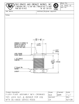
7
Telephone: (508) 678-9000 Fax: (508) 678-9447
Illus. No. Part No. Qty. Description
1 882497 1 White Lint Door Assembly
(includes illus. nos. 1, 2, and 4)
882498 1 Coral Wrinkle Blue Lint Door Assembly
(includes illus. nos. 1, 2, and 4)
2 117607 6 1/4” x 3/8” Poron Foam (sold by the foot)
3 150309 5 #10-16 x 1/2” Hex Head TEK Crimptite Screw
4 117604 9 Neoprene Sponge Tape (sold by the foot)
Lint Door Assembly

8
American Dryer Corporation 88 Currant Road / Fall River, MA 02720-4781
Lint Drawer/Lint Drawer Switch Box Assemblies
Illus. No. Part No. Qty. Description
1 882792 1 White Lint Drawer/Screen Assembly
882793 1 Coral Wrinkle Blue Lint Drawer/Screen Assembly
2 122116 1 Lint Drawer Switch ONLY
3 122605 1 4-Pin Socket Connector
4 122701 2 Socket Terminal ONLY
122801 1 Pin/Socket Extraction Tool
5 882507 1 Lint Drawer Switch Box Assembly Complete
(includes illus. nos. 3 through 6)
6 150301 4 #8-18 x 7/16” Phillips Pan Head TEK Screw
7 122700 2 Pin Terminal ONLY
8 122604 1 4-Pin Connector
9 150301 2 #8-18 x 7/16” Phillips Pan Head TEK Screw
10 319076 1 Right Hand Divider Panel
11 319077 1 Left Hand Divider Panel
12 150301 14 #8-18 x 7/16” Phillips Pan Head TEK Screw
For Models Mfd. as of August 14, 2000

9
Telephone: (508) 678-9000 Fax: (508) 678-9447
Lint Drawer/Lint Drawer Switch Box Assemblies
For Models Mfd. prior to August 14, 2000 Which Have Individual Lint Screen and Drawer
Illus. No. Part No. Qty. Description
1 882449 1 White Lint Drawer ONLY
882450 1 Coral Wrinkle Blue Lint Drawer ONLY
2 108220 1 Lint Screen Assembly ONLY
3 122116 1 Lint Drawer Switch ONLY
4 122605 1 4-Pin Socket Connector
5 122701 2 Socket Terminal ONLY
122801 1 Pin/Socket Extraction Tool
6 882507 1 Lint Drawer Switch Box Assembly Complete
(includes illus. nos. 3 through 6)
7 150301 4 #8-18 x 7/16” Phillips Pan Head TEK Screw
8 122700 2 Pin Terminal ONLY
9 122604 1 4-Pin Connector
10 150301 2 #8-18 x 7/16” Phillips Pan Head TEK Screw
11 319076 1 Right Hand Divider Panel
12 319077 1 Left Hand Divider Panel
13 150301 14 #8-18 x 7/16” Phillips Pan Head TEK Screw

10
American Dryer Corporation 88 Currant Road / Fall River, MA 02720-4781
Illus. No. Part No. Qty. Description
1 100612 1 1-1/4” Bore x 15” Diameter x 6” Blower/Fan (squirrel cage)
2 821078 1 Fan Shaft Mount Assembly Complete
(includes illus. nos. 1 through 16 and 18 through 19)
821073 1 Fan Shaft Mount ONLY
3 117604 4 Neoprene Sponge Tape (sold by the foot)
4 152006 2 1/2-20 Left Hand Jam Nut
5 153065 1 1/2” Flat Washer
6 332280 1 Fan Shaft ONLY
7 881061 1 1-3/8” Flange Bearing with Setscrews and Grease Fitting
8 153004 4 3/8” Flat Washer
9 153005 4 3/8” Lock Washer
10 152005 4 3/8-16 Hex Nut
11 100812 2 1-3/8” Retaining Ring
12 880879 1 1-3/8” Pillow Block Bearing ONLY
13 153004 2 3/8” Flat Washer
14 153005 2 3/8” Lock Washer
15 150617 2 #3-16 x 1” Hex Head Bolt
16 101177 1 2B x 5.8 Pulley (for gas models Only)
17* 100184 2 BX-63 Cogged Belt (fan shaft to blower motor)
For 60 Hz Models ONLY
18 100706 1 5/16” x 5/16” x 1-3/8” Key
19 101194 1 SDS x 1-3/8” Bushing ONLY
* Replace in matched sets (both belts).
Fan (Squirrel Cage) Shaft Mount Assembly

11
Telephone: (508) 678-9000 Fax: (508) 678-9447
Illus. No. Part No. Qty. Description
1 181030* 1 7.5 HP 208-230/460v 3ø 60 Hz Motor ONLY
181031* 1 7.5 HP 200-230/380-410v 3ø 50 Hz Motor ONLY
181039 1 7.5 HP 575v 3ø 60 Hz Motor ONLY
2 101148 1 SB x 4.0 Motor Pulley (60 Hz)
101147 1 SB x 4.8 Motor Pulley (50 Hz)
3 101152 1 SH x 1-3/8” Bushing (60 Hz)
101194 1 SDS x 1-3/8” Bushing (50 Hz)
4 100706 1 5/16” x 5/16” x 1-3/8” Key
5 152004 4 5/16-18 Hex Nut
6 153002 4 5/16” Lock Washer
7 153001 4 5/16” Flat Washer
8 821091 1 Motor Mount Adjustment Plate ONLY
9 153001 4 5/16” Flat Washer
10 153002 4 5/16” Lock Washer
11 150501 4 5/16-18 x 3/4” Hex Head Machine Bolt
12 152004 4 5/16-18 Hex Nut
13 150503 2 5/16-18 x 2” Hex Head Machine Bolt
14 332322 1 Motor Mount Adjustment Angle ONLY
15 153001 2 5/16” Flat Washer
16 153002 2 5/16” Lock Washer
17 150501 2 5/16-18 x 3/4” Hex Head Machine Bolt
18** 100184 2 BX-63 Cogged Belt (matched sets) 50/60 Hz
** 100159 2 BX-61 Cogged Belt (matched sets) 575v 60 Hz ONLY
* Specify voltage when ordering.
** Replace in matched sets (both belts).
Blower Motor Mount Assembly

12
American Dryer Corporation 88 Currant Road / Fall River, MA 02720-4781
Illus. No. Part No. Qty. Description
1 815931 1 Microprocessor Temperature Sensor Bracket Complete
(includes illus. nos. 1 through 10)
820967 1 Microprocessor Temperature Sensor Bracket ONLY
2 150005 2 #6-32 x 1/4” Phillips Round Head Machine Screw
3 153010 2 #6 Star Washer
4 130302 1 225° Manual Reset Thermostat ONLY
5 152000 2 #6-32 Hex Nut
6 121028 2 1/4” x .032 Insulated Terminal
7 122701 4 Socket Terminal ONLY
122801 1 Pin/Socket Extraction Tool
8 122605 1 4-Pin Socket Connector
9 154007 2 1/4” Push On Fastener
10 880251 1 1/4” Temperature Sensor Probe Assembly
(includes illus. nos. 6 through 10)
11 150301 4 #8-18 x 7/16” Phillips Pan Head TEK Screw
Microprocessor Temperature Sensor Bracket Assembly

13
Telephone: (508) 678-9000 Fax: (508) 678-9447
Basket (Tumbler) Assembly
Illus. No. Part No. Qty. Description
1 835269 1 Basket (tumbler) Assembly
(includes illus. nos. 1 through 3)
2 170154 4 Basket (tumbler) Perforated Side
3 150118 48 1/4-20 x 1/4 Socket Button Head Cap Screw
4 881619 1 Rotational Sensor Magnet

14
American Dryer Corporation 88 Currant Road / Fall River, MA 02720-4781
Basket (Tumbler) Bearing/Rotational Sensor Assemblies
Illus. No. Part No. Qty. Description
1 100244 1 1-15/16” Basket (tumbler) Bearing
2 153011 4 9/16” Flat Washer
3 153025 4 9/16” Lock Washer
4 152050 4 9/16-12 Hex Nut
5 319065 1 Rotational Sensor Mounting Bracket
6 815960 1 Rotational Sensor Assembly
7 390314 1 Back Guard ONLY
8 150309 4 #10-16 x 1/2” Hex Head TEK Crimptite Screw
9 100817 1 1-15/16” Retaining Ring

15
Telephone: (508) 678-9000 Fax: (508) 678-9447
Drive Shaft Assembly
Illus. No. Part No. Qty. Description
1 882460 1 Basket (tumbler) Shaft Assembly
(includes illus. nos. 1 and 4)
2 180043 1 11” Drive Wheel
3 101234 1 1-3/8” Taper Lock Bushing
4 ------ 2 1-1/2” Pillow Block Bearing (sold only as part of illus. no. 1)
5 152011 4 3/8-18 Hex Nut
6 153005 4 3/8” Lock Washer
7 153004 4 3/8” Flat Washer
8 835360 2 Bearing Backing Plate Assembly
9 101184 1 1-3/8” Bushing with Setscrew
10 101189 1 2B x 8.0 Pulley
11* 100140 2 BX-38 Cogged Belt
12 100717 1 5/16” x 5/16” x 2-3/4” Key
* Replace in matched sets (both belts).

16
American Dryer Corporation 88 Currant Road / Fall River, MA 02720-4781
Illus. No. Part No. Qty. Description
1 882460 1 Idler Shaft Assembly
(includes illus. nos. 1 and 4)
2 180043 1 11” Drive Wheel
3 101234 1 1-3/8” Taper Lock Bushing
4 ------ 2 1-3/8” Pillow Block Bearing (sold only as part of illus. no. 1)
5 152011 4 3/8-18 Hex Nut
6 153005 4 3/8” Lock Washer
7 153004 4 3/8” Flat Washer
8 835360 2 Bearing Backing Plate Assembly
9 100717 1 5/16” x 5/16” x 2-3/4” Long Key
Idler Shaft Assembly

17
Telephone: (508) 678-9000 Fax: (508) 678-9447
Illus. No. Part No. Qty. Description
1 882505 1 Speed Reducing Shaft Assembly
(includes illus. nos. 1, 3, 4, and 10)
2 101160 1 2B x 3.4 SH Sheave
(for models mfd. as of March 6, 2000)
101187 1 2B x 4.0” Pulley
(for models mfd. prior to March 6, 2000)
3 -------- 1 1-3/8” Bushing with Setscrew (sold only as an assembly, illus. no. 1)
4 -------- 2 1-3/8” Pillow Block Bearing (sold only as an assembly, illus. no. 1)
5 152005 4 3/8-16 Hex Nut
6 153005 4 3/8” Lock Washer
7 153004 4 3/8” Flat Washer
8 835361 2 Bearing Back Up Plate
9 100717 1 5/16” x 5/16” x 2-3/4” Long Key
10 -------- 1 2B x 13.6” SK Sheave
(sold only as an assembly, illus. no. 1)
11* 100124 2 BX-53 Belt
12* 100140 2 BX-38 Cogged Belt
13 101152 1 SH x 1-3/8” Bushing (60 Hz)
(includes illus. no. 9)
14 100717 1 5/16” x 5/16” x 2-3/4” Key
* Replace in matched sets (both belts).
Speed Reducer Shaft Assembly

18
American Dryer Corporation 88 Currant Road / Fall River, MA 02720-4781
Illus. No. Part No. Qty. Description
1 835297 1 Motor Adjustment Plate
2 150501 4 5/16-18 x 3/4” Hex Head Machine Bolt
3 153002 8 5/16” Lock Washer
4 153001 8 5/16” Flat Washer
5 882078 1 3 HP 208-230/380/416/460v 3ø 50/60 Hz Totally Enclosed, Non-Venting
(T.E.N.V.) Motor
181019 1 3 HP 575v 3ø 60 Hz Totally Enclosed, Non-Venting (T.E.N.V.) Motor
6 152004 4 5/16” Hex Nut
7 101235 1 1-1/8” Pulley
8* 100124 2 BX-53 Cogged Belt
9** -------- 1 5/16” Key
10 150619 2 3/8-16 x 3” Tap Bolt
11 152005 4 3/8-16 Hex Nut
* Replace in matched sets (both belts).
** Consult factory.
Totally Enclosed, Non-Venting (T.E.N.V.) Drive Motor Assembly
/