Page is loading ...

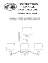
INSTRUCTION MANUAL
PLEASE READ CAREFULLY AND SAVE THESE INSTRUCTION.
SAFETY WARNING
z BE SURE THE ELECTRICITY TO THE WIRES YOU ARE WORKING WITH IS SHUT
OFF; EITHER BY TURNING OFF THE CIRCUIT BREAKER OR BY REMOVING THE
APPROPRIATE FUSE.
z BE CAREFUL NOT TO DAMAGE OR CUT THE WIRE INSULATION (COVERING)
DURING FIXTURE INSTALLATION.
TOOLS YOU MAY NEED
Flathead Screwdriver Phillips Screwdriver Electrical Tape Step Ladder

RE A D & SAVE
INSTA LL ATION & OPERATION INSTRUCTIONS
TOOLS & M ATERI A LS REQUIRED
z Flathead Screwdriver
z Phillips Screwdriver
z Elect rical Tape
z Step Ladder
z Wiring Supplies as required by Electrical Code
C A UTION
Before assembling your Lighting fixture, refer to the
s ection titled “ELE CTRIC A L C ONNECTIO NS”. If
you feel you do not have electrical wiring experience,
refer to a do-it-yourself wiring hand-book or have
your fixture installed by a qualified licensed
electrician.
GENERAL
1. To ensure the success of the installation, be sure
to read the se instructions and review the
diagrams thoroughly before be ginning.
2. All electrical connections must be in accordance
with local codes, ordinances, or the National
Elect ric Code. If you are unfamiliar with
methods of installing elect rical wiring, secure the
s ervices of a qualified licensed electrician.
3. These fixtures are intended to be mounted to a
UL Listed metal or plastic round box. The box
must be directly supported by t he building
structure.
4. Before starting the installation, disconnect the
power by turning off the circuit breaker or by
removing t he appropriate fuse at the fuse box.
Turning the power off using the light switch is
not sufficient to prevent electrical shock.
NOTE: The importa nt safeguards and instructions
appearing in this ma nual are not meant to cover all
possible conditions and situations that may occur. It
must be understood that common sense, caution, and
care are factors which cannot be built into any
product. The se factors must be supplied by the
person(s ) caring for and operating the fixture.
UNPACK THE FIX TURE
Check the contents of the box. You should receive:
z Mounting Hardware Package
z As sembled Fixture
PREPARE THE FIX TURE
NOTE: First turn off electricity
1. If you are replacing an existing fixture,
disconnect and remove the old fixture. Expose
the supply wiring from the outlet box.
2. Snap socket spring into canopy.
3. Attach the grounding wire (green or bare copper)
from the supply circuit to the canopy with
connector provided. Some models have a
grounding wire attached to the fixture. For
models that employ a green or bare copper
grounding wire. It will be necessary to connect
the green or bare grounding wire to the
grounding conductor of the supply circuit.
4. Make electrical connections.
ELECTRICAL CONNECTIONS
Connect the white wire(s) from the fixture to the
white wire of the s upply circuit. Connect the black
wire(s) from the fixture to the black wire of the
supply circ uit. Connect the green (or bare copper)
colored wire to the grounding conductor of the supply
circ uit. Use U. L. Listed wire c onnectors suitable for
the size, type and number of conductors. N O loose
strands or loose wires should be present. Secure wire
connectors with U. L. Listed electrical ta pe.
FIN A L ASSEMBLY
1. Spread the electrical splices so that the black
wires are on one side of the outlet box and the
white wires are on the ot her side.
2. After wires are connected, tuck them carefully
inside outlet box. Raise canopy allowing for
these wires through hole on canopy, and secure
canopy onto outlet box with two outlet box
screw.
3. Place the wa s her, glass over t he nipple in order
and secure the plastic finial into nipple.
4. Install light bulbs (not provided) to the socket.
C A UTION: Refer to the re-lamping label
located near the lamp holder for recommended
maximum wattage-do not exceed recommended
wattage.
5. Restore electricity and check the operation of
your new lighting fixture.
Mounting hardware included:
z 3 Connectors
z 2 Outlet Box Screws
z 1 Plastic Finial
z 1 Washer

MANUAL DE INSTRUCCIONES
LE A DETENIDAMENTE ESTAS INSTRUCCIONES Y GUÁRDELAS.
Advertencia de seguridad
z ASEGÚRESE DE QUE LA ELECTRICIDAD A LOS CABLES CON LOS QUE EST Á
TRA BAJANDO ESTÉ DESCONECTADA; YA SEA APAG ANDO EL DISYUNTOR O
EX TRAYENDO EL FUSIBLE CORRESPONDIENTE.
z PROCURE NO DA ÑAR O CORTAR EL AISL AMIENTO DEL CA BLE ADO (CUBIERTA)
DURANTE LA INSTAL ACIÓN DEL DISPOSITIVO.
HERRAMIENTAS QUE PUEDE NECESITAR
Destornillador de cabeza plana Destornillador Phillips Cinta ais lante Escalera de tijera
/


