Frigidaire FFRS0822S1 Installation guide

Type
Installation guide
READ BEFORE INSTALLING UNIT
For Slider Casement Air Conditioners
1
Installation Instructions
NOTE:
These instructions describe installation in a typical wood framed window with a wood SLIDE-BY sash, or
installation in a metal CASEMENT window. Modification may be necessary when installing in windows made
differently than those shown in these instructions.
WARNING:
Electrical ground is required on this appliance.
Electrical Shock and Personal Injury Hazard
DO NOT ground to a gas line.
If cold water pipe is interrupted by plastic, non-metallic gaskets, or other insulating materials, DO NOT use for
grounding.
Check with a qualified electrician if you are in doubt as to whether the appliance is properly grounded.
DO NOT modify power supply cord plug. If it does not fit outlet, have a proper outlet installed by a qualified
electrician.
DO NOT have a fuse in the neutral or grounding circuit. A fuse in the neutral, or grounding circuit could result in
an electrical shock.
DO NOT use an extension cord with this appliance.
Failure to follow these instructions could result in electrical shock, serious injury, or death.
Meeting Electrical Requirements
OBSERVE ALL LOCAL GOVERNING CODES AND ORDINANCES. DO NOT, UNDER ANY CIRCUMSTANCES,
REMOVE THE POWER SUPPLY CORD GROUNDING PRONG.
NOTE:
If codes permit, and a separate grounding wire is used, it is recommended that a qualified electrician determine
that the grounding path is adequate and not interrupted by plastic, non-metallic gaskets, or other insulating
materials.
2020213A1659
Pay attention to danger and safety notices.
To avoid risk of personal injury, property damage, or product damage due to the weight of this device and sharp edges that may
be exposed:
Air conditioners covered in this manual pose an excessive weight hazard. Two or more people are needed to move and install
the unit. Wear protective gloves whenever lifting or carrying the unit. AVOID the sharp metal fins of front and rear coils. To
prevent injury or strain, use proper lifting and carrying techniques when moving unit.
Carefully inspect location where air conditioner will be installed. Be sure it will support the weight of the unit overan extended
period of time.
Handle air conditioner with care.
Make sure air conditioner does not fall during installation.
Carefully read the installation manual before beginning.
Follow each step as shown.
Observe all local, state, and national electrical codes and by qualified, licensed, authorized personnel only.
INSTALLATION WARNINGS AND CAUTION
2
Installation Instructions
Receptacle Wiring:
Receptacle wiring should be a minimum of 14 gauge. Use copper wire only. It is your responsibility to provide proper
and adequate receptacle wiring, installed by a qualified electrician.
Electrical Requirements:
A 115 volt (103.5 minimum, 126.5 maximum), 60 Hertz, AC only, 15 ampere fused electrical supply is required. A time
delay fuse or time delay circuit breaker is also required. A separate circuit, serving this appliance only, MUST be
provided.
Electrical Connection:
Electrical grounding is required on this appliance.
Recommended grounding method:
For your personal safety, this appliance must be grounded.
This air conditioner includes a power supply cord with a
3-prong grounding plug. To minimize possible electrical shock
hazard:
cord must be plugged into a matching 3-prong grounding type
wall receptacle.
must be grounded in accordance with National Electrical
Code (ANSI/NFPA 70-latest version) and all local codes and
ordinances.
If a matching 3-prong grounding type wall receptacle is not available,
it is the responsibility of the consumer to have a properly grounded
3-prong wall receptacle installed by a qualified electrician.
3-Prong Grounding
Type Wall Receptacle
3-Prong
Grounding plug
Grounding prong
Power Supply Cord
(6 feet long)
Preparing for Installation
Installation Tips
For wood-frame casement windows:
It may be necessary to construct a frame, using at least
1 thick wood, with a 15-1/2 wide opening.
For brick or cement building construction:
It may be necessary to put a wood stool strip under air
conditioner, for mounting purposes as shown FIG. 2.
WARNING:
Because this unit weighs about 60 to 80 pounds, it is recommended that you have someone help you when
installing your new unit, and that you both use proper lifting techniques. Inspect the condition of the window
where unit will be installed. Be sure it will support the weight of the unit.
This appliance must be installed according to all applicable codes and ordinances.
Failure to adhere to the following precautions could result in personal injury and product damage.
Handle air conditioner with care. AVOID sharp metal fins on front and rear coils.
Make sure your air conditioner does not fall during installation.
Do not use water collected in the unit for drinking purposes. It is not sanitary.
Flat-head screwdriver
Phillips-head screwdriver
Tools Required
Carpenter’s level
Tape measure
Fine tooth saw
Electric or hand drill
Knife and scissors
Pencil
NOTE:
DO NOT USE ANY SCREWS OTHER THAN THOSE SPECIFIED IN THESE INSTRUCTIONS.
inner sill
OUTDOORINDOOR
outer sill
Bottom Rail of
air conditioner
wood strip
mounted on
top of inner sill
FIG. 1
FIG. 2
3
Installation Instructions
Make sure you have all the necessary parts.
Installation kit contents (FIG.3):
Hardware
Side channel seal
Support brace
Platform
Adjustment bolt
Hex flange nut - 1/4
Track seal
Window sash seal
Safety bracket
Qty.
1
1
1
1
1
1
1
1
2
1
2
3
4
5
6
7
8
No.
9
Qty.
2
2
6
7
1
1
2
10
1
Hardware
Window locking bracket
Plastic window panel
Side channel
Panel frame/seal assembly
No.
12
11
10
13
14
15
16
17
18
1
Support bracket
(For Vinyl-Clad windows)
19
1
Safety bracket
(For Vinyl-Clad windows)
20
1
2
12
19
17
16
14
4
3
9 or 10
or 11 or 17
13
8
20
5
17
7
15
6
18
NOTE:
Use scale below to measure length of your screws. The scale will come in handy
when separating screws for installation.
IDENTIFY SCREWS
BY LENGTH
(13mm)
(25mm) (44mm) (63mm)
(10mm) (19mm) (38mm) (50mm)
NOTE:
Height measurement must be of a clear opening above mounting platform.
In some cases, due to a variety of stop and track arrangements, the above
dimensions may vary slightly. If necessary, installation can be made by
alternating window jambs. (See Alternate Window Jamb Applications.)
FIG.3
minimum
width
minimum
height
maximum
height
maximum
16-1/4
21-1/2
15-1/2
40
width
(casement
windows)
FIG.4
1
Choose a proper sized window, as shown (FIG.4).
15-1/2 minimum width
16-1/4 maximum width (for casement windows)
21-1/2 minimum height (with window panel retainer)
20-5/16 minimum height (window panel retainer removed)
40 maximum height
2
Choose the proper window location.
Choose a window that allows the cooled air to flow freely and directly into
room(s) you wish to cool. Remember, it is difficult to move air around
corners. Also, choose a window that is within 6 feet of an electrical outlet
as shown (FIG.5). (See Meeting Electrical Requirements/Receptacle wiring
needs.) Do not use an extension cord.
3
6 feet
power cord
reach
FIG.5
Inside wall
of house
Siding-protection
board
Apply track seal
to window side
of track.
FIG.9
FIG.8A
with platform tab pressed
against window track
Center platform
assembly on the line
Attach support brace to platform as shown (FIG.6). Use adjustment
bolt and hex flange nut to complete assembly. Choose slot and adjustment
bolt hole locations that will create a 45 degree angle between platform and
support brace. Try assembly in the window to determine if platform will rest
properly, and allow proper slope (3/16 lower on out side).
4
Center platform assembly on the line with inside platform tab
pressed against inside edge of window track as shown (FIG.8A, FIG.8B).
Using the holes in the platform as a guide, mark and drill two 9/64 diameter
holes. Drill holes in either track or stool.
6
Peel off protective backing from track seal. Apply seal to room side
of window track (FIG.9). Center of seal strip should coincide with the line
marked in Step 5. The two screw holes drilled in Step 6 should be directly
above seal strip in the inner track.
7
Securely attach a siding-protection board to side of house (FIG.10).
NOTE: Siding-protection board should be long enough to span 2 wall studs.
8
4
Installation Instructions
Installing Unit in a Sliding Window:
NOTE:
If you are planning to use a siding-protection board (see Step 8) on the
outside of your house, hold board in place when testing assembly in window.
NOTE:
If any sash stop protrudes more than 1 from the side window jambs, the
8-11/16 measurement must be increased accordingly (FIG.7). Screen and
storm window frames may also require adjustments to the measurement.
For vinyl-clad windows, you need to install the support bracket on the
window track before you install the platform. Follow the instructions below to
do that.
1. Place the support bracket on the window sill as shown (FIG.8C). Using the
holes in the support bracket as a guide, mark and drill two 1/8" diameter holes.
2. Follow Step 7 to applly the track seal on the room side of window track.
3. After applly the track seal, use two 3/8" screw (item 17) to fixing the support
bracket. Make sure the support bracket is level form side to side.
Proceed to Step 9 after you finish fixing the support bracket.
Platform Assembly
FLANGE NUT
1/4 (6mm) HEX
FIG.6
8-11/16 inches FIG.7
window track window seal
Alternate screw location
(depending on the inner sill depth)
Platform tab
FIG.8B
FIG.10
Measure, and lightly mark a line 8-11/16 from window jamb:
5
8-11/16 inches
FIG.8C
Alternate the screw
location (depending on
the height of the sill)
5
Installation Instructions
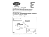
To remove front as shown (FIG.16)
1. Remove the two front retaining screws from the front frame.
2. Press firmly on each side of the metal case close to front, approximately 2/3 of the way down.
3. While pressing on the sides of the metal case, gently pull the front out and lift up to release it from the case.
4. Then release the electrical coupler plug.
Place air conditioner in window opening. As shown (FIG.17), it should sit on platform assembly so that
window panel frame and cabinet side channels are against top and side window jambs.
Outside edge is 3/16
lower than inside.
Put platform
tab against
inside of track.
FIG.11A
Measure
distance
and
subtract
20-5/8
FIG.12
Panel frame
Plastic
window panel
FIG.14
Apply side
channel seal
to side channels
just below edge
of panel frame
FIG.15
NOTE: DO NOT push or pull air direction louvers.
Front
Retaining
Screw
FIG.16
Slide inner
window sash
firmly against
cabinet.
FIG.17
Adjust platform assembly so that outside edge is 3/16 lower than
inside edge, as shown (FIG.11A & FIG.B). This ensures proper water drainage
from the air conditioner.
Level platform assembly from side-to-side. Also, make sure window
track is level. Use leveling shims as necessary to ensure unit is level from
side-to-side.
Measure height of window opening from top of platform assembly as
shown (FIG.12). Subtract 20-5/8. Mark this measurement on plastic window
panel, along the longer side.
Clamp plastic window panel between a board and a work table, and
cut along cutting line with a fine tooth saw. Remove any burrs with a file.
Fasten side channels to the sides of the air conditioner using 3 screws
(Item 17) per channel as shown (FIG.13). Start with first screw at top of
channel. Make sure hook ends of channels face toward back of unit.
Slide plastic window panel into panel frame as shown (FIG.14), with
the smooth side to the room. Slide panel frame assembly into side channels
of the AC cabinet. Make sure plastic window panel is firmly enclosed on all
sides by the retainer grooves.
10
11
12
13
14
15
Cut side channel seal into 2 equal lengths. Remove protective backing
and apply it to the rear side of cabinet side channels, starting just below panel
frame assembly (FIG.15). Pinch off excess length so seal is even with the bottom
of the cabinet side channel.
16
17
18
Place platform assembly, with platform tab against inside of window
track, and attach it to window jamb (FIG.11A). Use appropriate length
screws (Items 9-11 in preparing For Installation).
9
For Vinyl- Clad windows, place platform assembly, with platform tab
against insidh edge of the support bracket, and use two 3/8" screw (item 17)
to attach it to support bracket as shown (FIG.11B).
FIG.11B
Put platform tab
against inside edge
Outside edge is 3/16”
lower than inside.
Fastening
Side Channels
FIG.13
FIG.18
6
Installation Instructions
Slide inner window sash firmly against side of the cabinet. Make sure not to peel the seal strips from the window
track and cabinet side channels. If the panel frame does not fit snugly to the inner window sash, secure the panel frame
to the sash with #8 x 3/4 self-threading screws. Use the partially plugged holes in the panel frame. Drill 1/8 pilot
holes for the screws.
Hook the safety bracket over the base of the unit and fasten it to the front of the platform assembly (FIG.18). Use
a #8-32 x 3/4 self-threading screw.
NOTE: The bracket prevents movement of the air conditioner (either in or out) after completing the installation.
Stuff the window sash seal between the vertical sash and the window glass, as shown (FIG.19).
Use the window locking bracket to lock the inner window sash to the base of the outer window sash (FIG.19).
Use one #8 x 3/4 screw, or #8-32 x 3/4 self-threading screw. (Drill 1/8 pilot hole).
To replace the front first reconnect the coupler plugs, make the exhaust control positioned through the front in
the proper location. Gently push the front into position on the cabinet. It should click into place. Then replace the
retaining screws that holds the panel in place. DO NOT push or pull the front panel louvers.
Insttall safety bracket
window sash seal
Window
locking
bracket
To install in windows having no flanges or wood stops on the top and side jambs, the channels and panel frame must
fit against a matching flange (or 1/16 max. thick angle) attached to the window jambs. FIG.20A shows this angle
installed. FIG.20B & FIG.20C show alternate treatments. On the sash side of the opening, the leading corner of the inner
sash becomes the flange. You can purchase the angle strip locally.
Alternate Window Jamb Applications
FIG.20C
FIG.20A
FIG.20B
Add angle to wood stop Add wood as shown
Add 16- or 18- gage angle
Room
3/4” or 1”
Room
1”x1“ or
3/4”x3/4”
angle
Installing the Unit in a Casement Window
NOTE:
Open the window the maximum amount to allow for clearance of the cabinet.
The crank handle should be removed to allow the platform to be fastened to
the jamb. If the window cannot open far enough (more than 15-1/2) for the
cabinet to clear the window, remove the window entirely by drilling out the
rivets. Bolts can serve as the pivots in the feature.
To avoid crank handle and window clearance problems, the unit can be
installed in a stationary sash section. However, the horizontal mullion and
the 2 glass panels must be removed before installation.
Attach support brace to platform as shown (FIG.21). Use the adjustment bolt
and hex flange nut to complete the assembly. Choose the slot and adjustment bolt
hole location that will create a 45 degree angle between the platform and support
brace. Try the assembly in the window to determine if the platform will rest properly,
and allow the proper slope (3/16 lower on outside).
FIG.19
Room
3/4” or 1”
Flush
Platform Assembly
1/4” (6mm) HEX
FLANGE NUT
FIG.21
19
20
21
22
23
24
safety bracket
(choose the correct
safety bracket
according to your
window type)
For Vinyl-Clad windows, use Item 20 (refer to page 3) to fasten the unit to the platform.
7
Installation Instructions
NOTE:
If you are planning to use a siding-protection board (see Step 29) on the outside of your house, hold the board in
place when testing the assembly in the window.
Equal distance from both sides Apply track seal to the outside
edge of the bottom window jamb.
Track seal
Window jamb
Screw
NOTE:
A projection below the base of the air conditioner will require the rear of the platform to be 7/16” lower than the
front to create the 3/16” slant from front to rear (FIG.25) .
Measure the height of the window opening from the top of the platform
assembly as shown (FIG.27). Subtract 20-5/8. Mark this measurement on the
plastic window panel, along the longer side.
Clamp the plastic window panel between a board and a work table, and
cut along the cutting line with a fine tooth saw. Remove any burrs with a file.
Fasten the side channels to the sides of the unit using three screws
(Item 17) per channel. Make sure hook ends of channels face toward the back
of unit.
Slide the plastic window panel into the panel frame with the smooth
side to the room. Slide the panel frame assembly into the side channels of
the air conditioner cabinet. Make sure the plastic window panel is firmly
enclosed on all sides by the retainer grooves (FIG.28).
FIG.22 FIG.23 FIG.24
Fasten siding
protection board to
the house siding.
Rear is at least
7/16” lower than
front
FIG.25 FIG.26
Measure
distance
and
subtract
20 5/8
FIG.27
Panel frame
Plastic window panel
FIG.28
Drill a 9/64 diameter pilot hole in the window jamb an equal distance from each side of the jamb (FIG.22),
and 3/16 up from the window sill. If the hole coincides with the window lever slot in the jamb bottom, an additional hole
will have to be drilled through the platform edge and the window jamb to miss this slot.
25
Peel off the protective backing from the track seal, and stick the seal to the window sill on the outside of the
bottom jamb as shown (FIG.23).
26
Screw the platform assembly to the window jamb through the pilot hole you drilled in Step 25. Use a #8 x 3/4
self-threading screw (FIG.24).
27
Adjust the platform assembly so that the rear of the air conditioner will be 3/16 lower than the front (tilted about
2° to 4° downward to the outside). After proper installation, condensate should not drain from the overflow drain hole
during normal use, correct the slope otherwise.
28
Securely attach a siding-protection board to the side of the house where the platform assembly hit the house
as shown (FIG.26). The siding-protection board should be long enough to span 2 wall studs.
29
30
31
32
33
9/64 diameter
pilot hole
8
Installation Instructions
Cut side channel seal into 2 equal lengths. Remove the protective backing and apply it to the rear side of the
cabinet side channels, starting just below the panel frame assembly. Pinch off excess length so the seal is even with
the bottom of the cabinet side channel (FIG.29).
To remove front as shown (FIG.30)
1. Remove the two front retaining screws from the front frame.
2. Press firmly on each side of the metal case close to the front, approximately 2/3 of the way down.
3. While pressing on the sides of the metal case, gently pull the front out and lift up to release it from the case.
4. Then release the electrical coupler plug.
NOTE: DO NOT push or pull air direction louvers.
Place the air conditioner in the window opening as shown (FIG.31). It should sit on the platform assembly
so that the window panel frame and the cabinet side channels are against the top and side window jambs. Side
channels should overlap side window jambs equally.
Apply side
channel
seal to side
channels just
below edge of
panel frame.
Front
Retaining
Screw
Drill two 9/64 diameter pilot holes in the top window jamb in line with the partially plugged holes in the panel
frame. Secure the panel frame to the window jamb with two #8-32 x 3/4 self-threading screws. If additional holding is
necessary, two screws may be used on the sides of the panel frame as well.
Drill two screw-clearance holes in the cabinet side channels (near bottom) and two 9/64 diameter pilot holes
in the side window jambs. Secure the cabinet side channels to the window jambs with two #8-32 x 3/4 self-threading
screws. When doing this, be careful not to twist the side channel seals with the screws.
NOTE: Inserting screws will prevent the air conditioner from being pushed into the room.
To replace the front first reconnect the coupler plugs, make the exhaust control positioned through the front
in the proper location. Gently push the front into position on the cabinet. It should click into place. Then replace the
retaining screws that holds the panel in place.
Do not push against or pull upon the front panel louvers.
FIG.29 FIG.30
FIG.31
34
35
36
37
38
39
  • Page 1 1
  • Page 2 2
  • Page 3 3
  • Page 4 4
  • Page 5 5
  • Page 6 6
  • Page 7 7
  • Page 8 8

Frigidaire FFRS0822S1 Installation guide

Type
Installation guide

Ask a question and I''ll find the answer in the document

Finding information in a document is now easier with AI