Page is loading ...

NEW CONSTRUCTION
NuTone Model: 105T (16 volt, 15 watt) transformer must
be purchased separately.
Comply with local and national wiring codes. Bell wire
and pushbuttons(s) will also be needed to complete your
installation. Position the door chime on a wall at eye level.
Handle the chime carefully as you would any precision
i n s t r u m e n t .
W I R I N G
NOTE: Turn the house power off before wiring the
transformer to the junction box.
1. Mount the transformer to a convenient junction box (attic
location is not recommended) or to a circuit breaker box.
Connect the house power leads to the transformer leads -
black to black and white to white.
2. Run two conductor, 18 gauge wire from the transformer
and the pushbutton(s) to the Musical Chime location.
NOTE: When fastening the wiring to the wall studs
and ceiling joists, avoid short circuits that can result
in staples or clips cut through the wiring insulation.
3. Refer to Figure 2. Bring the wires through one of the
large openings in the Musical Chime's baseplate. Fasten
the baseplate to the wall with screws. If the chime is
to be mounted vertically, use the two (2) slotted holes
with T-shaped slots on the top.
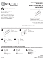
4. Refer to Figure 1. Connect the transformer and
pushbutton wires to the Musical Chime's terminal board.
5. If you plan to use the Musical Chime with a NuTo n e
Radio-Intercom System or an external speaker, follow
the instructions that are provided on page 4 of this sheet
before proceeding with the installation.
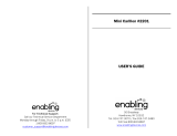
6. Carefully attach the blue, yellow and green wires from
the chime's housing to the lugs marked FRONT, TRANS
and REAR respectively on the terminal block.
7. When the wiring has been completed, snap the chime's
cover onto the baseplate.
8. Reconnect power to the door chime.
TO REGISTER THIS PRODUCT, VISIT WWW.NUTONE.COM
INSTALLATION INSTRUCTIONS
READ AND SAVE THESES INSTRUCTIONS!
Model: LA-52 Series
The chime may be used with lighted or unlighted
pushbuttons. If two lighted pushbuttons are used, use only
pushbuttons that are sold by NuTo n e .
A NuTone Model: 105T (16 volt, 15 watt) transformer must
be purchased separately. N o t e : If desired, an equivalent
transformer may be purchased locally.
NOTE: The Musical Chime features terminals for one-
or two-door operation but cannot be used in multiple
chime installations. Installation of the Chime is
performed in two steps: (1) at the chime site, and (2) at
the front door pushbutton.
EXISTING CONSTRUCTION
If needed, purchase NuTone Model 105T (16 volt, 15 watt)
transformer separately.
Handle the Musical Chime carefully as you would any
precision instrument. Disconnect power to the existing door
c h i m e .
1. Remove the cover from the existing door chime.
2. Disconnect the wires from the terminal strip of the existing
door chime. Mark each wire as it is removed - front,
transformer and rear.
Refer to Figure 1. If any additional wires (i.e. - side
door) are present which are not required by the
wiring diagram, cap these wires individually with a
wire nut and electrical tape.
3. Remove the existing chime base from the wall.
4. Refer to Figure 2. Determine whether the Musical Chime
will be hung vertically or horizontally. Pull the remaining
wires through one of the large holes in the baseplate.
5. Using the proper mounting screws, mount the baseplate
to the wall.
NOTE: If the Musical Chime is replacing a door chime
that was mounted horizontally, the two small round
holes in the base should align with the holes used to
mount the base of the old chime. If the Musical
Chime is replacing a door chime that was mounted
vertically, use the two slotted holes that have
T-shaped slots at the top.
6. Attach wires to the respective screw terminals (FRONT,
TRANS, REAR) that are located on the baseplate's
terminal block.
7. While holding the Musical Chime's housing in one hand,
attach the blue, yellow and green wires from the chime's
housing to the lugs marked FRONT, TRANS and REAR
respectively on the terminal block.
8. If the Musical Chime is to be used with a NuTo n e
Radio-Intercom System or an external speaker, follow
the instructions that are provided on page 3 of this sheet
before proceeding with the installation.
9. When the wiring has been completed, snap the chime's
cover onto the baseplate.
10. Reconnect power to the door chime.
FRONT DOOR
P U S H B U T T O N
18 GA. INSULATED
2 CONDUCTOR WIRE
NUTONE
MODEL 105T
T R A N S F O R M E R
REAR DOOR
P U S H B U T T O N
M U S I C A L
C H I M E
T E R M I N A L
B O A R D
F R O N T
T R A N S
R E A R
FIGURE 1
COMMON WIRES
Musical Door Chime

I N S TA L L I N G T H E P U S H B U T TO N S
A diode must be added to the front door pushbutton
so that power will be supplied continuously to the
Musical Chime while the tune is playing.
The diode is packed inside an envelope that is located
between the baseplate and the chime's housing.
A diode is not required at the back door pushbutton.
To add the diode to the front door's pushbutton:
1. Remove the pushbutton from the door jamb or wall.
2. Refer to Figures 3, 4 and 5. Depending upon which
type of pushbutton is being used, wire the diode to the
two (2) terminals on the pushbutton.
3. Press the front door pushbutton and listen for the
Musical Chime to play.
4. If the tune stops playing as soon as you remove your
finger from the pushbutton, the diode is installed
backwards. Simply reverse the wiring connections
on the pushbutton and test the chime again. The tune
should continue playing even after the pushbutton
is released.
5. Tighten the terminal screws and replace the pushbutton
in the door jamb or wall. Note: on metal siding, place a
small piece of insulating tape on the surface opposite
the diode to prevent shorting.
NOTE: If you are using a lighted pushbutton, the
bulb's brightness will be reduced 30-40%. This is
normal and will increase life of the bulb.
TUNE LABEL
AND TUNE SELECTION
TUNE LABEL
Refer to Figure 6. The tune label is packaged in the same
envelope as the diode.
If the Musical Chime has been mounted in the horizontal
position, tear off and discard the bottom of the label. Peel off
the back and mount the label on the inside surface of the
d o o r .
If the Musical chime has been mounted in the vertical
position, tear the label at both perforations, discard the top
portion and mount the tune list and instructions side by side
on the inside surface of the door.
TUNE SELECTION
The Musical Chime will play 1 of 24 tunes at the front door
and 2 notes of a tune at the rear door.
Refer to the Tune List and to Figure 7. Move the
switches to the desired tune. Example: For "A Bicycle Built
For Two" to be the selected tune, set the switches to "1" "A".
Press the TUNE TEST button. Set the loudness, speed
and pitch of the tune by adjusting the VOLUME, TEMPO and
TONE controls respectively. Turn the controls clockwise to
increase or counterclockwise to decrease.
NOTE: Position 5E does not play a tune. The chime
is in the off position.
H O U S I N G
LOCATE DIODE ENVELOPE
PACKED HERE
Y E L L O W
B L U E
G R E E N
B A S E
FIGURE 2
R E A R
T R A N S
F R O N T
SPKR –
SPKR +
I-COM +
I-COM –
FIGURE 3
FIGURE 5
FIGURE 4
CLIP DIODE LEADS TO
3/8" AND INSERT INTO
T E R M I N A L S
R E C E S S
M O U N T E D
P U S H B U T T O N
WRAP DIODE LEAD
AROUND EACH
TERMINAL SCREW
AND CLIP EXCESS
WRAP DIODE LEAD
AROUND EACH
TERMINAL SCREW
HARMONY MUSICAL CHIME
by NuTone Model LA 5 2
TO SELECT A TUNE
1. Set switches to desired code number and letter.
2. Press TUNE TEST button.
3. Adjust Tone, Tempo and Volume Controls as desired.
4. Press Tune Test to hear again.
TUNE LIST
1 A A Bicycle 5 C In The Good
Built for Two Old Summertime
2 A Battle Hymn 1 D I've Been Working
Of the Republic On The Railroad
3 A D i x i e 2 D Jingle Bells
4 A 1812 Overture 3 D La Cucaracha
5 A For He's A 4 D Oh! Dear, What
Jolly Good Fellow Can The Matter Be?
1 B Frere Jacques 5 D Oh Tannenbaum
2 B Give My 1 E Shave And
Regards To Broadway A Haircut
3 B G r e e n s l e e v e s 2 E Twinkle Twinkle
4 B Hail! Hail! The Little Star
Gangs All Here 3 E Westminster Chimes
5 B Hallelujah Chorus ( 4 - n o t e )
1 C Happy Birthday 4 E Yankee Doodle
2 C Hello, Ma Baby
3 C Home Sweet Home
4 C How Dry I Am
FIGURE 6
R E C E S S
M O U N T E D
P U S H B U T T O N

OPTIONAL FEAT U R E S
USING THE MUSICAL CHIME WITH A NUTO N E
RADIO-INTERCOM SYSTEM
If desired, the Musical Chime may be used with a NuTo n e
Radio-Intercom System. The chime signal will override
the radio-intercom but will not mute the music source.
Refer to the wiring diagram below that corresponds with
the radio-intercom system being used. Connect the wires
(use NuTone IW-2) to the Musical Chime's circuit board
terminals located inside the chime's housing.
To adjust the chime's volume so that it will be heard over
the radio-intercom, use a screwdriver to turn the recessed
control located below the I-COM terminals on the circuit
b o a r d .
USING THE MUSICAL CHIME WITH
AN EXTERNAL SPEAKER
If you do not have a NuTone Radio-Intercom System
but would like for the Musical Chime to be heard in another
section of the home, one external speaker may be used with
the Musical Chime. Note: Speaker must be purchased
separately from NuTo n e .
Use a surface-mounted speaker if the Musical Chime
needs to be heard in another room of the home.
Or, if the Musical Chime needs to be heard at the front
door, use a speaker that includes a pushbutton at that
location. NOTE: If a speaker that incudes a pushbutton
is used, the diode must be added to the pushbutton.
Connect speaker terminals to the Musical Chime's circuit
board at SPKR+ and SPKR– inside the chime's housing.
Polarity need not be considered; connect either of the
speaker's terminals to either SPKR terminal on the Musical
C h i m e .
FIGURE 7
D O O R
P L A C E
L A B E L
H E R E
SELECTOR SWITCHES
SET AT 2D,
"JINGLE BELLS"
T O N E
T E M P O
V O L U M E
E
D
C
B
A
5
4
3
2
1
T U N E
T E S T
CHIME INTERCOM WIRING
MODELS IM-3000,
IM/IMA-4000 OR IM-5000
SERIES
MODEL IM-2003
CHIME
IW-2
IW-2
INTERCOM
MASTER
CHIME
INTERCOM
MASTER
I-COM + WHITE
SPKR –
BLACK
}
C H I M E
I N P U T
I-COM +
INPUT
(COPPER)
(BLUE)
COMMON
(CENTER)
(GREY)
SPKR –
MODEL IMA-516
CHIME
INTERCOM
MASTER
I-COM +
CHIME
I-COM –
CHIME
SPKR –
METAL
CHASSIS
GROUND
SCREW
(RED/WHT
IMA-516)

Product specifications subject to change without notice.
4820 Red Bank Road, Cincinnati, Ohio 45227
Printed in U.S.A., Rev. 01/07, Part No. 84316

I N S TALACION DE LOS BOTO N E S
Hay que añadir un diodo al botón de la puerta principal
para que la corriente sea suministrada de manera
continua al carillón musical mientras está sonando la
m e l o d í a .
El diodo está empaquetado dentro de un sobre ubicado
entre la chapa de montaje y la caja del carillón.
No se requiere un diodo en el botón de la puerta trasera.
Para añadir el diodo al botón de la puerta principal:
1. Retire el botón de la jamba de la puerta o pared.
2. Vea las Figuras 3, 4 y 5. Dependiendo del tipo de botón
utilizado, conecte el diodo a los dos (2) bornes del botón.
3. Pulse el botón de la puerta principal y escuche la melodía
del carillón musical.
4. Si la melodía se detiene tan pronto como deja de apretar
el botón, el diodo está instalado al revés. Simplemente
invierta las conexiones del cableado del botón y pruebe
de nuevo el carillón. La melodía debe de continuar
sonando incluso después de soltar el botón.
5. Apriete los tornillos del borne y cambie el botón de la
jamba de la puerta o pared. N o t a: en las paredes con
forro de chapa metálica ponga un trozo pequeño de
cinta aislante en la superficie opuesta al diodo para
evitar un cortocircuito.
NOTA: Si está utilizando un botón con luz, la
brillantez de la bombilla se reducirá en un 30 ó 40%.
Esto es normal y aumentará la duración de la
b o m b i l l a .
E T I Q U E TA DE LA MELODIA Y
SELECCION DE LA MELODIA
ETIQUETA DE LA MELODIA
Vea la Figura 6. La etiqueta de la melodía está
empaquetada en el mismo sobre que el diodo.
Si ha montado el carillón musical horizontalmente,
desprenda y deseche la parte inferior de la etiqueta. Pele la
parte posterior de la etiqueta y monte esta última en la
superficie interior de la puerta.
Si ha montado el carillón musical verticalmente, desprenda
la etiqueta en ambas perforaciones, deseche la parte superior
de la etiqueta y monte la lista de melodías y las instrucciones
lado con lado en la superficie interior de la puerta.
SELECCION DE LA MELODIA
El carillón musical toca de 1 a 24 melodías en la puerta
principal y 2 notas de una melodía en la puerta trasera.
Vea la lista de melodías y la Figura 7. Cambie los
interruptores a la melodía deseada. Ejemplo: Para
seleccionar la melodía “A Bicycle Built For Two”, ponga los
interruptores en las posiciones “1” “A”.
Pulse el botón de TUNE TEST. Ajuste la sonoridad, la
velocidad y el tono ajustando los controles del VOLUME,
TEMPO Y TONE (volumen, ritmo y tono) respectivamente.
Gire los controles en el sentido de las agujas del reloj para
subir o en el sentido contrario a las agujas del reloj para
bajar.
NOTA: La posición 5E no hace sonar la melodía. El
carillón se encuentra en la posición de apagado.
C A J A
UBIQUE EL SOBRE AQUI
E M P A Q U E T A D O
A M A R I L L O
A Z U L
V E R D E
B A S E
FIGURA 2
T R A S E R A
T R A N S
P R I N C I P A L
SPKR –
SPKR +
I-COM +
I-COM –
FIGURA 3
FIGURA 5
FIGURA 4
RECORTAR LOS
CONDUCTORES DEL
DIODO A 3/8" E
INSERTARLOS EN LOS
B O R N E S
B O T O N
EMBUTIDO
WNROLLAR EL
CONDUCTOR DEL
DIODO ALREDEDOR
DE CADA TORNILLO
DEL BORNEY
RECORTAR EL
E X C E S O
ENROLLAR EL
CONDUCTOR DEL
DIODO ALREDEDOR DE
CADA TORNILLO DEL
B O R N E
HARMONY MUSICAL CHIME
by NuTone Model LA 5 2
TO SELECT A TUNE
1. Set switches to desired code number and letter.
2. Press TUNE TEST button.
3. Adjust Tone, Tempo and Volume Controls as desired.
4. Press Tune Test to hear again.
TUNE LIST
1 A A Bicycle 5 C In The Good
Built for Two Old Summertime
2 A Battle Hymn 1 D I've Been Working
Of the Republic On The Railroad
3 A D i x i e 2 D Jingle Bells
4 A 1812 Overture 3 D La Cucaracha
5 A For He's A 4 D Oh! Dear, What
Jolly Good Fellow Can The Matter Be?
1 B Frere Jacques 5 D Oh Tannenbaum
2 B Give My 1 E Shave And
Regards To Broadway A Haircut
3 B G r e e n s l e e v e s 2 E Twinkle Twinkle
4 B Hail! Hail! The Little Star
Gangs All Here 3 E Westminster Chimes
5 B Hallelujah Chorus ( 4 - n o t e )
1 C Happy Birthday 4 E Yankee Doodle
2 C Hello, Ma Baby
3 C Home Sweet Home
4 C How Dry I Am
FIGURA 6
B O T O N
E M B U T I D O
/