Page is loading ...

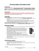
6. Ejecting 9555 Handset
To remove the
9555 handset
from the cradle
FIRMLY press
the “Eject” button
located on the
top of the cradle
(see diagram).
QUICK START GUIDE
iridium SatDOCK 9555
Suitable for the
Iridium 9555 Portable Satellite Telephone
Beam Communications Pty Ltd
5. Inserting 9555 Handset
1. Remove rubber grommet on back of 9555 antenna connection
2. Ensure 9555 handset is turned off
3. Ensure there is no foreign object in the cradle
4. Place the 9555 in the cradle with the base in rst
5. The base connector should line up with the base of the 9555
6. Gently push the face of the 9555 into the SatDOCK
7. The 9555 should click into the locked position
7. Using SatDOCK 9555
• After turning key/Acc on, the SatDOCK will beep upon power up
• Wait for phone to power up and register
• To call, dial the number on the 9555 keypad
• Audio/Mic will automatically route through the HFI unit
• The volume of the call can be increased using the 9555 volume
• The call can be muted using the Mute button on the SatDOCK
• When Mute is ON the Red LED will illuminate
• Incoming calls will ring with a xed tone via the speaker
• (See User Manual to adjust the ring volume)
• Incoming calls answered by pressing green key on 9555
Speaker
MIC
Speaker
MIC
Installing Speaker:
• Mount the speaker underneath the seat or other location that
avoids the speaker facing the microphone
• If feedback occurs upon testing try redirecting the speaker or
locate in another location.
4. MIC / Audio Connections
Connecting Microphone:
• The microphone should be connected to the HFI and then recessed
up the door pillar or similar to a head height location close to the
driver
• Care should be taken to avoid wind or high noise environments
• Avoid crimping or damaging the microphone cable during installation
3. Ensure to
‘click’ to lock
position
8. Optional Handset Modes
Intelligent User Handset: (Fully featured)
• The Beam RST970 Intelligent Handset can be used with
SatDOCK using the RJ45 connector on the HFI unit. The
SatDOCK must be restarted to use this handset.
Compact Privacy Handset: (Side-Jack Mic / Audio Mode)
• The compact handset can be simply used with the SatDOCK
by connecting to the Side-Jack of the 9555 where a portable
hands-free connect.
NOTE: To activate the Side-Jack mode, depress the Mute button
for 1.5 seconds, the LED will ash Orange indicating the Side-
Jack Mode is active. Press again to return to normal hands free
mode.
www.beamcommunications.com
TEL: +61 3 8588 4500
FAX: +61 3 9560 9055
1. Place 9555 on
the base of the
cradle
2. Push 9555
Phone into the
SatDOCK
2. Release the
phone
1. Firmly press
‘Eject’ Button
Click

1. Installing SatDOCK Cradle
3. Afx other base
to SatDOCK with
M4 screws
5. SatDOCK is
now ready to be
wired in
2. Mount base
plate in desired
location
1. Remove base
plates by
loosening wing
nut
Considerations:
• Ensure that the cables will reach from the SatDOCK to the HFI
• Afx the base plate in a location that allows easy access & does not obstruct driver
• Allow sufcient room to easily run cables from theSatDOCK
• ONLY use the M4 screws (supplied) to afx the base to the SatDOCK to avoid any damage
• For wall mounting use the RAM Bracket with both bases parallel to each other
• Tighten wing nut on the bracket to securely hold the SatDOCK
• Avoid making any sharp bends in the antenna cable when determining the cable route
• The xed cables from the SatDOCK should never be extended, Antenna cables must be
approved
2. Connecting SatDOCK
Connecting to Hands-free Interface:
• DC power should not be connected to the HFI before
connecting SatDOCK cables
• It is not safe to extend the main loom from the SatDOCK to
the HFI
• DO NOT route cables near areas of intense heat
• DO NOT pull or strain the cable from the SatDOCK to the HFI
• DO NOT over tighten thumbscrews of HFI connector
Connecting to the Antenna:
• The SatDOCK has a xed antenna y lead ready for
connecting to an antenna cable
• Only certied cables within the Iridium specication should
be used
• Ensure antenna cables are routed avoiding any sharp bends
in the cable
• The antenna should always be installed with clear line of site
to the sky
SatDOCK USB Data Port:
• The SatDOCK has an integrated USB Data Port on the rear.
Download driver from www.beamcommunications.com/sup-
port before use
3. Hands-free Interface
Installation & Connections
Connecting to DC Voltage:
• Secure the HFI through the screw holes on the enclosure and
ensure that all cables connectors are still accessible.
• The HFI can be connected to a 10-32V DC input > 25 watts
• Using the screw connectors provided connect the wires in the
following order from left (1) to right (5)
1. RED = +9 to +32V DC (B+) battery wire to vehicle power via
3A fuse
2. GREEN = ACC Power Sense (+) via 1A Fuse - Ignition Sense
3. BLUE = Horn Alert (wire not included)
4. PINK = Radio Mute (wire not included)
5. BLACK = Ground (B-) Ground Wire to negative battery /
Vehicle Chassis
NOTE: To limit ground loops run the red and black wires directly
to the battery or main power source. Remove ALL fuses before
connecting wires, once complete then reinstall fuses.
ACC Power Sense:
• Automatically senses when the vehicle key is ON and
accessory power present
• If ACC is not available then this ACC wire must be connected
to constant power
USB Data Port
To Iridium
Antenna
SMA -
Hands-free
Interface
+
-
DC Input
10 - 32V DC
DPL
Handset
(Optional)
Speaker
MIC
Horn
100mA max
O/C sink to
ground (use relay)
Accessory Power
(must be connected to
permanent B+ if ACC
power is unavailable)
Radio Mute
100mA max
O/C sink to
ground
Line In/Out (Optional)
Serial Data Port
(D9 com DCE)
Power
LED
O
F
F
A
C
C
SatDOCK 9555 Installation Set Up
1A Fuse
10A Fuse
(Optional)
3A Fuse
6. For wall
mounting use
bases at right
angles
4. Rejoin the two
bases using the
arm
WARNING: Your Iridium 9555 Handset requires
rmware HT09007 or greater. To check your rmware
version on your Iridium 9555 handset press “Menu” then
navigate to “Setup” then “Phone Information”.
For more information and 9555 Handset rmware downloads
visit:
http://www.beamcommunications.com/9555upgrade
NOTE: For Data operation the USB port on the
Iridium 9555 handset must not be used whilst docked in the
cradle. Please use the USB port located on the bottom of the
9555 SatDOCK.
/


