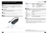
Dell Networking W-IAP205H Instant Access Point
Installation Guide
The Dell Networking W-IAP205H Instant access point is a high-performance dual-
radio wired and wireless Instant access point for hospitality and branch deployments.
This device combines high-performance wireless mobility with Gigabit wired local
access to deliver secure network access to dormitories, hotel rooms, classrooms,
medical clinics, and multi-tenant environments. MIMO (Multiple-Input, Multiple-
Output) technology enables the W-IAP205H access point to provide wireless 2.4
GHz 802.11n and 5 GHz 802.11 n/ac functionality, while simultaneously supporting
existing 802.11a/b/g wireless services.
The W-IAP205H access point can be attached to a wall box using the mounting
bracket provided, or converted into a desk-mounted remote access point for branch
office deployments using the AP-205H-MNTR desk mount kit (sold separately).
The W-IAP205H access point works in conjunction with a built-in virtual controller
and provides the following capabilities:
Dual wireless transceivers
IEEE 802.11a/b/g/n/ac operation as a wireless access point
IEEE 802.11a/b/g/n/ac operation as a wireless air monitor, spectrum analyzer
Supports PoE-in on E0 port (only), and PoE-out on E3 port (only)
Compatibility with IEEE 802.3af/at PoE
Support for selected USB peripherals
Package Contents
W-IAP205H Access Point
Single Gang Wall-box Mounting Bracket
2x #6-32 Machine Screw
T8H Torx Security Screw
Instant Quick Start Guide
Regulatory Compliance and Safety Information Guide
Installation Guide (this document)
Hardware Overview
Figure 1
Front View
LED
The W-IAP205H access point is equipped with two LEDs indicating System Status
and Power Sourcing Equipment (PSE).
Console Port
The W-IAP205H access point is equipped with a serial console port at the
back(
Figure 2). The port allows connecting the AP to a serial terminal or a laptop for
direct local management. The 4-pin connector with removable dust cover is located
on the back of the access point. An optional serial adapter cable (AP-CBL-SER)
compatible with the W-IAP205H access point can be purchased separately.
Figure 2
Back View
Ethernet Ports
The W-IAP205H access point is equipped with a total of four active Ethernet ports
(E0-E3).
The E0 port, located at the bac k of the AP Figure 2 is 10/100/1000 Base-T (RJ-45)
auto-sensing, MDI/MDX wired-network uplink connectivity port. It supports IEEE
802.3af/802.3at Power over Ethernet (PoE), accepting 48VDC (nomial) as a standard
defined Powered Device (PD) from a Power Sourcing Equipment (PSE), such as a
midspan injector or network infrastructure that supports PoE.
The E1-E3 ports, located at the bottom of the AP (Figure 3), are 10/100/1000 Base-T
(RJ-45) auto-sensing, MDI/MDX wired-network downlink connectivity ports. They
are used to provide secure network connectivity to wired devices. Only the E3 port
supports PoE-out functionality, supplying a maximum power of 10W when the AP is
operating in 802.3at PoE mode.
Additionally, the W-IAP205H access point has a Pass-Through (PT) port at the back
(Figure 2) and an E0/PT port at the bottom (Figure 3). The E0/PT port acts
primarily as a Pass-Through (PT) port. Alternatively, the E0/PT port can serve as an
E0 uplink port and accepts 802.3af/802.3at PoE power when the E0 and PT ports at
the back of the AP are physically bridged by an Ethernet cable (AP-CBL-ETH10 sold
separately with the AP-205H-MNTR desk mount kit).
Figure 3
Bottom View
Figure 4
Gigabit Ethernet Port Pin-Out
USB Port
The W-IAP205H access point is equipped with a USB port that is compatible with
cellular modems and Bluetooth Low Energy (BLE) dongles. When the access point is
powered by a DC or 802.3at source, the USB port is enabled allowing an output of up
to 5W
.
Push Button
The push button located on the side of the W-IAP205H access point can be used to
reset the AP to factory default settings or turn off/on the LED display.
To reset the AP to factory default settings:
1. Power off the AP.
2. Press and hold the push button using a small, narrow object, such as a
paperclip.
3. Power-on the AP without releasing the push button. The system status LED
will flash within 5 seconds.
4. Release the push button.
The system status LED will flash again within 15 seconds indicating that the
reset is completed. The AP will now continue to boot with the factory default
settings.
To turn off/on the system status LED:
During the normal operation of the AP, press the push button using a small,
narrow object, such as a paperclip. The system status LED will be turned off/on
immediately.
Power
The W-IAP205H access point has a single 48VDC power connector to support
powering through an AC-to-DC power adapter. AP-AC-48V36 adapter (sold
separately).
The W-IAP205H access point supports both PoE-in and PoE-out functionality. The
PoE-in (PoE-PD) allows the E0 port to draw power from an 802.3at (preferred) or
802.3af (optional) sources.
Additionally, the PoE-out (PoE-PSE) functionality is enabled on the port 3, allowing
a maximum output of 10W. If a device attempts to exceed the 10W power limit, the
E3 port is temporarily disabled. The port will automatically reactivates after being
disabled.
When powered by an 802.3at source, the W-IAP205H access point is able to supply
power to PoE-PSE or USB, but not both simultaneously. The default setting for this
device is PoE-PSE off, USB on. This setting can be configured in Dell Instant.
When powered by an 802.3af source, power sourcing for PoE-PSE and USB is
disabled.
Before You Begin
Pre-Installation Network Requirements
Pre-Installation Checklist
Before installing your W-IAP205H access point, be sure that you have the following:
Cat5E UTP cable with network access installed in the wall box
One of the following power sources:
IEEE 802.3af-compliant Power over Ethernet (PoE) source
Dell AP AC-to-DC adapter kit (sold separately)
Summary of the Setup Process
Complete each of tasks below in the order listed to setup your W-IAP205H access
point.
1. Identify the specific installation location for each AP.
2. Install each AP.
3. Verify post-installation connectivity.
4. Configure the virtual controller. Refer to the Dell Networking W-Series Instant
Quick Start Guide
.
NOTE: The W-IAP205H access point requires Dell Instant 4.2 or later.
NOTE: Inform your supplier if there are any incorrect, missing, or
damaged parts. If possible, retain the carton, including the original
packing materials. Use these materials to repack and return the unit
to the supplier if needed.
LED Color/State Meaning
System Status Off AP powered off, or LED switched to ‘off mode’
Amber- Solid AP ready, restricted mode:
10/100Mbps uplink negotiated
Either radio in non-HT mode
Virtual AP not enabled
Amber- Flashing AP in Air Monitor or Spectrum Analyzer mode
Red Error condition
Green - Flashing AP booting, not ready
Green - Solid AP ready
PSE Off AP powered off, or PoE capability disabled
Green - Solid PoE power enabled
Red PoE power sourcing error or overload
condition
CAUTION: The back panel of this device may become hot after extended use.
ATTENTION: Le panneau arrière du point d'accès AP peut chauffer après une
utilisation prolongée.
NOTE: Hot-plug operation is not recommended for the console port.
Power Source Restrictions USB PoE-PSE
DC (AP-AC-48V36) None (USB and PoE-PSE enabled) 5W 15.4W
802.3at USB or PoE-PSE enabled 5W 10W
802.3af USB and PoE-PSE disabled N/A N/A
NOTE: If both PoE and DC power are available, the AP will default to using
DC power.
CAUTION: FCC Statement: Improper termination of access points installed in the
United States (non-US Regulatory Domain model) will be in violation of the FCC
grant of equipment authorization. Any such willful or intentional violation may
result in a requirement by the FCC for immediate termination of operation and may
be subject to forfeiture (47 CFR 1.80).
ATTENTION: Déclaration FCC: l'arrêt incorrect des points d'accès installés aux
États-unis qui sont configurés sur des contrôleurs autres que le modèle agréé aux
États-unis est considéré comme contrevenant à l'homologation fcc. toute violation
délibérée ou intentionnelle de cette condition peut entraîner une injonction d'arrêt
immédiat de son utilisation par la fcc et peut déboucher sur la confiscation de
l'équipement (47 cfr 1.80).
CAUTION: EU Statement:
Lower power radio LAN product operating in 2.4 GHz and 5 GHz bands. Please
refer to the
Dell Networking W-Series Instant User Guide
for details on
restrictions.
Produit réseau local radio basse puissance operant dans la bande fréquence 2.4
GHz et 5 GHz. Merci de vous referrer au
Dell Networking W-Series Instant User
Guide
pour les details des restrictions.
Low Power FunkLAN Produkt, das im 2.4 GHz und im 5 GHz Band arbeitet. Weitere
Informationen bezlüglich Einschränkungen finden Sie im
Dell Networking W-
Series Instant User Guide.
Apparati Radio LAN a bassa Potenza, operanti a 2.4 GHz e 5 GHz. Fare riferimento
alla
Dell Networking W-Series Instant User Guide
per avere informazioni
detagliate sulle restrizioni.
NOTE: Dell, in compliance with governmental requirements, has designed
the W-IAP205H access point so that only authorized network
administrators can change the settings. For more information about AP
configuration, refer to the
Dell Networking W-Series Instant Quick Start
Guide
and
Dell Networking Instant User Guide
.
CAUTION: Access points are radio transmission devices and as such are subject
to governmental regulation. Network administrators responsible for the
configuration and operation of access points must comply with local broadcast
regulations. Specifically, access points must use channel assignments
appropriate to the location in which the access point will be used.
ATTENTION: Les points d'accès sont des périphériques de transmission radio et
sont, en tant que tels, soumis aux réglementations nationales. Les administrateurs
réseau responsables de la configuration et de l'exploitation des points d'accès
doivent se conformer aux règlements locaux de diffusion. De façon plus précise,
les points d'accès doivent employer des canaux adaptés à leur emplacement
physique