ESAB 200 ULTRA-CUT™ Plasma Cutting System User manual
- Category
- Welding System
- Type
- User manual

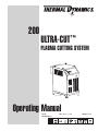
PLASMA CUTTING SYSTEM
200
ULTRA-CUT
™
Operating Manual
Rev. AD Date: February 5, 2008 Manual # 0-5056
Operating Features:
Art # A-04816

WE APPRECIATE YOUR BUSINESS!
Congratulations on your new Thermal Dynamics product. We are
proud to have you as our customer and will strive to provide you
with the best service and reliability in the industry. This product is
backed by our extensive warranty and world-wide service network.
To locate your nearest distributor or service agency call 1-800-
426-1888, or visit us on the web at www.thermal-dynamics.com.
This Operating Manual has been designed to instruct you on the
correct use and operation of your Thermal Dynamics product.
Your satisfaction with this product and its safe operation is our
ultimate concern. Therefore please take the time to read the entire
manual, especially the Safety Precautions. They will help you to
avoid potential hazards that may exist when working with this
product.
YOU ARE IN GOOD COMPANY!
The Brand of Choice for Contractors and Fabricators Worldwide.
Thermal Dynamics is a Global Brand of manual and automation
Plasma Cutting Products for Thermadyne Industries Inc.
We distinguish ourselves from our competition through market-
leading, dependable products that have stood the test of time.
We pride ourselves on technical innovation, competitive prices,
excellent delivery, superior customer service and technical
support, together with excellence in sales and marketing expertise.
Above all, we are committed to developing technologically
advanced products to achieve a safer working environment within
the welding industry.

!
WARNINGS
Read and understand this entire Manual and your employer’s safety practices before
installing, operating, or servicing the equipment.
While the information contained in this Manual represents the Manufacturer's best judge-
ment, the Manufacturer assumes no liability for its use.
Plasma Cutting Power Supply, Ultra-Cut
®
200
Operting Manual No. 0-5056
Published by:
Thermadyne Corporation
82 Benning Street
West Lebanon, New Hampshire, USA 03784
(603) 298-5711
www.thermal-dynamics.com
© Copyright 2007, 2008 by
Thermadyne Corporation
All rights reserved.
Reproduction of this work, in whole or in part, without written per-
mission of the publisher is prohibited.
The publisher does not assume and hereby disclaims any liability to
any party for any loss or damage caused by any error or omission
in this Manual, whether such error results from negligence, acci-
dent, or any other cause.
Printed in the United States of America
Licensed under U. S. Patent No. 5,070,227
Publication Date: February 5, 2008
Record the following information for Warranty purposes:
Where Purchased: ___________________________________
Purchase Date:______________________________________
Power Supply Serial #:_______________________________
Torch Serial #:_____________________________________

This page intentionally blank

TABLE OF CONTENTS
SECTION 1:
GENERAL INFORMATION ................................................................................................ 1-1
1.01 Notes, Cautions and Warnings ...................................................................... 1-1
1.02 Important Safety Precautions ....................................................................... 1-1
1.03 Publications .................................................................................................. 1-3
1.04 Declaration of Conformity ............................................................................. 1-5
1.05 Statement of Warranty .................................................................................. 1-6
SECTION 2: SPECIFICATIONS ................................................................................................. 2-1
2.01 General Description Of The System .............................................................. 2-1
2.02 Plasma Power Supply ................................................................................... 2-1
2.03 Remote Arc Starter ...................................................................................... 2-1
2.04 Gas Control Module ...................................................................................... 2-1
2.05 Precision Plasma Cutting Torch .................................................................... 2-1
2.06 Specifications & Electrical Requirements ..................................................... 2-2
2.07 System Component Layout .......................................................................... 2-2
2.08 Power Supply Dimensions ............................................................................ 2-3
2.09 Power Supply Rear Panel Features ............................................................... 2-4
2.10 Gas Requirements ........................................................................................ 2-5
2.11 Gas Applications .......................................................................................... 2-5
2.12 XTTM-300 Torch Specifications .................................................................... 2-6
SECTION 3: INSTALLATION ...................................................................................................... 3-1
3.01 Installation Requirements ............................................................................. 3-1
3.02 System Layout ............................................................................................. 3-2
3.03 Cables & Leads Identification ....................................................................... 3-3
3.04 Lift the Power Supply .................................................................................... 3-4
3.05 Remove the Connections Cover ................................................................... 3-5
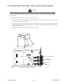
3.06 Ground Connections .................................................................................... 3-10
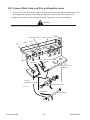
3.07 Connect Work Cable and Pilot and Negative Leads...................................... 3-12
3.08 Connect Coolant Leads ................................................................................3-13
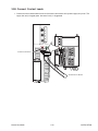
3.09 Connect Control Cables for CNC, Remote Arc Starter, and GCM ................. 3-14
3.10 Connect Fiber Optic Cable (Type 2 internal control module) ........................3-15
3.11 Set Switches on the Command - Control Module (Type 2 Module) ...............3-16
3.12 Height Control Connections ......................................................................... 3-18
3.13 Gas Control Module Installation ................................................................... 3-19
3.14 Fiber Optic Cable Installation ....................................................................... 3-21
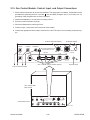
3.15 Gas Control Module: Control, Input, and Output Connections....................... 3-23
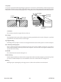
3.16 Install Remote Arc Starter ........................................................................... 3-24
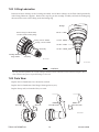
3.17 Original & XTL Torch Valve Installation......................................................... 3-33
3.18 Connecting Torch .........................................................................................3-35
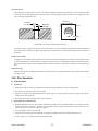
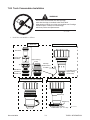
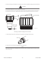
3.19 Install Consumable Torch Parts.................................................................... 3-37
3.20 Complete the Installation .............................................................................3-41

TABLE OF CONTENTS (continued)
SECTION 4: OPERATION .......................................................................................................... 4-1
4.01 Power Supply Control Panel .......................................................................... 4-1
4.02 Start-Up Sequence ....................................................................................... 4-2
4.03 Gas Control Module Operation ...................................................................... 4-3
4.04 Sequence Of Operation ................................................................................ 4-7
4.05 Gas Selection ............................................................................................... 4-9
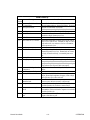
4.06 Power Supply Status Codes ........................................................................ 4-10
4.07 Remote Arc Starter: Service Chart ............................................................. 4-14
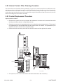
4.08 Remote Arc Starter: Spark Gap Adjustment ............................................... 4-15
SECTION 5: MAINTENANCE .................................................................................................... 5-1
5.01 Periodic Checks ............................................................................................ 5-1
5.02External Coolant Filter Cleaning Procedure .................................................... 5-1
5.03 Internal Coolant Filter Cleaning Procedure .................................................... 5-2
5.04 Coolant Replacement Procedure ................................................................... 5-2
SECTION 6: REPLACEMENT ASSEMBLIES & PARTS ........................................................... 6-1
6.01 Main Component / System Replacement ...................................................... 6-1
6.02 System Layout ............................................................................................. 6-2
6.03 Leads and Cables ......................................................................................... 6-3
6.04 Recommended Gas Supply Hose ................................................................. 6-3
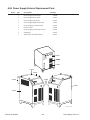
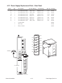
6.05 Power Supply External Replacement Parts ................................................... 6-8
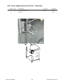
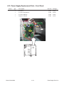
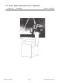
6.06 Power Supply Replacement Parts - Right Side ............................................. 6-9
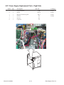
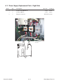
6.07 Power Supply Replacement Parts - Right Side ............................................ 6-10
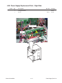
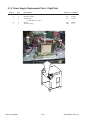
6.08 Power Supply Replacement Parts - Right Side ............................................ 6-11
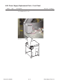
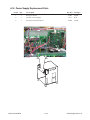
6.09 Power Supply Replacement Parts - Front Panel ........................................... 6-12
6.10 Power Supply Replacement Parts - Front Panel ........................................... 6-13
6.11 Power Supply Replacement Parts - Right Side ............................................ 6-14
6.12 Power Supply Replacement Parts - Rear Panel ............................................ 6-15
6.13 Power Supply Replacement Parts - Right Side ............................................ 6-16
6.14 Power Supply Replacement Parts ................................................................ 6-17
6.15 Power Supply Replacement Parts - Right Side ............................................ 6-18
6.16 Power Supply Replacement Parts ................................................................ 6-19
6.17 Power Supply Replacement Parts - Right Side ............................................ 6-20
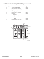
6.18 Gas Control Module (GCM-2010) Replacement Parts ..................................6-21
6.19 Gas Control Module (GCM-2010) Replacement Parts ..................................6-22
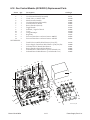
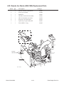
6.20 Remote Arc Starter (RAS-1000) Replacement Parts .................................... 6-23
6.21 Remote Arc Starter (RAS-1000) Replacement Parts .................................... 6-24
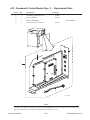
6.22 Command & Control Module Type 2 - Replacement Parts ......................... 6-25
6.23 XTL Torch Valve Assembly External Replacement Parts .............................6-26
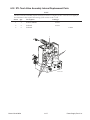
6.24 XTL Torch Valve Assembly Internal Replacement Parts ............................... 6-27
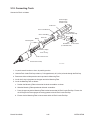
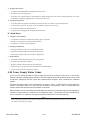
SECTION 7: TORCH MAINTENANCE.................................................................................... 7-1
7.01 Consumable Removal ................................................................................... 7-1
7.02 O-Ring Lubrication ........................................................................................ 7-2
7.03 Parts Wear .................................................................................................... 7-2
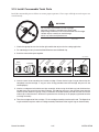
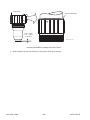
7.04 Torch Consumables Installation .................................................................... 7-3
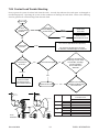
7.05 Coolant Leak Trouble-Shooting ...................................................................... 7-5

TABLE OF CONTENTS (continued)
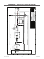
APPENDIX 1: Remote Arc Starter Schematic .......................................................................... A-1
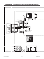
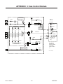
APPENDIX 2: Gas Control and Torch Valve Schematic ............................................................. A-2
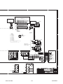
APPENDIX 3: Gas Control Module............................................................................................ A-4
APPENDIX 4: Gas Control Module PCB Layout ....................................................................... A-5
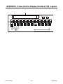
APPENDIX 5: Gas Control Display Interface PCB Layout ........................................................ A-6
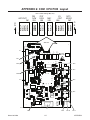
APPENDIX 6: CCM CPU PCB Layout ..................................................................................... A-7
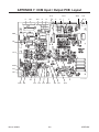
APPENDIX 7: CCM Input / Output PCB Layout ........................................................................ A-8
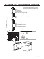
APPENDIX 8: CNC - Control Module PCB Connections ............................................................ A-9
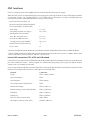
CNC functions. ................................................................................................... A-10
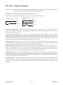
CNC Input / Output Descriptions ......................................................................... A-11
Simplified CNC Circuit. ....................................................................................... A-12
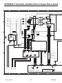
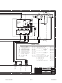
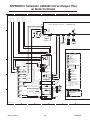
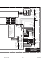
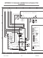
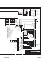
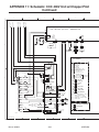
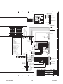
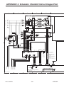
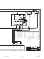
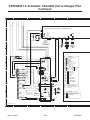
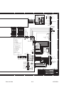
APPENDIX 9: Schematic: 230/460V Unit w/ Chopper Pilot w/ Diode ........................................ A-14
APPENDIX 9: Schematic: 230/460V Unit w/ Chopper Pilot w/ Diode Continued ....................... A-16
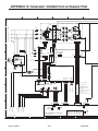
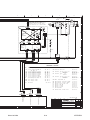
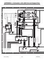
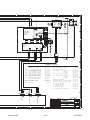
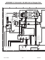
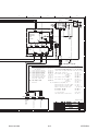
APPENDIX 10: Schematic: 230/460V Unit w/ Resistor Pilot ..................................................... A-18
APPENDIX 10: Schematic: 230/460V Unit w/ Resistor Pilot Continued .................................... A-20
APPENDIX 11: Schematic: CCC 400V Unit w/ Chopper Pilot ................................................... A-22
APPENDIX 11: Schematic: CCC 400V Unit w/ Chopper Pilot Continued .................................. A-24
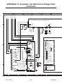
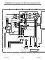
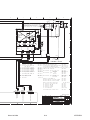
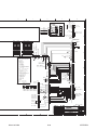
APPENDIX 12: Schematic: CE 400V Unit w/ Chopper Pilot ..................................................... A-26
APPENDIX 12: Schematic: CE 400V Unit w/ Chopper Pilot Continued ..................................... A-28
APPENDIX 13: Schematic: CE 400V Unit w/ Resistor Pilot ..................................................... A-30
APPENDIX 13: Schematic: CE 400V Unit w/ Resistor Pilot Continued ..................................... A-32
APPENDIX 14: Schematic: CSA 600V Unit w/ Chopper Pilot ................................................... A-34
APPENDIX 14: Schematic: CSA 600V Unit w/ Chopper Pilot Continued .................................. A-36
APPENDIX 15: PUBLICATION HISTORY ................................................................................ A-38
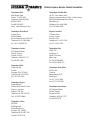
Global Customer Service Contact Information ............................... Inside Rear Cover
NOTE
Section 8, Torch operation, is provided separately.


Manual 0-5056 1-1 GENERAL INFORMATION
SECTION 1:
GENERAL INFORMATION
1.01 Notes, Cautions and Warnings
Throughout this manual, notes, cautions, and warnings are used to highlight important information. These highlights
are categorized as follows:
NOTE
An operation, procedure, or background information which requires additional emphasis or is helpful in
efficient operation of the system.
CAUTION
A procedure which, if not properly followed, may cause damage to the equipment.
WARNING
A procedure which, if not properly followed, may cause injury to the operator or others in the operating area.
1.02 Important Safety Precautions
WARNINGS
OPERATION AND MAINTENANCE OF PLASMA ARC EQUIPMENT CAN BE DANGEROUS AND HAZ-
ARDOUS TO YOUR HEALTH.
Plasma arc cutting produces intense electric and magnetic emissions that may interfere with the proper
function of cardiac pacemakers, hearing aids, or other electronic health equipment. Persons who work near
plasma arc cutting applications should consult their medical health professional and the manufacturer of
the health equipment to determine whether a hazard exists.
To prevent possible injury, read, understand and follow all warnings, safety precautions and instructions
before using the equipment. Call 1-603-298-5711 or your local distributor if you have any questions.
GASES AND FUMES
Gases and fumes produced during the plasma cutting process can be dangerous and hazardous to your health.
• Keep all fumes and gases from the breathing area. Keep your head out of the welding fume plume.
• Use an air-supplied respirator if ventilation is not adequate to remove all fumes and gases.
• The kinds of fumes and gases from the plasma arc depend on the kind of metal being used, coatings on the metal,
and the different processes. You must be very careful when cutting or welding any metals which may contain one
or more of the following:
Antimony Chromium Mercury Beryllium
Arsenic Cobalt Nickel Lead
Barium Copper Selenium Silver
Cadmium Manganese Vanadium

GENERAL INFORMATION 1-2 Manual 0-5056
• Always read the Material Safety Data Sheets (MSDS) that should be supplied with the material you are using.
These MSDSs will give you the information regarding the kind and amount of fumes and gases that may be
dangerous to your health.
• For information on how to test for fumes and gases in your workplace, refer to item 1 in Subsection 1.03,
Publications in this manual.
• Use special equipment, such as water or down draft cutting tables, to capture fumes and gases.
• Do not use the plasma torch in an area where combustible or explosive gases or materials are located.
• Phosgene, a toxic gas, is generated from the vapors of chlorinated solvents and cleansers. Remove all sources
of these vapors.
• This product, when used for welding or cutting, produces fumes or gases which contain chemicals known to the
State of California to cause birth defects and, in some cases, cancer. (California Health & Safety Code Sec.
25249.5 et seq.)
ELECTRIC SHOCK
Electric Shock can injure or kill. The plasma arc process uses and produces high voltage electrical energy. This
electric energy can cause severe or fatal shock to the operator or others in the workplace.
• Never touch any parts that are electrically “live” or “hot.”
• Wear dry gloves and clothing. Insulate yourself from the work piece or other parts of the welding circuit.
• Repair or replace all worn or damaged parts.
• Extra care must be taken when the workplace is moist or damp.
• Install and maintain equipment according to NEC code, refer to item 9 in Subsection 1.03, Publications.
• Disconnect power source before performing any service or repairs.
• Read and follow all the instructions in the Operating Manual.
FIRE AND EXPLOSION
Fire and explosion can be caused by hot slag, sparks, or the plasma arc.
• Be sure there is no combustible or flammable material in the workplace. Any material that cannot be removed
must be protected.
• Ventilate all flammable or explosive vapors from the workplace.
• Do not cut or weld on containers that may have held combustibles.
• Provide a fire watch when working in an area where fire hazards may exist.
• Hydrogen gas may be formed and trapped under metal work pieces when they are cut underwater or while
using a water table. DO NOT cut underwater or on a water table unless the hydrogen gas can be eliminated or
dissipated. Trapped hydrogen gas that is ignited will cause an explosion.
• Aluminum fumes (made of ultra fine aluminum solid particles) maybe formed and trapped under aluminum
work pieces when they are cut underwater or while using a water table. DO NOT cut aluminum alloys underwa-
ter or on a water table unless the aluminum fumes can be eliminated or dissipated. Trapped aluminum fume that
readily and violently reacts with water will cause an explosion.

Manual 0-5056 1-3 GENERAL INFORMATION
NOISE
Noise can cause permanent hearing loss. Plasma arc processes can cause noise levels to exceed safe limits. You
must protect your ears from loud noise to prevent permanent loss of hearing.
• To protect your hearing from loud noise, wear protective ear plugs and/or ear muffs. Protect others in the work-
place.
• Noise levels should be measured to be sure the decibels (sound) do not exceed safe levels.
• For information on how to test for noise, see item 1 in Subsection 1.03, Publications, in this manual.
PLASMA ARC RAYS
Plasma Arc Rays can injure your eyes and burn your skin. The plasma arc process produces very bright ultra violet and
infra red light. These arc rays will damage your eyes and burn your skin if you are not properly protected.
• To protect your eyes, always wear a welding helmet or shield. Also always wear safety glasses with side shields,
goggles or other protective eye wear.
• Wear welding gloves and suitable clothing to protect your skin from the arc rays and sparks.
• Keep helmet and safety glasses in good condition. Replace lenses when cracked, chipped or dirty.
• Protect others in the work area from the arc rays. Use protective booths, screens or shields.
• Use the shade of lens as suggested in the following per ANSI/ASC Z49.1:
Minimum Protective Suggested
Arc Current Shade No. Shade No.
Less Than 300* 8 9
300 - 400* 9 12
400 - 800* 10 14
* These values apply where the actual arc is clearly seen. Experience has shown that lighter filters may be
used when the arc is hidden by the workpiece.
1.03 Publications
Refer to the following standards or their latest revisions for more information:
1. OSHA, SAFETY AND HEALTH STANDARDS, 29CFR 1910, obtainable from the Superintendent of Documents,
U.S. Government Printing Office, Washington, D.C. 20402
2. ANSI Standard Z49.1, SAFETY IN WELDING AND CUTTING, obtainable from the American Welding Society, 550
N.W. LeJeune Rd, Miami, FL 33126
3. NIOSH, SAFETY AND HEALTH IN ARC WELDING AND GAS WELDING AND CUTTING, obtainable from the Super-
intendent of Documents, U.S. Government Printing Office, Washington, D.C. 20402
4. ANSI Standard Z87.1, SAFE PRACTICES FOR OCCUPATION AND EDUCATIONAL EYE AND FACE PROTEC-
TION, obtainable from American National Standards Institute, 1430 Broadway, New York, NY 10018
5. ANSI Standard Z41.1, STANDARD FOR MEN’S SAFETY-TOE FOOTWEAR, obtainable from the American National
Standards Institute, 1430 Broadway, New York, NY 10018
6. ANSI Standard Z49.2, FIRE PREVENTION IN THE USE OF CUTTING AND WELDING PROCESSES, obtainable
from American National Standards Institute, 1430 Broadway, New York, NY 10018
7. AWS Standard A6.0, WELDING AND CUTTING CONTAINERS WHICH HAVE HELD COMBUSTIBLES, obtainable
from American Welding Society, 550 N.W. LeJeune Rd, Miami, FL 33126

GENERAL INFORMATION 1-4 Manual 0-5056
8. NFPA Standard 51, OXYGEN-FUEL GAS SYSTEMS FOR WELDING, CUTTING AND ALLIED PROCESSES, ob-
tainable from the National Fire Protection Association, Batterymarch Park, Quincy, MA 02269
9. NFPA Standard 70, NATIONAL ELECTRICAL CODE, obtainable from the National Fire Protection Association,
Batterymarch Park, Quincy, MA 02269
10.NFPA Standard 51B, CUTTING AND WELDING PROCESSES, obtainable from the National Fire Protection Asso-
ciation, Batterymarch Park, Quincy, MA 02269
11. CGA Pamphlet P-1, SAFE HANDLING OF COMPRESSED GASES IN CYLINDERS, obtainable from the Com-
pressed Gas Association, 1235 Jefferson Davis Highway, Suite 501, Arlington, VA 22202
12.CSA Standard W117.2, CODE FOR SAFETY IN WELDING AND CUTTING, obtainable from the Canadian Standards
Association, Standards Sales, 178 Rexdale Boulevard, Rexdale, Ontario, Canada M9W 1R3
13.NWSA booklet, WELDING SAFETY BIBLIOGRAPHY obtainable from the National Welding Supply Association,
1900 Arch Street, Philadelphia, PA 19103
14.American Welding Society Standard AWSF4.1, RECOMMENDED SAFE PRACTICES FOR THE PREPARATION
FOR WELDING AND CUTTING OF CONTAINERS AND PIPING THAT HAVE HELD HAZARDOUS SUBSTANCES,
obtainable from the American Welding Society, 550 N.W. LeJeune Rd, Miami, FL 33126
15.ANSI Standard Z88.2, PRACTICE FOR RESPIRATORY PROTECTION, obtainable from American National Stan-
dards Institute, 1430 Broadway, New York, NY 10018

Manual 0-5056 1-5 GENERAL INFORMATION
1.04 Declaration of Conformity
Manufacturer: Thermal Dynamics Corporation
Address: 82 Benning Street
West Lebanon, New Hampshire 03784
USA
The equipment described in this manual conforms to all applicable aspects and regulations of the ‘Low Voltage
Directive’ (European Council Directive 73/23/EEC as amended by Council Directive 93/68/EEC) and to the National
legislation for the enforcement of this Directive.
The equipment described in this manual conforms to all applicable aspects and regulations of the "EMC Directive"
(European Council Directive 89/336/EEC) and to the National legislation for the enforcement of this Directive.
Serial numbers are unique with each individual piece of equipment and details description, parts used to manufacture
a unit and date of manufacture.
National Standard and Technical Specifications
The product is designed and manufactured to a number of standards and technical requirements. Among them are:
* CSA (Canadian Standards Association) standard C22.2 number 60 for Arc welding equipment.
* UL (Underwriters Laboratory) rating 94VO flammability testing for all printed-circuit boards used.
* ISO/IEC 60974-1 (BS 638-PT10) (EN 60 974-1) (EN50192) (EN50078) applicable to plasma cutting equipment and
associated accessories.
* CENELEC EN50199 EMC Product Standard for Arc Welding Equipment
* For environments with increased hazard of electrical shock, Power Supplies bearing the
S
mark conform to
EN50192 when used in conjunction with hand torches with exposed tips, if equipped with properly installed stand-
off guides.
* Extensive product design verification is conducted at the manufacturing facility as part of the routine design and
manufacturing process. This is to ensure the product is safe, when used according to instructions in this manual and
related industry standards, and performs as specified. Rigorous testing is incorporated into the manufacturing
process to ensure the manufactured product meets or exceeds all design specifications.
Thermal Dynamics has been manufacturing products for more than 30 years, and will continue to achieve excellence
in our area of manufacture.
Manufacturers responsible representative: Steve Ward
Operations Director
Thermadyne Europe
Europa Building
Chorley N Industrial Park
Chorley, Lancashire,
England PR6 7BX

GENERAL INFORMATION 1-6 Manual 0-5056
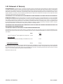
1.05 Statement of Warranty
LIMITED WARRANTY: Thermal Dynamics
®
Corporation (hereinafter “Thermal”) warrants that its products will be free of defects in workmanship
or material. Should any failure to conform to this warranty appear within the time period applicable to the Thermal products as stated below,
Thermal shall, upon notification thereof and substantiation that the product has been stored, installed, operated, and maintained in accordance
with Thermal’s specifications, instructions, recommendations and recognized standard industry practice, and not subject to misuse, repair,
neglect, alteration, or accident, correct such defects by suitable repair or replacement, at Thermal’s sole option, of any components or parts
of the product determined by Thermal to be defective.
THIS WARRANTY IS EXCLUSIVE AND IS IN LIEU OF ANY WARRANTY OF MERCHANTABILITY OR FITNESS FOR A PARTICULAR PURPOSE.
LIMITATION OF LIABILITY: Thermal shall not under any circumstances be liable for special or consequential damages, such as, but not limited
to, damage or loss of purchased or replacement goods, or claims of customers of distributor (hereinafter “Purchaser”) for service interruption.
The remedies of the Purchaser set forth herein are exclusive and the liability of Thermal with respect to any contract, or anything done in
connection therewith such as the performance or breach thereof, or from the manufacture, sale, delivery, resale, or use of any goods covered
by or furnished by Thermal whether arising out of contract, negligence, strict tort, or under any warranty, or otherwise, shall not, except as
expressly provided herein, exceed the price of the goods upon which such liability is based.
THIS WARRANTY BECOMES INVALID IF REPLACEMENT PARTS OR ACCESSORIES ARE USED WHICH MAY IMPAIR THE SAFETY OR
PERFORMANCE OF ANY THERMAL PRODUCT.
THIS WARRANTY IS INVALID IF THE PRODUCT IS SOLD BY NON-AUTHORIZED PERSONS.
The limited warranty periods for this product shall be: A maximum of three (3) years from date of sale to an authorized distributor and a
maximum of two (2) years from date of sale by such distributor to the Purchaser, and with further limitations on such two (2) year period (see
chart below).
Parts
Labor
AutoCut
©
and UltraCut
©
Power Supplies and Components 2 Years 1 Year
Torch And Leads
XT
TM
-30O2 / XT
TM
-301 Torch (Excluding Consumable Parts) 1 Year 1 Year
Repair/Replacement Parts 90 Days 90 Days
Warranty repairs or replacement claims under this limited warranty must be submitted by an authorized Thermal Dynamics® repair facility within
thirty (30) days of the repair. No transportation costs of any kind will be paid under this warranty. Transportation charges to send products
to an authorized warranty repair facility shall be the responsibility of the customer. All returned goods shall be at the customer’s risk and
expense. This warranty supersedes all previous Thermal warranties.
Effective December 10, 2007

Manual No. 0-5056 2-1 SPECIFICATIONS
SECTION 2: SPECIFICATIONS
2.01 General Description Of The System
A typical Ultra-Cut
®
200 system configuration includes:
• One Power Supply
• Remote Arc Starter
• Gas Control Module
• Torch Valve Assembly
• Precision Plasma Cutting Torch
• Set Of Connecting Leads
• Torch Spare Parts Kit
The components are connected at installation.
2.02 Plasma Power Supply
The power supply provides the necessary current for cutting operations. The power supply also monitors system
performance, and cools and circulates the liquid coolant for the torch and leads.
2.03 Remote Arc Starter
This unit produces a temporary HF pulse to start the pilot arc. The pilot arc creates a path for the main arc to
transfer to the work. When the main arc is established, the pilot arc shuts off.
2.04 Gas Control Module
This module allows remote setting of gas selection, pressures, and flows together with setting of cutting current.
2.05 Precision Plasma Cutting Torch
The torch delivers the controlled current to the work through the main arc, causing the metal to be cut.

Manual No. 0-5056 2-2 SPECIFICATIONS
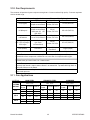
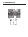
2.06 Specifications & Electrical Requirements
Maximum OCV (U
0
) 380 vdc
Maximum Output Current 200 Amps
Maximum Output Voltage 230 vdc
Duty Cycle Rating
100% @ 200A, 180vdc (32 kW),
@ 104F° (40°C) Ambient Temperature
Operating range 14°F to 122°F (-10°C to + 50°C)
Power Factor 0.70 @ 100 ADC Output
Cooling Forced Air (Class F)
Ultra-Cut® 200 Power Supply Specifications
Input Power Input Current
Voltage Freq. 3-Ph 3-Ph Fuse (Amps) Wire (AWG)
(Volts) (Hz) (kVA) (Amps) 3-Ph 3-Ph
208 60 47 130 160
#2
2
230 60 49 125 150
#2
2
400505477100
#2
1
400 (CE) 50 54 77 100
#2
1
46060597590
#2
1
Ultra-Cut 200 Power Supply Electrical Input
s
2
Extra Hard Usage Type G, G-GC, W
Suggested Sizes (See Note)
Line Voltages with Suggested Circuit Protection and Wire Sizes
1
Extra Hard Usage Type SO, SOW, SOO, SOOW, ST, STW, STO, STOW, STOO, STOOW
Based on National Electric Code and Canadian Electrical Code
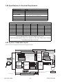
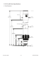
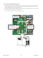
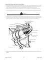
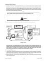
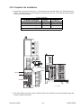
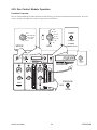
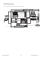
2.07 System Component Layout
Refer to section 3.11 for ground connections and ground cables.
Primary power
Work
CNC
Remote
Arc
Starter
Art # A-07233_AB
Torch
Coolant Supply
Coolant Return
Control Cable
Pilot Return
Coolant Supply
Coolant Return
Plasma Gas
Shield Gas
Work Cable
Fiber
Optic
Cable
Control
Cable
Gas Control
Module
Power
Supply
Torch
Valve
Assembly
Positioning Tube
Plasma Gas
Preflow Gas
Water Shield
Shield
Shield Gas
Negative
Pilot Return
Control Cable
100’ / 30.5 m Maximum Length
125’ / 38.1 m Maximum Length
175’ / 53.3 m Maximum Length
Shield
H
Q
R
T
S
A
B
C
D
E
P
K
L
O
I
J
G
175’ / 53.3 m Maximum Length

Manual No. 0-5056 2-3 SPECIFICATIONS
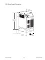
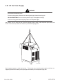
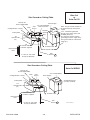
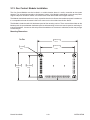
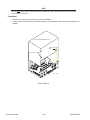
2.08 Power Supply Dimensions
Art # A-07182
37.75 inch
960 mm
27.5 inch
700 mm
33 inch
840 mm
27 inch
680 mm
41.25 inch
1050 mm
433 lb / 196 kg

Manual No. 0-5056 2-4 SPECIFICATIONS
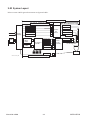
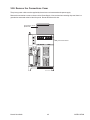
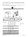
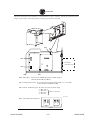
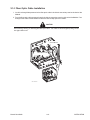
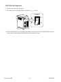
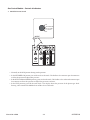
2.09 Power Supply Rear Panel Features
Terminal Cover
Support Panel
Coolant Tank
Coolant Filter
Coolant Connections
Input Power
Terminals
Pilot (Pos) Terminal
Circuit Breaker
Panel
Terminal Cover
AC Power Lamp
Ground Terminals
Gas Control
Console Connector
RETURN
SUPPLY
Art # A-04794
CNC Connector
Remote Arc Starter
Connector
Work Cable Terminal
Torch (Neg) Terminal
Leads
Bracket

Manual No. 0-5056 2-5 SPECIFICATIONS
2.10 Gas Requirements
The customer will provide all gases and pressure regulators. Gases must be of high quality. Pressure regulators
shall be double stage.
Gas Quality Minimum Pressure Flow
O2 (Oxygen)
99.5% Purity
(Liquid recommended)
120 psi
8.3 bar / 827 kPa
75 scfh (2123 l/h)
N2 (Nitrogen)
99.5% Purity
(Liquid recommended)
<1000 ppm O2, <32
ppm H2O)
120 psi
8.3 bar / 827 kPa
180 scfh (5097 l/h)
Compressed
or Bottled Air
Clean, Dry,
Free of Oil (see Note 1)
120 psi
8.3 bar / 827 kPa
185 schf (5238 l/h)
H35 (Argon-Hydrogen)
H35 = 35% Hydrogen,
65% Argon
99.995% Purity
(gas liquid
recommended)
120 psi
8.3 bar / 827 kPa
85 scfh (2406 l/h)
H2O (Water) See Note 2
50 psi (3.5 bar)
See Note 3
10 gph (38 lph)
Ultra-Cut 200 Power Supply: Gas Pressures, Flows, and Quality Requirements
Note 2
: The tap water source does not need to be deionized, but in water systems with
extremely high mineral content a water softener is recommended. Tap water with high levels of
particulate matter must be filtered.
Note 1:
The air source must be adequately filtered to remove all oil or grease. Oil or grease
contamination from compressed or bottled air can cause fires in conjunction with oxygen.
Note 3:
Water Pressure Regulator No. 8-6118 is recommended to ensure
proper water pressure.
For filtering, a coalescing filter able to filter to 0.01 microns should be installed as close as
possible to the gas inlets on the Gas Control Module.
Maximum Input Pressure 135 psi (9.3 bar)
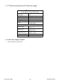
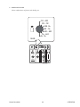
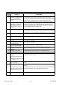
2.11 Gas Applications
MATERIAL
PRE-
FLOW
PLASMA SHIELD
PRE-
FLOW
PLASMA SHIELD
PRE-
FLOW
PLASMA SHIELD
Air Air Air
Air O
2 Air
Air Air Air Air Air Air Air Air Air
N2 N
2 H20N2 N2 H20
N2 H
35
N
2
N2 H
35
N
2
Air Air Air
Air O
2
Air
GAS TYPEGAS TYPE
Air Air Air Air
55 A
100 A
MILD STEEL STAINLESS STEEL ALUMINUM
200 A
GAS TYPE
Air
CUTTING
OUTPUT
O
2
Air
Air Air

Manual No. 0-5056 2-6 SPECIFICATIONS
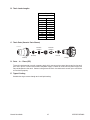
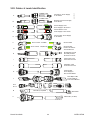
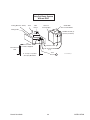
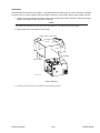
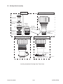
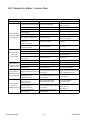
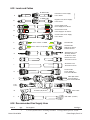
2.12 XT
TM
-300 Torch Specifications
A. Torch Dimensions
2.25"
57.15 mm
2.0"
50.8 mm
2.39"
60.81 mm
1.49"
37.8 mm
19.00"
482.68 mm
15.50"
393.78 mm
2.63"
66.8 mm
1.57"
39.96 mm
3.98"
101.1 mm
6.30"
160.10 mm
Art # A-08301
Mounting Tube
End Cap
Page is loading ...
Page is loading ...
Page is loading ...
Page is loading ...
Page is loading ...
Page is loading ...
Page is loading ...
Page is loading ...
Page is loading ...
Page is loading ...
Page is loading ...
Page is loading ...
Page is loading ...
Page is loading ...
Page is loading ...
Page is loading ...
Page is loading ...
Page is loading ...
Page is loading ...
Page is loading ...
Page is loading ...
Page is loading ...
Page is loading ...
Page is loading ...
Page is loading ...
Page is loading ...
Page is loading ...
Page is loading ...
Page is loading ...
Page is loading ...
Page is loading ...
Page is loading ...
Page is loading ...
Page is loading ...
Page is loading ...
Page is loading ...
Page is loading ...
Page is loading ...
Page is loading ...
Page is loading ...
Page is loading ...
Page is loading ...
Page is loading ...
Page is loading ...
Page is loading ...
Page is loading ...
Page is loading ...
Page is loading ...
Page is loading ...
Page is loading ...
Page is loading ...
Page is loading ...
Page is loading ...
Page is loading ...
Page is loading ...
Page is loading ...
Page is loading ...
Page is loading ...
Page is loading ...
Page is loading ...
Page is loading ...
Page is loading ...
Page is loading ...
Page is loading ...
Page is loading ...
Page is loading ...
Page is loading ...
Page is loading ...
Page is loading ...
Page is loading ...
Page is loading ...
Page is loading ...
Page is loading ...
Page is loading ...
Page is loading ...
Page is loading ...
Page is loading ...
Page is loading ...
Page is loading ...
Page is loading ...
Page is loading ...
Page is loading ...
Page is loading ...
Page is loading ...
Page is loading ...
Page is loading ...
Page is loading ...
Page is loading ...
Page is loading ...
Page is loading ...
Page is loading ...
Page is loading ...
Page is loading ...
Page is loading ...
Page is loading ...
Page is loading ...
Page is loading ...
Page is loading ...
Page is loading ...
Page is loading ...
Page is loading ...
Page is loading ...
Page is loading ...
Page is loading ...
Page is loading ...
Page is loading ...
Page is loading ...
Page is loading ...
Page is loading ...
Page is loading ...
Page is loading ...
Page is loading ...
Page is loading ...
Page is loading ...
Page is loading ...
Page is loading ...
Page is loading ...
Page is loading ...
Page is loading ...
Page is loading ...
Page is loading ...
Page is loading ...
Page is loading ...
Page is loading ...
Page is loading ...
Page is loading ...
Page is loading ...
Page is loading ...
Page is loading ...
Page is loading ...
Page is loading ...
Page is loading ...
Page is loading ...
Page is loading ...
Page is loading ...
Page is loading ...
-
 1
1
-
 2
2
-
 3
3
-
 4
4
-
 5
5
-
 6
6
-
 7
7
-
 8
8
-
 9
9
-
 10
10
-
 11
11
-
 12
12
-
 13
13
-
 14
14
-
 15
15
-
 16
16
-
 17
17
-
 18
18
-
 19
19
-
 20
20
-
 21
21
-
 22
22
-
 23
23
-
 24
24
-
 25
25
-
 26
26
-
 27
27
-
 28
28
-
 29
29
-
 30
30
-
 31
31
-
 32
32
-
 33
33
-
 34
34
-
 35
35
-
 36
36
-
 37
37
-
 38
38
-
 39
39
-
 40
40
-
 41
41
-
 42
42
-
 43
43
-
 44
44
-
 45
45
-
 46
46
-
 47
47
-
 48
48
-
 49
49
-
 50
50
-
 51
51
-
 52
52
-
 53
53
-
 54
54
-
 55
55
-
 56
56
-
 57
57
-
 58
58
-
 59
59
-
 60
60
-
 61
61
-
 62
62
-
 63
63
-
 64
64
-
 65
65
-
 66
66
-
 67
67
-
 68
68
-
 69
69
-
 70
70
-
 71
71
-
 72
72
-
 73
73
-
 74
74
-
 75
75
-
 76
76
-
 77
77
-
 78
78
-
 79
79
-
 80
80
-
 81
81
-
 82
82
-
 83
83
-
 84
84
-
 85
85
-
 86
86
-
 87
87
-
 88
88
-
 89
89
-
 90
90
-
 91
91
-
 92
92
-
 93
93
-
 94
94
-
 95
95
-
 96
96
-
 97
97
-
 98
98
-
 99
99
-
 100
100
-
 101
101
-
 102
102
-
 103
103
-
 104
104
-
 105
105
-
 106
106
-
 107
107
-
 108
108
-
 109
109
-
 110
110
-
 111
111
-
 112
112
-
 113
113
-
 114
114
-
 115
115
-
 116
116
-
 117
117
-
 118
118
-
 119
119
-
 120
120
-
 121
121
-
 122
122
-
 123
123
-
 124
124
-
 125
125
-
 126
126
-
 127
127
-
 128
128
-
 129
129
-
 130
130
-
 131
131
-
 132
132
-
 133
133
-
 134
134
-
 135
135
-
 136
136
-
 137
137
-
 138
138
-
 139
139
-
 140
140
-
 141
141
-
 142
142
-
 143
143
-
 144
144
-
 145
145
-
 146
146
-
 147
147
-
 148
148
-
 149
149
-
 150
150
-
 151
151
-
 152
152
-
 153
153
-
 154
154
-
 155
155
-
 156
156


ESAB 200 ULTRA-CUT™ Plasma Cutting System User manual
- Category
- Welding System
- Type
- User manual
Ask a question and I''ll find the answer in the document
Finding information in a document is now easier with AI
Related papers
-
ESAB 200 AUTO-CUT® Plasma Cutting System User manual
-
-
-
-
-
ESAB Plasma Cutting System Model Drag-Gun Plus with Built-In Air Compressor User manual
-
-
-
-
Other documents
-
 RUN BISON HT-G2LHB-2FT3L-F8155/277-250D 4PK Installation guide
-
Intermatic IG2T3R Supplementary Manual
-
Electro-Voice Converting P3000 230VAC to 120VAC Owner's manual
-
 Thermal Dynamics 101 CUTMASTER Operating instructions
-
 Thermal Comfort 3000 User manual
-
Victor Cutmaster 52 Operating instructions
-
 Thermal Dynamics CE CutMaster 50 User manual
-
 Thermal Dynamics 38 Cutmaster Operating instructions
-
Horstmann HCT2 User guide
-
 Thermal Dynamics CUTSKILL C-100A Operating instructions


