Page is loading ...

Raven Series Modular Media
Converter System
MIL-RCM16A and MIL-RCM16D 16 Slot Raven
Conversion Modules Managed Chassis with
AC or DC Power Source
USER GUIDE

Regulatory Approval
- FCC Class A
- UL 1950
- CSA C22.2 No. 950
- EN60950
- CE
- EN55022 Class A
- EN55024
Canadian EMI Notice
This Class A digital apparatus meets all the requirements of the Canadian Interference-Causing Equipment Regulations.
Cet appareil numerique de la classe A respecte toutes les exigences du Reglement sur le materiel brouilleur du Canada.
European Notice
Products with the CE Marking comply with both the EMC Directive (89/336/EEC) and the Low Voltage Directive (73/23/EEC)
issued by the Commission of the European Community Compliance with these directives imply conformity to the following
European Norms:
- EN55022 (CISPR 22) - Radio Frequency Interference
- EN61000-X - Electromagnetic Immunity
- EN60950 (IEC950) - Product Safety
Five-Year Limited Warranty
MiLAN Technology warrants to the original consumer or purchaser that each of it's products, and
all components thereof, will be free from defects in material and/or workmanship for a
period of five years from the original factory shipment date. Any warranty hereunder is
extended to the original consumer or purchaser and is not assignable.
MiLAN Technology makes no express or implied warranties including, but not limited to, any
implied warranty of merchantability or fitness for a particular purpose, except as expressly set
forth in this warranty. In no event shall MiLAN Technology be liable for incidental or
consequential damages, costs, or expenses arising out of or in connection with the
performance of the product delivered hereunder. MiLAN Technology will in no case cover damages
arising out of the product being used in a negligent fashion or manner.
Trademarks
The MiLAN logo and MiLAN Technology trademarks are registered trademarks of MiLAN Technology in the
United States and/or other countries.
To Contact MiLAN Technology
For prompt response when calling for service information, have the following information ready:
- Product serial number and revision
- Date of purchase
- Vendor or place of purchase
You can reach MiLAN Technology technical support at:
E-mail: [email protected]
Telephone: +1.408.744.2751
Fax: +1.408.744.2771
MiLAN Technology
1329 Moffett Park Drive
Sunnyvale, CA 94089
United States of America
Telephone: +1.408.744.2775
Fax: +1.408.744.2793
http://www.milan.com
© Copyright 2003 MiLAN Technology P/N: 90000414 Rev. A2

Table of Contents
1. Introduction
Features
Intelligent Features
Management Methods
Console and Telnet Management
Web-based Management
SNMP Network Management
Package Contents
2. Hardware Description
Front Panel
Rear Panel
LED Indicators
RS-232 Console
3. Connecting to the Network
Pre-Installation Requirements
Mounting the Device
Desktop Installation
Rack-mounted Installation
Power On
Diagnostic Test
4. Network Configuration
Connecting a Terminal or PC to the Console Port
4-1. Main Menu
4-1-1. Device Settings
4-1-2. Modules Settings
4-1-3. Redundant Power Status
4-1-4. Events Log
4-1-5. SNMP Trap
4-1-6. Secure IP for Telnet, HTTP, and SNMP
4-1-7. Save Current Settings
4-1-8. Factory Default Settings & Reboot System
4-1-9. Reboot System

5. Web-Based Management
5-1. System Login
5-2. System Configuration
5-2-1. Home Page
5-2-2. Modules Settings
5-2-3. IP Configuration
5-2-4. SNMP
5-2-5. Save and Reboot
5-2-5-1. Save Settings
5-2-5-2. Reboot System
5-2-6. Upgrade Firmware
6. SNMP Management
6-1. SNMP Management
7. Technical Specifications
Appendix A. Internet Explorer Setting

1
1.
Introduction
The Raven Series Modular Media Converter System is a combination of
16-slot host cabinet and various optional media converter modules. A
maximum of sixteen modules can be installed in the cabinet. The power
supply will support AC or DC, with an optional matching power supply for
load sharing and redundancy.
Figure 1-1. The Raven Series Media Converter System
With built-in web-based Management, managing and configuring the
conversion system is simplified. The web browser may be used to
configure and manage the network, from cabinet level management to port
level control and monitoring. Use of a mouse replaces typing of command
strings. The switch can also be managed via Telnet, Console, or SNMP
Management.

2
Features
Cabinet conforms to IEEE 802.3 and IEEE802.3u
Sixteen Converter Module slots
One built-in module with a RS-232 console port and a Fast
Ethernet RJ-45 port for In-band management
Half-duplex mode for backpressure, and full-duplex for
flow-control in management Ethernet port.
System LED indicators: Power Good (A, B), Power Fail (A,
B), System power, CPU Ready, Ethernet port link/activity,
Full duplex
Hot swappable bracket module design
Converter module options:
10/100TX to 100FX single mode with SC connector (30 KM),
10/100TX to 100FX multi-mode with ST/SC/MT-RJ connector
(2 KM), 10/100TX to VDSL
Intelligent Features
Web-based management
SNMP network management
Console and Telnet management
Module-specific configuration by Web Browser, Telnet or
Console
Automatic module type display

3
Management Methods
The Raven Series Modular Media Converter System supports the following
management methods:
Console and Telnet Management
Web-based Management
SNMP Network Management
Console and Telnet Management
Console Management is done through the RS-232 Console Port.
Managing the conversion system in this method requires a direct
connection between a PC and the built-in management module. Telnet
management requires a network connection. The default IP address is
192.168.1.77 with a subnet mask of 255.255.255.0. This default address
can be used to login and change the configuration using Telnet.
Web-based Management
The conversion system provides an embedded HTML web server residing
in flash memory. It offers advanced management features and allows
users to manage the conversion system from anywhere on the network
through a standard browser such as Microsoft Internet Explorer or
Netscape.
SNMP Network Management
SNMP (Simple Network Management Protocol) provides a means to
monitor and control network devices, and to manage configurations,
statistic collection, performance, and security.
Data is passed from SNMP agents, which are hardware & software
processes reporting activity in each network device, to the workstation
console used to oversee the network. The SNMP agents return information
contained in a MIB (Management Information Base), which is a data
structure that defines what is obtainable from the device and what can be
controlled.

4
Package Contents
Unpack the contents of the package and verify them against the checklist
below.
Raven Series Chassis (Conversion Modules ship separately)
Power Cord
Four Rubber Feet
RS-232 cable
CD ROM containing Users Guide
Warranty Card
If any item is missing or damaged, please contact your local dealer for
service.

5
2.
Hardware Description
Front Panel
Figure 2.1 below shows the Raven Series Media Converter Chassis fully
populated with sixteen Raven Series Media Converter Modules and one
RS232/Fast Ethernet RJ-45 Management Module.
Figure 2-1. Front Panel for Raven Series Modular Media Converter System
Figure 2-2. Front Panel for Raven
Series Multi-mode ST Module
Figure 2-4. Front Panel for Raven
Series Multi-mode SC module
Figure 2-3. Front Panel for Raven
Series Single Mode SC module
Figure 2-5. Front Panel for Raven
Series Multi-mode VF-45 module

6
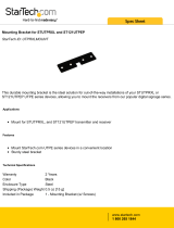
Rear Panel
The 3-pronged power plug and power on/off switch are located at the Rear
Panel of the Raven Series chassis, as shown in Figure 2-6. The equipment
will work with AC in the range 100-240VAC, 50-60Hz (AC type power
supply) or DC power in the range 40.5 ~57.0 @ 20A (DC type power
supply).
The conversion system ships standard with one power module and one fan
module. An additional power module unit is optional for load sharing and
redundancy.
Note: Redundant power modules must be the same type power supply.
AC power and DC power are not available in a single system.
F
igure 2-6.
R
ear Pane
l
Power Slot A ships with
either an AC or DC power
module.
Power Slot B ships with a fan
module standard or an optional
redundant power module.

7
LED Indicators
All LED status indicators are located on the front panel of the conversion
system. There are eight LED-indicators on the CPU Module and six
LED-indicators on each of the Fast Ethernet to Fiber converter modules.
The following tables provide descriptions of the LED statuses and meaning.
They provide a real-time indication of systematic operation status.
Fast Ethernet to Fiber Conversion Modules
LED Status Meaning
Speed (RJ-45)
On (Green) Link is on 100Mbps mode
On Ethernet link up
LINK/ACT
(RJ-45)
Flashing (Green) Port is transmitting packets
On Link is on Full Duplex mode
FDX (RJ-45)
Off Link is on Half Duplex mode
Power
On (Green) Power on
On Ethernet Link up
LINK/ACT
(Fiber)
Flashing (Green) Port is transmitting packets
On Link is on Full Duplex mode
FDX (Fiber)
Off Link is on Half Duplex mode
LK/ACT
On / Flashing
Ethernet power link is up / packet
is transmittin
g
FDX
On / Flashing
Ethernet link is on Full Duplex
mode / Collision
Table 2-1. Fast Ethernet to Fiber Converter Module LED-indicator statuses and
meaning

8
Management Module
Figure 2-7.Management Module LED-indicators
LED Status Meaning
CPU Ready
Flashing (Green) System kernel is working correctly
PWR
On System power is ready
On Power Module A is ready
Good A
Off Power Module A is not ready
On Power Module B is ready
Good B
Off Power Module B is not ready
On Power Module A is fail
Fail A
Off Power Module A is ready
On Power Module B is fail
Fail B
Off Power Module B is ready
LK/ACT
On / Flashing
Ethernet power is link up / packet is
transmittin
g
FDX
On / Flashing
Ethernet is link on Full Duplex
mode / Collision
Table 2-2. CPU Module LED-indicator statuses and meaning

9
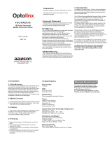
RS-232 Console
The console port is used to connect a management station or terminal with
the conversion system. Use the RS-232 serial port for out-of-band
management.
Figure 2-8.Management Module Serial Port Pinouts

10
3.
Connecting to the Network
Pre-Installation Requirements
You will need the following prior to installing the hardware:
• PC or Workstation with 10/100BASE-TX Ethernet card or RS-232
serial port: Your PC must have a standard Ethernet interface or Serial
port to connect to the Device.
• Ethernet UTP cable with RJ-45 connector or DB-9 RS-232 Serial
cable: Check if the cable and connectors work properly.
• A power outlet: 100 to 240V AC at 50 to 60 Hz or DC power.
Make sure that the Device power is accessible and power cords can be
connected easily.
• Dedicated power supply: Use dedicated power circuits or power
conditioners to supply reliable electrical power to the network devices.
• A dry cool place: Keep the Device away from moisture. Avoid direct
sunlight, heat source, and high amounts of electromagnetic
interference, all of which will adversely affect the performance of the
Device.
• Mounting tools: If you intend to mount the device on a rack, make sure
you have all the tools, mounting brackets, screws.
Mounting the Device
The Raven Series Modular Media Converter System is suitable for use in
an office environment where it can be rack-mounted in standard EIA
19-inch racks or used in a standalone configuration.

11
Desktop Installation
Set the conversion system on a sufficiently large flat space with a power
outlet nearby. The surface where you put your conversion system should
be clean, smooth, level, and sturdy. Provide enough clearance around the
conversion system to allow attachment of cables, power cord and air
circulation.
Attaching Rubber Feet
A. Make sure mounting surface on the bottom of the conversion system is
grease and dust free.
B. Remove adhesive backing from the rubber feet.
C. Apply the rubber feet to each corner on the bottom of the conversion
system. These footpads can prevent the conversion system from
shock/vibration.
Figure 3-1. Attaching rubber feet to each corner on the bottom of the conversion
system

12
Rack-mounted Installation
The Raven Series Media Converter System includes a rack-mount kit that
allows it to be mounted in an EIA standard size, 19-inch rack.
Perform the following steps to rack mount the conversion system:
A. Position one bracket to align with the holes on one side of the
conversion system and secure it with the bracket screws. Then attach
the remaining bracket to the other side of the conversion system.
Figure 3-2. Attach mounting brackets with screws

13
B. After attaching both mounting brackets, position the conversion
system in the rack by lining up the holes in the brackets with the
appropriate holes on the rack. Secure the conversion system to the
rack with a screwdriver and the rack-mounting screws.
Figure 3-3. Mounting the Raven Series Media Converter System in an EIA
standard 19-inch Rack
Note: For proper ventilation, allow at least 4 inches (10 cm) of clearance
on the front and 3.4 inches (8 cm) on the back of the conversion system.
This is especially important for enclosed rack installations.

14
Power On
Connect the power cord to the power socket on the rear panel of the
conversion system. Connect the other end of the cord to an appropriate
power outlet.
Press the power On/Off switch to the On position and check the power
indicator on the front panel to see if power is properly supplied.
Diagnostic Test
The system will automatically perform a diagnostic test once the
installation is completed and power is applied to the device.
When the Power LED is on for 4 seconds, the CPU Ready LED will begin
flashing, indicating the system is ready. If the CPU LED is a steady light,
the diagnostic test has failed. Contact MiLAN Technical Support for
assistance.

15
4.
Network Configuration
Connecting a Terminal or PC to the Console Port
The serial console port is a male DB-9 connector that enables a
connection to a PC or terminal for monitoring and configuring the
conversion system.
Figure 4-1. Connecting the Raven Series Media Converter System to a terminal
via RS-232 cable
Use the supplied RS-232 cable with a female DB-9 connector to connect a
terminal or PC to the console port. The terminal or PC to be connected
must support a terminal emulation program.

16
After the connection between the conversion system and PC is finished,
turn on the PC or terminal and run a terminal emulation program or
Hyper Terminal to match the following default characteristics of the
console port:
Baud Rate: 9600 bps
Data Bits: 8
Stop Bit: 1
Parity: none
Flow control: None
Figure 4-2. The setting of communication parameters
In order to telnet from a directly connected PC to the Device, the IP
address of the PC must be in the same class as the Device. The default
IP address of the Device is 192.168.1.77, with a subnet mask of
255.255.255.0. A recommendation is to set the PC IP address to
192.168.1.156 with a subnet of 255.255.255.0. Then using a telnet
program on your PC telnet to address 192.168.1.77. The default user
name is root with the default password of root.
After you have entered the parameter settings, press the “ Enter “ Key and
the Main Menu of console management appears.
/