Page is loading ...

Service Manual
For printer model:

Copyrights
Any unauthorized reproduction of the contents of this document, in part or whole, is strictly prohibited.
Limitation of Liability
SATO Corporation and its subsidiaries in Japan, the U.S. and other countries make no representations or
warranties of any kind regarding this material, including, but not limited to, implied warranties of
merchantability and fitness for a particular purpose. SATO Corporation shall not be held responsible for errors
contained herein or any omissions from this material or for any damages, whether direct, indirect, incidental or
consequential, in connection with the furnishing, distribution, performance or use of this material.
Specifications and contents in this document are subject to change without notice.
Be sure to perform a virus check on the USB memory before connecting it to the product. SATO Corporation
shall not be held responsible for any product malfunctions caused by a virus spread via USB memory.
Trademarks
SATO is a registered trademark of SATO Holdings Corporation and its subsidiaries in Japan, the U.S. and
other countries.
QR Code is a registered trademark of DENSO WAVE INCORPORATED.
Wi-Fi
®
is a registered trademark of Wi-Fi Alliance.
Wi-Fi Direct™ is a trademark of Wi-Fi Alliance.
All other trademarks are the property of their respective owners.
© 2021 SATO Corporation. All rights reserved.

1
CL4NX Plus/CL6NX Plus Service Manual
Table of Contents ................................................................................... 1
1 Introduction .......................................................................................... 5
1.1 About This Manual .............................................................................................. 5
1.2 Safety Precautions.............................................................................................. 5
1.3 Parts Identification of the Product .................................................................... 6
1.3.1 Internal View with Left Housing Cover Removed ...................................................... 7
2 Operation and Configuration ................................................................ 9
2.1 About Service Menu............................................................................................ 9
2.1.1 Reset Passwords..................................................................................................... 10
2.2 Tools Menu Tree Structure............................................................................... 11
2.3 Details of the Settings Menu Screen ............................................................... 13
2.3.1 Tools Menu.............................................................................................................. 13
2.4 Initial Values in Service Menu.......................................................................... 32
2.5 Downloading Firmware..................................................................................... 34
3 Troubleshooting.................................................................................. 35
3.1 Troubleshooting Flowchart.............................................................................. 35
3.1.1 Power Problem ........................................................................................................ 35
3.1.2 Feed Problem .......................................................................................................... 36
3.1.3 Print Problem........................................................................................................... 38
3.1.4 Screen Problem....................................................................................................... 42
3.1.5 Media Problem ........................................................................................................ 42
3.1.6 Cutter Problem ........................................................................................................ 43
3.1.7 Dispenser Problem .................................................................................................. 44
4 Checking and Adjusting the Product ................................................. 45
4.1 Checking the Direct Current Power Voltage................................................... 46
4.2 Counter Clear Mode .......................................................................................... 48
4.3 Checking and Adjusting the Media Sensor .................................................... 50
4.3.1 Auto-calibration........................................................................................................ 50
4.3.2 Adjusting the Gap Sensor Sensitivity ...................................................................... 52
4.3.3 Adjusting the Gap Sensor Slice Level ..................................................................... 54
4.3.4 Adjusting the I-mark Sensor Sensitivity ................................................................... 54
4.3.5 Adjusting the I-mark Sensor Slice Level.................................................................. 56
4.4 Test Print Check................................................................................................ 58
4.5 Adjusting the Print Position............................................................................. 61
Table of Contents

Table of Contents
2
CL4NX Plus/CL6NX Plus Service Manual
4.6 Adjusting the Media Stop/Cut Position........................................................... 62
4.7 Adjusting the Print Darkness........................................................................... 64
4.8 Checking the Ribbon End Function ................................................................ 65
4.9 Checking the Head Open Error........................................................................ 66
4.10 Checking the Label Near End Function ........................................................ 67
4.11 Adjusting the Factory Pitch ........................................................................... 69
4.12 Adjusting the Factory Offset.......................................................................... 71
4.13 Adjusting the Buzzer Volume ........................................................................ 73
4.14 Adjusting the LCD Brightness ....................................................................... 75
4.15 Adjusting the Head Pressure Balance .......................................................... 76
4.15.1 Adjusting the Head Pressure Balance with Adjustment Screw ............................. 76
4.15.2 Adjusting the Head Pressure Balance with Adjustment Dials ............................... 78
4.16 Adjusting the Head Alignment....................................................................... 80
4.17 Adjusting the Timing Belt Tension................................................................ 81
4.18 Adjusting the Ribbon Tension ....................................................................... 83
4.19 Adjusting the Position of the Media Sensor................................................. 84
4.20 Adjusting the Timing Belt Tension of the Optional Liner Rewinder........... 86
5 Replacement....................................................................................... 89
5.1 Removing the Housing Cover.......................................................................... 91
5.1.1 Remove the Left Housing Cover ............................................................................. 91
5.1.2 Remove the Front Covers ....................................................................................... 92
5.2 Replacing the Print Head.................................................................................. 93
5.2.1 Replacing the Print Head (without the Optional UHF RFID Antenna Installed)....... 93
5.2.2 Replacing the Print Head (with the optional UHF RFID antenna-CL4NX Plus)....... 95
5.2.3 Replacing the Print Head (with the optional UHF RFID antenna-CL6NX Plus)....... 98
5.3 Replacing the Platen Roller............................................................................ 101
5.3.1 Replacing the Optional Linerless Platen Roller (CL4NX Plus Only)...................... 103
5.4 Replacing the Media Sensor .......................................................................... 104
5.5 Replacing the Main (CONT) PCB ................................................................... 107
5.6 Replacing the Operator Panel (KB) PCB....................................................... 109
5.7 Replacing the NFC Antenna........................................................................... 110
5.8 Replacing the Power Supply Unit .................................................................. 112
5.9 Replacing the Interface Board ....................................................................... 115
5.10 Replacing the FPGA PCB ............................................................................. 116

Table of Contents
3
CL4NX Plus/CL6NX Plus Service Manual
5.11 Replacing the Timing Belt ............................................................................ 117
5.12 Replacing the Head Open Sensor ............................................................... 118
5.13 Replacing the Ribbon Sensor ...................................................................... 119
5.14 Replacing the Label Near End Sensor ........................................................ 120
5.15 Replacing the Torque Limiter for Ribbon Rewind Spindle........................ 126
5.16 Replacing the Torque Limiter for Ribbon Supply Spindle ........................ 127
5.17 Replacing the Torque Limiter for Optional Liner Rewinder ...................... 129
5.18 Replacing the Timing Belt for Optional Liner Rewinder............................ 130
5.19 Replacing the Optional Cutter Unit / Linerless Cutter Unit
(CL4NX Plus Only) ........................................................................................ 134
5.20 Replacing the Cutter PCB of the Optional Cutter Unit /
Linerless Cutter Unit (CL4NX Plus Only).................................................... 136
5.21 Replacing the Pressure Roller of the Optional Dispenser Unit ................ 137
5.21.1 Removing the Dispenser Unit.............................................................................. 137
5.21.2 Replacing the Pressure Roller (CL4NX Plus)...................................................... 138
5.21.3 Replacing the Pressure Roller (CL6NX Plus)...................................................... 141
5.22 Replacing the Torque Limiter of the Optional Dispenser Unit
(CL4NX Plus Only) ........................................................................................ 144
5.23 Replacing the Optional Rotary Damper of Cover Damper ........................ 145
5.23.1 Measuring the Free-fall Time............................................................................... 145
5.23.2 Replacing the Rotary Damper ............................................................................. 146
5.24 Replacing the Optional Rotary Cutter Unit (CL4NX Plus only)................. 148
6 Installing the Options ....................................................................... 153
6.1 Installing the Optional RTC (Real-time Clock) Kit ........................................ 154
6.2 Installing the Optional Wireless LAN Kit ...................................................... 156
6.2.1 Installing the Optional Wireless LAN onto the Interface Combo Board ................. 156
6.2.2 Installing the Optional Wireless LAN Interface Board............................................ 160
6.3 Installing the Optional Cutter......................................................................... 162
6.4 Installing the Optional Rotary Cutter (CL4NX Plus only) ............................ 167
6.5 Installing the Optional Dispenser with Internal Rewinder........................... 175
6.6 Installing the Optional Linerless Kit (CL4NX Plus Only) ............................. 195
6.7 Installation of the Optional RFID Kit.............................................................. 204
6.7.1 Installation of the Optional UHF RFID Kit .............................................................. 204
6.7.2 Installation of the Optional HF RFID Kit (CL4NX Plus only) .................................. 224

Table of Contents
4
CL4NX Plus/CL6NX Plus Service Manual

5
CL4NX Plus/CL6NX Plus Service Manual
1.1
About This Manual
This service manual gives all the information necessary for you to adjust and repair the CL4NX Plus/
CL6NX Plus
(hereafter referred to as “the product”). This service manual is written only for SATO
authorized service personnel. The information in this manual is confidential to general users.
This service manual is used as an extension of the operator manual. For basic specification, installation,
operation and configurations of the product, refer to the operator manual of the CL4NX Plus/CL6NX
Plus.
1.2
Safety Precautions
For your safety and to protect valuable equipment, always read and follow all warnings, cautions and
instructions carefully before you operate or repair the product.
Pictographic Symbols
The warning and caution symbols in this manual alert you of the information that you should follow. The
symbol explanations are as follows.
WARNING
• Always power off the product and disconnect the AC power cord from the outlet before you start any
maintenance procedures. Perform maintenance procedures with the product power on could cause
injury to people or damage to equipment. Power on the product only when you are instructed to do so.
• Wear a properly grounded static wrist strap when you perform maintenance procedures.
• Wear proper gloves when you perform maintenance procedures.
• Do not touch the printing element with your bare hand when you replace the print head.
• Hold the circuit board on the sides. Do not touch the components or bend the circuit board when you
remove or install the circuit board.
• Do not touch the cutter with your hands, nor place objects into the cutter. Doing so could cause an
injury.
• The print head will become hot after printing. Be careful not to touch it when replacing media or
cleaning immediately after printing, to avoid being burned.
CAUTION
RISK OF EXPLOSION IF BATTERY IS REPLACED BY AN INCORRECT TYPE.
DISPOSE OF USED BATTERIES ACCORDING TO THE INSTRUCTIONS.
1
Introduction
Warning
The Warning symbol indicates that
you can cause death or serious
injury if you do not follow the
instruction or procedure.
Caution
The Caution symbol indicates that
you can cause injury or property
damage if you do not follow the
instruction or procedure.

1 Introduction
6
CL4NX Plus/CL6NX Plus Service Manual
1.3
Parts Identification of the Product
For the parts identification of the external view of the product, refer to Parts Identification of CL4NX
Plus/CL6NX Plus operator manual.
Note
The pictures in this manual show the CL4NX Plus printer, unless otherwise stated.

1 Introduction
7
CL4NX Plus/CL6NX Plus Service Manual
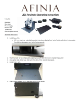
1.3.1
Internal View with Left Housing Cover Removed
1
4
3
5
7
6
2
8
q
Optional EXT PCB board
The optional EXT PCB is added when
installing the optional RTC (Real Time Clock)
kit, dispenser unit or RFID kit.
w
Power supply unit
This is the power board, which is located
behind the main (CONT) PCB. It contains the
transformers, relays, etc., for transference of
electrical current from the supply source to the
control circuits.
e
Interface board
r
Main (CONT) PCB board
The main (CONT) PCB is the primary brain
center for all product activities.
t
Ribbon frame
To support the ribbon supply spindle and
ribbon rewind spindle.
y
Operator panel (KB) PCB board
This PCB provides the user interaction
functionality via the operational buttons and as
well as the LCD.
u
Gearbox
The stepper motor, timing belt and gears in the
gearbox provide the main rotation motion for
precise print positioning.
i
FPGA PCB board
The FPGA (Field Programmable Gate Array)
board is used as a TPH (Thermal Print Head)
controller. It controls the general of printing
such as print strobe and etc. The main purpose
is for history control of printing.

1 Introduction
8
CL4NX Plus/CL6NX Plus Service Manual

9
CL4NX Plus/CL6NX Plus Service Manual
This is supplementary information to Product Settings of the CL4NX Plus/CL6NX Plus operator
manual. For other detailed information on operation and configuration, refer to the CL4NX Plus/CL6NX
Plus operator manual. In this chapter, we only explain the operation and configuration in the Service
menu.
2.1
About Service Menu
In settings mode, the following menus show:
Note
The icon appears between the Information menu and Shortcut menu when the System > Regional >
Display Language Icon menu is enabled. You can easily access the Language menu.
You can find the Service menu in the Tools menu.
However, users cannot access the Service menu
without password. This menu is only for SATO
authorized service personnel use.
2
Operation and
Configuration
Menu Description
Shortcut Directly access frequently used settings.
Printing Access the settings related to printing.
Interface Access the settings related to the interfaces.
Applications Access the settings related to the product command.
System Access the settings related to the display language, buzzer volume etc.
Tools Access the test print, initialization and other settings.
Information Access the product information and help videos.
Tools InformationSystemApplicationsInterfacePrintingShortcut

2 Operation and Configuration
10
CL4NX Plus/CL6NX Plus Service Manual
When you select Service in the Tools menu, the
product shows the Password screen.
You need to enter the correct password in order to
access the menu.
The default password to access the Service menu is
6677.
After a successful login, LOG OUT shows on the
bottom left of the Settings menu screen.
Press the left soft button if you want to log out
immediately.
Note
If no button is pressed for about ten minutes after
login, the login session will end automatically.
Password is required to access the Service menu
again.
2.1.1
Reset Passwords
If you have forgotten the customized password, you can reset it back to the default password.
1 Power off the product.
2 Press and release the power button while pressing and holding the back button,
and buttons simultaneously until the online/offline screen is shown.
All the passwords are reset to their default values.
Note
This key sequence allows users to access the settings menu and the Service menu with the default
passwords as a temporary solution.
After accessing with the default password, you must customize the password again in the System >
Password > Change Password menu.
For more information about changing the password, refer to the CL4NX Plus/CL6NX Plus operator manual.

2 Operation and Configuration
11
CL4NX Plus/CL6NX Plus Service Manual
2.2
Tools Menu Tree Structure
The table below outlines only the tree structure for the Service menu in the Tools menu. Refer to the
tree structure to understand where information is located in the Tools menu. Click on the items in blue to
link directly to the details of the selected items.
Tools Submenus
Test Print
HEX-Dump
Reset
Profiles
Service RFID RFID mode
Module
Region
Inventory Check
Inventory Timeout
Verify
PREND Type 3/4
SRA Setting
NFC Mode
Hide Help Videos
WiFi Ex-
Setting
Wi-Fi Region
WiFi-Direct (only if the wireless LAN module is W-LAN)
Wi-Fi Roam
Adjust
Enable
Roam Threshold
BadAP-list (only if the wireless LAN module is W-LAN)
Supplicant Timeout
SSID Connect Delay (only if the wireless LAN module is
W-LAN)
KeepAlive
AP scan Interval
Back scan (only if the wireless LAN module is W-LAN)
Reset Select Data
Data & Settings
Settings
Counters
Maintenance Printer Serial
USB Serial
Position
Check
Enable
+ Check Value
- Check Value


2 Operation and Configuration
13
CL4NX Plus/CL6NX Plus Service Manual
2.3
Details of the Settings Menu Screen
2.3.1
Tools Menu
The following settings are available in the Tools menu:
Tools
1 Test Print Perform a test print.
2 HEX-Dump Save the hex dump print data or dump data
from the receive buffer to the USB memory.
3 Reset Initialize the settings and counters on the
product.
4
Profiles
Save the product's settings as a profile to be
loaded as needed.
5 Service These are the setting items for service.
Strictly for SATO authorized service personnel
use.
6 Factory These are the setting items for factory.
Strictly for SATO factory personnel use.
7 Certificates Set the wireless LAN authentication.
* Available only if you have installed the USB
memory.
8 Barcode Checker Set the barcode check function using a
barcode checker.
9 Clone Copy the current product settings and data to
the USB memory.
* Available only if you have installed the USB
memory.
10 Support Info Save various information about the product in a
text file to the USB memory.
* Available only if you have installed the USB
memory.
11 Logging Function Save the log data.
12 Startup Guide Enable or disable the startup guide.

2 Operation and Configuration
14
CL4NX Plus/CL6NX Plus Service Manual
Service
Tools > Service
These are the setting items for SATO authorized service personnel used
only.
The setting items are as follows:
1 RFID Set the functions for RFID.
* Shows only if you have installed the optional
RFID kit.
2 NFC Mode Allow you to use NFC function.
3 Hide Help Videos Select the guidance video that you do not wish
to show on the Information > Help screen.
4 WiFi Ex-Setting Set the advanced functions for the wireless
LAN.
* Shows only if you have installed the optional
wireless LAN.
5 Reset Initialize the settings and counter information of
this product.
6 Maintenance Set the Printer Serial or USB Serial manually.
7 Position Check Check the offset position of the label and show
the error.
8 Factory Offset Adjust the offset position.
9 Factory Pitch Adjust the vertical print position.
10 Check SOS
Communication
Check the SOS communication.
* Shows only if you have installed the USB
memory and you have selected Real-Time in
the SOS Mode menu.
11 Copy SOS
DebugLog
Copy the SOS debug log data to the USB
memory.
* Shows only if you have installed the USB
memory.

2 Operation and Configuration
15
CL4NX Plus/CL6NX Plus Service Manual
RFID
Tools > Service > RFID
Set the functions for RFID.
Shows if you have installed the optional RFID kit.
The setting items are as follows:
1 RFID mode Enable or disable the RFID mode.
2 Module Show the type of RFID module installed on the
product.
3 Region Set the region where you use the product.
* Shows only when you have installed the UHF
RFID module.
4 Inventory Check Enable or disable the inventory check function.
* Shows only if you have installed the UHF
RFID module.
5 Inventory Timeout Set the timeout period of the inventory check.
* Shows only when you have installed the UHF
RFID module.
6 Verify Enable or disable the verification of data written
on the tag.
7 PREND Type 3/4 Set the external output signal of the PREND.
8 SRA Setting Configure the detailed settings when executing
SRA (SATO RF Analyze) and check the
antenna (coupler) operation.
* Shows only when you have installed the SRA
available RFID module.
RFID mode
Tools > Service > RFID > RFID mode
Enable or disable the RFID mode.
When RFID mode is set to Enabled, RFID menu is displayed on the
Interface menu.
The options are as follows:
• Enabled: Enable the RFID mode.
• Disabled: Disable the RFID mode.

2 Operation and Configuration
16
CL4NX Plus/CL6NX Plus Service Manual
Module
Tools > Service > RFID > Module
Shows the type of RFID module installed on the product.
Region
Tools > Service > RFID > Region
Set the region where you use the product.
Shows only when you have installed the UHF RFID module.
Select the region (frequency band) where you use the product from the list.
Inventory Check
Tools > Service > RFID > Inventory Check
Enable or disable the inventory check function. Shows only when you have
installed the UHF RFID module.
The options are as follows:
• Enabled: Perform the inventory check of the RFID tag. The product
checks the taken tag number before writing to/read from the tag. An
error occurs when the number is other than one.
• Disabled: Do not perform the inventory check of the RFID tags.

2 Operation and Configuration
17
CL4NX Plus/CL6NX Plus Service Manual
Inventory Timeout
Tools > Service > RFID > Inventory Timeout
Set the timeout period of the inventory check. Shows only if you have
installed the UHF RFID module.
The options are as follows:
•25 ms
•50 ms
•75 ms
•100 ms
•150 ms
•200 ms
•300 ms
•500 ms
Verify
Tools > Service > RFID > Verify
Enable or disable the verification of data written on tag. The options are as
follows:
• Enabled: Perform the verification by reading the data of the written tag.
If not match, the product prints VERIFY TAG ERR on the label.
• Disabled: Do not perform the verification of the written tag.

2 Operation and Configuration
18
CL4NX Plus/CL6NX Plus Service Manual
The timing chart when writing to tag
PREND Type 3/4
Tools > Service > RFID > PREND Type 3/4
Set the output content of the external signal PREND (Print Done).
Reflect the timing of write (stop media feed) of RFID tag to the TYPE3 and
TYPE4 waveforms of PREND (Print End) signal.
The options are as follows:
• Normal: Use the usual PREND signal.
• Motion: Reflect the timing of write (stop media feed) of tag to the
PREND signal.
For the waveforms during the settings of Normal and Motion, refer to the
timing chart below.
Item
Output Waveform
PV
Print end
(PREND)
Print Done
Print motion
Motion Setting Normal Setting
TYPE 1
TYPE 2
TYPE 3
TYPE 4
Print start Write
Feed media
Stop feed Feed media
PV
Print end
(PREND)
Print Done
Print motion
TYPE 1
TYPE 2
TYPE 3
TYPE 4
Print start Write
Feed media
Stop feed Feed media
/