INSTALLATION INSTRUCTIONS
QKK Lock Sets
1-800-355-0157
1-800-355-0157
Morning Industry thanks you for your business and invites you to check out the new and
exciting products on our web site: http://www.morningindustry.com.
NOTE: To view video installation instructions, visit our website at the following address: http://www.morningindusty.com/installvideos.php
Morning Industry thanks you for your business and invites you to check out the new and
exciting products on our web site: http://www.morningindustry.com.
Door Latch
Remote Controller w/2 keys
Back Mounting Plate /4 screws
(2 long screws to attach Cylinder)
(2 short screws to attach Back Module)
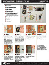
Insert latch in door as
shown in diagram. Make
sure arrow is pointing up.
Prepare Front Assembly
for mounting as follows:
a. insure key is removed.
b. unlock Front Assembly
by putting Flat Driver Bar
in the vertical position.
(see diagram)
Mount Front Assembly
on door, routing wire
loom UNDER latch.
Install Back Mounting
Plate & route wire loom
through bottom
hole.
Select 2 3/8” (60mm) or 2 3/4” (70mm)
from backset template and mark center
of hole on door face.
(Templates provided).
Connect wire loom from
Front Assembly to Back
Module & remove
battery cover. *See Note
Fasten Back Module to
the Back Mounting Plate.
DO NOT OVER
TIGHTEN. Install
premium alkaline
batteries.
Replace Back Module
Cover.
Step 1 Step 2 Step 3
Step 5 Step 6 Step 7
Step 4
NEW DOOR PREPARATION
MARK DOOR
1
VERIFY BACKSET
5
ADJUST LATCH FOR 2 3/4” (70mm) BACKSET
6
INSTALL STRIKE PLATE
4
A
B
B
(A) Close door and mark latch center-
line on door frame. Extend mark
through door frame thickness. Mark at
the center of door frame.
(B) Drill 1” (25.4mm) hole 1/2” (13mm)
deep in door frame.
C
C
A
D
D
(C) Outline the strike plate on door
frame then chisel 1/16” (1.6mm) deep
for a flush fit. Mount strike plate on door
frame.
(1) Verify that backset is a distance
from door edge to center of hole on
door face.
(2) All locks are supplied with adjust-
able latches which fit 2 3/8” (60mm) or
2 3/4” (70mm) backsets.
(A) Latch set for 2 3/8” (60mm)
backset.
(B) Twist flange toward you.
(C) Pull flange out.
(D) Twist flange away from you to set
2 3/4” (70mm) backset.
(D) Adjustable tang on strike permits
bending in or out to eliminate too loose
fit between door and door stop.
CAUTION: To insure proper lockset function, hole
jamb must be drilled a full 1/2” (13mm) deep.
NOTE: Default latch
setting is for 2 3/8”
(60mm) backset.
Drill 2 1/8” (54mm) hole on door
face. Drill 1” (25.4mm) hole in door
edge for the deadbolt latch.
DRILL HOLES
2
(A) Insert latch in hole and keep it
parallel to door face. Mark outline of
face plate and remove latch.
INSTALL LATCH
3
A
(B) Chisel 1/8” (3mm) deep or
until face plate is flush with
door edge.
B
(C) Insert latch and tighten screws.
C
NOTE: Ensure that the bolt is flush with flange at
during all settings.
Front Cylinder Assembly
Latch Strike Plate
Key Pad w/Facia
Back Module
NOTE: Make sure you
install new Strike Plate
on door frame and cut
hole appropriately. It may
be necessary to enlarge
existing hole.
Flat Driver Bar
* Latch and Back
Thumb Turn should
be in unlocked position.
(top of Thumb Turn is
pointing away from latch)
Flange


