Page is loading ...

1
ESC 7550
electronic speed control with reverse
OPERATING
INSTRUCTIONS
Introduction to ESC 7550 Instructions
The following instructions will help you get trouble-free operation
from your electronic speed control (ESC). These simple steps will
allow your ESC to achieve maximum performance and minimize
the chance of problems due to incorrect installation. Consult the
specifications listed below for limitations for this ESC. You should
always ask your hobby dealer or call our service department before
using the ESC for an application other than what is listed in these
instructions. PLEASE FOLLOW ALL INSTRUCTIONS CAREFULLY!
Special Features
✷ The ESC 7550 is designed to be used with up to 75A
peak motors.
✷ Motor, battery, and radio connectors are pre-installed.
✷ High frequency operation provides very smooth
control, maximizes battery run time, and reduces
operating temperatures.
✷ LED indicators (non-setup) are green (neutral), flashing
red for reverse, and red for forward throttle.
✷ Automatic setup – No programming necessary.
✷ Thermal protection – Motor pulses when temperature
reaches 200º F
✷ Led indicators for neutral, full throttle, and full brake.
✷ Aluminum heat sink – Maximum cooling.
✷ Reverse with brakes – Brakes are applied when pushing
forward on trigger. Reverse is applied after releasing
trigger and pushing forward again.
Specifications
Input voltage: 7. 2 – 8 . 4 V
Power output: 75A at 77ºF, 50A at 200ºF
Motor limit: Mabuchi 380
BEC output: 5.0V / 1A
On resistance: 0.005
Size: 33.5 x 27 x 20mm (With heat sink)
Weight: 11.7g
Important Precautions
(ESC = Electronic Speed Control)
✷ Do not run the car near water! Never allow water,
moisture, or any foreign material inside the case of
the ESC.
✷ Never use more than 7 cells (8.4 volts total) in the
battery pack.
✷ Do not attempt to connect the battery pack to the
ESC in reverse, as permanent damage to the ESC
could result.
✷ Do not mix instructions. If you are building a vehicle
that has a mechanical speed control, do not use the
wiring diagram included with the vehicle.
✷ Never cut or splice the ESC input wires. Do not
connect a battery to the receiver’s (Rx) “battery” slot.
The Rx receives power through the ESC itself which
plugs into the Rx’s throttle channel slot.
✷ Always disconnect the battery pack from the ESC when
not in use.
✷ Never turn on the ESC before plugging it into the Rx
and switching on the transmitter (Tx).
✷ Do NOT use LiPo batteries with this ESC.
Mounting the Speed Control
The following information can help the ESC perform at maximum
efficiency and minimize the chance of overheating and radio
interference problems.
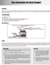
Mounting the Speed Control (Figure 1)
1. Locate the ESC in a position to allow for good airflow, with as
little obstruction from the model’s outer body or exterior dirt
and debris as possible. Maintaining a clean ESC and achieving
good airflow across the unit is very important for keeping the
ESC cool and maximizing performance.
2. Mount the ESC using double-sided mounting tape.
3. Mount the ON/OFF switch in a convenient place. Ensure
that it is securely mounted using mounting tape in a location
where it cannot be easily turned off by objects on the track
or rough terrain.
Mounting the Receiver
1. Radio interference can cause the ESC to rapidly switch
between forward and reverse, overheating the transistors and
possibly damaging the ESC. The Receiver (Rx) and its antenna
should be mounted as far away from the ESC as possible. Also,
try to keep the Rx away from the motor, battery, power wires,
servos, or any large piece of metal - such as a metal chassis.
2. Make sure the Rx antenna can be fully extended through an
antenna tube and not completely enclosed inside the model.
Do NOT cut or coil the Rx antenna.

2
Transmitter Adjustments
Adjusting your transmitter (Tx) is critical for proper speed control
operation. The Tx throttle adjustments are described below:
✷ ATV, EPA, or ATL - set all to maximum.
✷ Throttle Trims and Sub Trims - set all at neutral or zero.
Radio Connector Polarities
The connector included on the
ESC directly fits Futaba receivers.
By simply clipping off the tab on
the side of the connector using
wire cutters, it can be directly
connected to any Airtronics “Z,”
Hitec “S,” or JR receivers. For
proper connection refer to your
radio’s manual.
Motor Preparation
Your motor will require three 0.1µF capacitors to be soldered
as shown. These capacitors will help prevent RF feedback from
adversely affecting the motor.
Speed Control Set-up
1. Switch on the transmitter.
2. Set the throttle trim to the middle setting.
3. Set the throttle reversing switch to the reverse setting.
4. Connect the battery to the ESC.
5. Switch on the ESC, the LED should alternate between red
and orange. This will last a few seconds while the ESC sets
the neutral point.
6. Once the LED is solid you will hear a series of 3 beeps. The
ESC is now set and should work normally.
7. Apply throttle gently to check that the motor is running the
correct direction. If the motor runs backwards, set the throttle
reversing switch to the reverse setting and turn the ESC off /
on again to reset neutral.
Clip off this tab
Troubleshooting Guide
ESC Does Not Work
Problem: Motor and/or steering servo do not move.
1) Recharge dead batteries.
2) Check for faulty power connections.
3) Check for a damaged connection between ESC and Rx.
4) Internal damage. Unit may require service. See “Service
Procedures.”
Problem: No reverse.
1) Tx adjusted incorrectly. Repeat “Transmitter Adjustments.”
2) Improper setup. Repeat “Speed Control Set-Up.”
3) Reverse transistors might be damaged, and unit may
require service. See “Service Procedures.”
Problem: Case is melted.
Internal damage and unit requires service. See “Service
Procedures.”
Problem: ESC runs with switch off.
Unit will require service. See “Service Procedures.”
ESC Works But Other Problems Exist
Problem: Rx glitches or stutters during acceleration.
1) The required motor capacitors are not installed or have
broken. Re-check all capacitors.
2) Rx mounted too close to ESC causing interference.
Relocate Rx away from ESC.
3) Check for faulty power connections.
Problem: Model runs slowly or has no acceleration.
1) The ESC is not set up properly. Repeat Repeat “Speed
Control Set-Up.”
2) Check for faulty battery and/or motor connections.
3) Tx is improperly adjusted. Repeat “Transmitter
Adjustments.”
4) Check that the battery is fully charged.

3
Problem: Steering servo works but motor doesn’t.
1) Motor brushes are hanging up, worn out, or motor is bad.
Clean or replace brushes and check motor.
2) Check for faulty motor connections.
Problem: Overheated motor or hot power plugs.
1) Motor is geared too high. Change to a lower gear setup.
2) Binding in the vehicle’s drive train. Check to make sure
nothing is interfering with the models’ drive train.
3) The motor is shorted electrically. Check the motor for
shorts and replace if necessary.
4) Check for faulty motor connections.
Problem: Motor runs backwards while forward LEDs are on.
1) Motor is wired backwards. Reverse wiring on the motor.
2) A “reverse rotation” motor is being used. Replace motor
with a forward rotation motor.
Problem: Motor runs backwards when forward command is
given, even though LEDs match the motor direction.
Move the Tx throttle reversing switch to the opposite position.
Problem: Model runs properly, then slows or stops.
Check for binding drive train, bad motor or incorrect gear
ratio for track conditions. Adjust gear mesh, replace motor
or change gear ratio.
Service Procedures
Note: ESCs that operate normally when received will be
charged a minimum service fee and return shipping charges.
Before sending your ESC in for service, it is important that you
review the “Troubleshooting Guide” in this instruction sheet.
The ESC may appear to have failed when other problems exist
in the system, such as a defective Tx, Rx or servo, or incorrect
adjustments/installation.
✷ Hobby dealers are not authorized to replace ESCs thought
to be defective.
✷ Do not cut the input harness, switch harness, or power
wires of the ESC before sending it for service. A fee will be
charged for cut wires which must be replaced for testing.
120-Day Limited Warranty
U.S. AND CANADA ONLY
DuraTrax warrants this product to be free from defects in
materials and workmanship for a period of 120 days from the
date of purchase. During that period, we will repair or replace,
at our option, any product that does not meet these standards.
You will be required to provide proof of purchase date (receipt
or invoice).
If, during the 120-day period, your DuraTrax product shows
defects caused by abuse, misuse, or accident, it will be repaired
or replaced at our option, at a service charge not greater than
50% of the current retail list price. Be sure to include your
daytime telephone number in case we need to contact you
about your repair.
This warranty does not cover components worn by use,
application of reverse voltage, cross connections, poor
installation, subjection of components to foreign materials, any
alterations to wires, or tampering. In no case shall our liability
exceed the original cost of the product.
Your warranty is voided if:
A. Reverse voltage is applied to the ESC by connecting
the battery pack backwards, or plugging the motor
connectors into the battery pack.
B. Any wires are allowed to become frayed which could
cause a short.
C. The ESC is subjected to improper voltage on the inputs.
D. Tampering of any electronic components or circuitry
is attempted.
E. Water, moisture, or any other foreign material is allowed
inside the ESC.
Under no circumstances will the purchaser be entitled to
consequential or incidental damages. This warranty gives you
specific legal rights, and you may also have other rights which
vary from state to state. If you attempt to disassemble or repair
this unit yourself it may void the warranty.
For service to your DuraTrax product, either in or out of warranty,
include a detailed description of the problem, return address and
daytime phone number. Please include a copy of the receipt or
invoice and send it post paid and insured to:
Hobby Sevices
3002 N. Apollo Drive, Suite 1
Champaign, IL 61822
(217) 398-0007
www.hobbyservices.com
E-Mail: hobbyservices@hobbico.com
Internet Address: www.duratrax.com
© Copyright 2009 DTXM1270

4
/