Page is loading ...

Emissions Analysis
P/N: 0019-9376 | December 2019 Revision 0
Carbon Monoxide Analyzer
for Exhaust Gas Applications
User
Manual

0019-9376 Revision 0
2
Monoxor
®
XR User Manual
WARRANTY POLICY
Bacharach, Inc. warrants to buyer that at the time of delivery this product will be free from defects in material and
manufacture and will conform substantially to Bacharach, Inc.’s applicable specications. Bacharach’s liability and
buyer’s remedy under this warranty are limited to the repair or replacement, at Bacharach’s option, of this product or
parts thereof returned to seller at the factory of manufacture and shown to Bacharach, Inc.’s reasonable satisfaction to
have been defective; provided that written IMPORTANT of the defect shall have been given by buyer to Bacharach, Inc.
within two (2) years after the date of delivery of this product by Bacharach, Inc.
Bacharach, Inc. warrants to buyer that it will convey good title to this product. Bacharach’s liability and buyer’s remedy
under this warranty of title are limited to the removal of any title defects or, at the election of Bacharach, to the
replacement of this product or parts thereof that are defective in title.
THE FOREGOING WARRANTIES ARE EXCLUSIVE AND ARE GIVEN AND ACCEPTED IN LIEU OF (I) ANY AND ALL
OTHER WARRANTIES, EXPRESS OR IMPLIED, INCLUDING WITHOUT LIMITATION THE IMPLIED WARRANTIES OF
MERCHANTABILITY AND FITNESS FOR A PARTICULAR PURPOSE: AND (II) ANY OBLIGATION, LIABILITY, RIGHT,
CLAIM OR REMEDY IN CONTRACT OR TORT, WHETHER OR NOT ARISING FROM BACHARACH’S NEGLIGENCE,
ACTUAL OR IMPLIED. The remedies of the buyer shall be limited to those provided herein to the exclusion of any
and all other remedies including, without limitation incidental or consequential damages. No agreement varying or
extending the foregoing warranties, remedies or this limitation will be binding upon Bacharach, Inc. unless in writing,
signed by a duly authorized ocer of Bacharach.
Register Your Warranty by Visiting: www.mybacharach.com
SERVICE POLICY
Bacharach, Inc. maintains a service facility at the factory. Some Bacharach distributors / agents may also have repair
facilities; however, Bacharach assumes no liability for service performed by anyone other than Bacharach personnel.
Repairs are warranted for 90 days after date of shipment (sensors, pumps, lters and batteries have individual warranties).
Should your analyzer require non-warranty repair, you may contact the distributor from whom it was purchased or
you may contact Bacharach directly.
If Bacharach is to do the repair work, send the monitor, prepaid, to the closest service center.
Prior to shipping equipment to Bacharach, visit www.mybacharach.com for an Returned Merchandise Authorization
Number (RMA #). All returned goods must be accompanied with an RMA #. Pack the equipment securely (in its original
packing, if possible), as Bacharach cannot be held responsible for any damage incurred during shipping to our facility.
Always include your RMA #, shipping address, telephone number, contact name, billing information and a description
of the defect as you perceive it. You will be contacted with a cost estimate for expected repairs prior to the performance
of any service work. For liability reasons, Bacharach has a policy of performing all needed repairs to restore the
monitor to full operating condition.
IMPORTANT
Product improvements and enhancements are on-going, therefore the specications and information contained in
this document may change without IMPORTANT.
Bacharach, Inc. shall not be liable for errors contained herein or for incidental or consequential damages in connection
with the furnishing, performance, or use of this material.
No part of this document may be photocopied, reproduced, or translated to another language without the prior
written consent of Bacharach, Inc.
Copyright © 2019, Bacharach, Inc., All Rights Reserved.
BACHARACH, Fyrite®, True Spot, Monoxor®, and B-Smart® are registered trademarks of Bacharach, Inc. All other trademarks, trade names, service
marks and logos referenced herein belong to their respective companies.

0019-9376 Revision 0
3
Monoxor
®
XR User Manual
Contents
Overview ........................................................... 5
1.1 Introduction ...................................................................................................................... 5
1.2 Iconography ...................................................................................................................... 5
1.3 General Safety Statements ............................................................................................. 6
1.4 Product Overview ............................................................................................................ 6
1.5 Components ................................................................................................................... 11
1.6 Features .......................................................................................................................... 12
1.7 Monoxor
®
XR Sales Combinations ............................................................................... 13
1.8 Specications ................................................................................................................. 13
Setup ............................................................... 15
2.1 Connecting the Probe .................................................................................................... 15
2.2 Front Panel Buttons ....................................................................................................... 16
2.3 Power Options ................................................................................................................ 17
2.4 Turning on the Monoxor
®
XR ........................................................................................ 19
Conguration ................................................. 20
3.1 Menu Structure Overview ............................................................................................. 20
3.2 The Warm-Up Sequence ................................................................................................ 20
3.3 Main Menu ...................................................................................................................... 21
3.4 Ambient CO Menu ......................................................................................................... 23
3.5 DierentialTemperatureMenu ................................................................................... 25
3.6 Memory Options Menu ................................................................................................. 26
3.7 Setup Menu .................................................................................................................... 27
3.8 Calibration Menu ........................................................................................................... 35
3.9 Diagnostics Menu .......................................................................................................... 36
3.10 Status Menu .................................................................................................................... 37
Operation ........................................................ 38
4.1 Overview ......................................................................................................................... 38
4.2 Taking a Gas Sample ...................................................................................................... 39
4.3 The RUN and Hold Screens ........................................................................................... 40
4.4 CO Trending Graph ........................................................................................................ 41

0019-9376 Revision 0
4
Monoxor
®
XR User Manual
4.5 Ending a Test .................................................................................................................. 42
4.6 DierentialTemperatureMeasurement .................................................................... 42
4.7 Timed Ambient CO Testing ........................................................................................... 43
4.8 Printing Using the Optional IrDA Printer .................................................................... 44
4.9 TurningOtheAnalyzer ............................................................................................... 46
4.10 PC Interface and Fyrite
®
User Software ...................................................................... 47
Care & Maintenance ...................................... 48
5.1 Serviceability .................................................................................................................. 48
5.2 Cleaning the Probe ........................................................................................................ 49
5.2.1 Equipment Required ..................................................................................................................................49
5.2.2 Procedure .................................................................................................................................................... 50
5.3 Filter Replacement ......................................................................................................... 51
5.4 CO Sensor Replacement ................................................................................................ 52
5.4.1 Accessing the CO Sensor ............................................................................................................................ 52
5.4.1 CO Sensor Replacement Procedure .........................................................................................................53
5.4.2 B-Smart
®
CO Sensor Replacement ...........................................................................................................54
5.5 Temperature Calibration .............................................................................................. 55
5.5.1 Materials Required ..................................................................................................................................... 55
5.5.2 Temperature Calibration Procedure ........................................................................................................ 55
5.6 CO Sensor Calibration ................................................................................................... 57
5.6.1 Materials Required ..................................................................................................................................... 57
5.6.2 CO Manual Zero Procedure ......................................................................................................................57
5.6.3 CO Sensor Span Procedure .......................................................................................................................58
5.7 T-Ref Sensor Calibration ............................................................................................... 59
Troubleshooting ............................................. 60
6.1 Error and Warning Messages ....................................................................................... 60
6.2 Replacement Parts......................................................................................................... 61
6.3 Accessories ..................................................................................................................... 61
6.4 InstrumentIdentication ............................................................................................. 62
Additional Information ................................. 63
7.1 Bacharach Combustion App ......................................................................................... 63
7.2 Service Centers ............................................................................................................... 63

0019-9376 Revision 0
5
Monoxor
®
XR User Manual
1. Overview
1.1 Introduction ..................................................................................................................... 6
1.2 Iconography ...................................................................................................................... 7
1.3 General Safety Statements ............................................................................................. 7
1.4 Product Overview ............................................................................................................ 8
1.5 Components ................................................................................................................... 12
1.6 Features .......................................................................................................................... 14
1.7 Monoxor
®
XR Sales Combinations ............................................................................... 15
1.8 Specications ................................................................................................................. 15
1.1 Introduction
Thank you for investing in a Bacharach Monoxor
®
XR Carbon Monoxide (CO) Analyzer.
To assure proper use and operator safety, please read the contents of this manual for
important information on the operation and maintenance of the analyzer.
IMPORTANT: Before using this product, carefully read and strictly follow the
instructions in the manual.
1.2 Iconography
Alert Icon Description
DANGER
Imminently hazardous situation which, if not avoided, will result
in death or serious injury.
WARNING
Potentially hazardous situation which, if not avoided, could
result in death or serious injury.
WARNING
Potential electrical shock hazard which, if not avoided, could
result in death or serious injury.
WARNING
Hot surface which, if not avoided, could result in physical injury
or damage to the product.
CAUTION
Potentially hazardous situation which, if not avoided, could result
in physical injury or damage to the product or environment. It
may also be used to alert against unsafe practices.
IMPORTANT
Additional information on how to use the product.

0019-9376 Revision 0
6
Monoxor
®
XR User Manual
1.3 General Safety Statements
WARNING: This analyzer is not intended to be used as a safety device.
WARNING: When testing a combustion system, a full visual inspection should be
performed to ensure its safe operation.
CAUTION: This analyzer is not intended to be used on a continuous basis.
CAUTION: Do not store instrument or its sensors with solvents or products that
contain solvents.
CAUTION: Except for sensor and battery replacement, this analyzer should only be
opened and/or serviced by authorized Bacharach personnel. Failure to comply may
void the warranty.
HAZARDOUS AREA WARNING: This instrument has not been designed to be
intrinsically safe for use in areas classied as hazardous locations. For your safety, DO
NOT use it in hazardous (classied) locations.
CAUTION: Do not use ammable or combustible substances (like carburetor uid used
for cleaning the probe) near an open ame.
CAUTION: When the instrument is used in an inecient oil-fueled appliance where
there is a high emission of soot, the probe’s sample lter may become clogged. Before
every use check the lter to conrm it is clean or replace it with a new lter.
1.4 Product Overview
The Monoxor
®
XR is a portable hand-held carbon monoxide (CO) analyzer for use in
commercial and industrial applications. It is intended to be used by:
• Engine & service technicians
• Maintenance personnel
• Safety inspectors
• Propane forklift operators
to detect and display concentrations of CO gas between 0 and 80,000 ppm. The analyzer is
capable of testing for CO in both ambient room air and in the exhaust stream of fossil-fuel
red combustion systems.

0019-9376 Revision 0
7
Monoxor
®
XR User Manual
Ambient CO
CO gas is colorless, odorless, and deadly. Test CO levels in suspect Pambient air. Perform
an automated 15-minute test, watch live values, or view a dynamic CO graph over time.
Fig. 1-1: Perform an Ambient CO test and watch live values, or view a dynamic CO graph over
time
The analyzer detects and displays the presence of CO by rst drawing in a gas sample from
the area being tested by the analyzer’s built-in motorized pump. The gas sample is next
directed into a sensor chamber where the sample is analyzed for the presence of CO. If
CO is detected, the CO ppm level is given on the analyzer’s main display. A trending screen
(accessible from the RUN screen by using the right or left arrow key) shows dynamic CO levels
graphed over a programmable time period (from 30 seconds to 15 minutes). In addition to the
visual notications, you can set a CO alarm limit, above which an audible alarm buzzer will
beep repeatedly. An audible alarm with a slower beep frequency occurs when the batteries
are low.
A backlight enables the operator to read the display in dimly-lit areas. The displays and
menus are available in multiple languages (English, French and Spanish).
A permanent record of the detected CO level, along with the current time and date, can be
made by using the optional wireless IrDA printer. Test records can also be saved in memory.

0019-9376 Revision 0
8
Monoxor
®
XR User Manual
An ambient CO feature takes approximately 15-minutes to complete and provides a minute-
by-minute snapshot of CO readings, as well as a “Max CO” value that represents the highest
CO reading measured during the entire test. Results can be saved to memory and/or printed.
A calibration reminder can be set to occur every 6, 8, 10, 12, or 15-months after the last
calibration. (Select “Never” to disable this feature.) Regular calibration periods of 6 months to 1
year are recommended. The calibration reminder value sets a time period after which the
analyzer displays a calibration reminder message during warm-up.
To avoid the need for manual CO sensor calibrations, the B-Smart
®
Sensor program is
supported with the Monoxor
®
XR. After enrolling in the program, pre-calibrated replacement
B-Smart
®
CO sensors are shipped at predetermined intervals of your choice.
• Choose a program start date that best suites your needs.
• Receive a pre-calibrated B-Smart
®
sensor.
• Return your old sensor in a returnable, pre-labeled container.
Benets include no downtime, self calibration, convenience, and cost savings. For additional
information about the B-Smart
®
Calibration Program, contact Bacharach at 1-800-736-4666
or email [email protected].
A programmable inactivity timeout causes the analyzer to initiate shutdown mode if no key
presses occur for the specied time period. If the analyzer initiates automatic shutdown or
is turned OFF manually while a high level of CO is still present within the unit, the automatic
CO purge feature forces the analyzer’s pump to remain on until the detected CO level drops
below 50 ppm.
The instrument is supplied with the following components:
• Probe and hose assembly
• Four disposable “AA” alkaline batteries
• Hard carrying case
• Factory-calibrated and installed CO sensor
Depending on the model and kit, some or all of the following components are included:
• Spare lters
• Fyrite
®
User Software (FUS)
• USB cable (type A to mini B)
• Infrared Data Association (IrDA) printer with four disposable “AA” alkaline batteries
• Printer paper
Using the optional thermocouples, ambient and ue gas temperatures can be measured.
Additionally, the Monoxor
®
XR can calculate a dierential temperature based on two
sampled temperatures (T1 and T2) using the optional stack thermocouple or optional probe
assembly (with built-in thermocouple). After you take the two sample readings, the dierential
value (T1-T2) is calculated, optionally saved in memory, displayed on the main run screen,
and is shown on printouts.

0019-9376 Revision 0
9
Monoxor
®
XR User Manual
Fig. 1-2: Dierential value is calculated, saved in memory, displayed on the main run screen,
or shown on printouts

0019-9376 Revision 0
10
Monoxor
®
XR User Manual
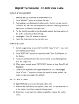
Fig. 1-3: Components of the Optional Probe Assembly
# Description
1 Temperature Port
2 USB Port
3 Sample Gas Port
4 Sample Gas Hose
5 USB Cable (Optional)
6 Water Trap and Filter Assembly
7 Probe Handle
8 Probe Tube
1
2
3
4
5
6
7
8

0019-9376 Revision 0
11
Monoxor
®
XR User Manual
1.5 Components
Fig. 1-4: Components of the Optional Probe Assembly
# Description
1 Monochrome Display (LCD) with Backlight
2
Function Keys (F1, F2, F3)
• Context sensitive
• Functions shown at bottom of display
3
Up and Down Arrow Keys
• Scroll up / down through a list
• Increase / decrease alphanumeric values
4
5
Left and Right Arrow Keys
• Scroll left / right through a eld
• Jump to top / bottom of list
• Access the trending screen
6
7
Enter Key
• Choose highlighted item
• Accept value / character
8
Escape Key
• Cancel most operations and display
previous screen
9
Power / Backlight Key
• Press & release: Power ON
• Press & release: Toggle backlight ON / OFF
• Press & hold (2 secs): Begin power
OFF sequence
10
Run / Hold Key
• While in HOLD: Turn on pump,
display RUN screen, and begin test.
• While in RUN: Turn o pump, display
HOLD screen and last set of test data.
• In most menus: Display HOLD screen.
• During power down: Return display
to HOLD screen (cancel power down).

0019-9376 Revision 0
12
Monoxor
®
XR User Manual
1.6 Features
Sensors
• Field-replaceable electrochemical sensor (B-Smart
®
CO)
• Temperature measurement using a Type K thermocouple (with probe assembly 19-7111)
Power
• 4 × AA alkaline batteries (included)
• 4 × AA lithium batteries
• 4 × AA rechargeable batteries (externally charged)
• Low battery warning
Testing Features
• Complete test results (100 sets) can be stored, recalled, displayed, and printed
• Time and date stamping of test results
• Dierential temperature
• Secure calibration function (password protected)
• Auto power-o feature with sensor purge feature
• Status and diagnostic menus
• Ambient CO
UserCustomizations
• Multi-language interface
• Auto/Manual zero functions for the CO sensor
• Customized user information (3 × lines of 20 characters)
• Customized logo on printouts (192 × 384 pixels)
• Temperature unit selection
Hardware
• Exhaust probe / standard probe with hose assembly for gas transport
• Sample pump to provide gas sample delivery
• Backlit monochrome graphic LCD
• Hard carrying case
• USB 2.0 (mini-B connection) for PC interface and communications
PC Interface
• USB cable (Type A to Mini B)
• Fyrite
®
User Software (FUS) (Windows compatible)

0019-9376 Revision 0
13
Monoxor
®
XR User Manual
1.7 Monoxor
®
XR Sales Combinations
Components
Basic & Standard
Probe
(P/N: 0019-8119)
Reporting &
Standard Probe
(P/N: 0019-8120)
Basic & Exhaust
Probe
(P/N: 0019-8121)
Reporting &
Exhaust Probe
(P/N: 0019-8122)
Standard Probe
Exhaust Probe
Temperature
Quick Start Guide
B-Smart
®
CO
Sensor
Hard Case
Printer
PC Software
USB Cable
1.8 Specications
Measurement Range Resolution Accuracy Response Time (T90)
CO 0 to 80,000 ppm 20 ppm
±20 ppm (0 to 200 ppm)
±10% reading (201 to 80,000)
< 40 sec
Temp
-20° to 650° C
(-4° to 1202° F)
1° C
(1° F)
±2° C (0° to 124° C)
±3° C (125° to 249° C)
±4° C (250° to 400° C)
< 50 sec

0019-9376 Revision 0
14
Monoxor
®
XR User Manual
Specication Description
Temperature
Storage: -20° to 50° C ( -4° to 122° F ) | 0° to 20° C ( 32° to 68° F ) optimal
Operation: -5° to 45° C (23° to 113° F)
Reference: 20° ± 2° C (68° ± 4° F)
Humidity
Storage: 15 to 90% RH, non-condensing
Operation: 15 to 95% RH, non-condensing
Reference: 45 ± 10% RH, non-condensing
Pressure 1 atmosphere ± 10%
Weight 16 ounces (454 g) with batteries
Dimensions (H × W × D) 8.0” × 3.6” × 2.3” (20.3 cm × 9.1 cm × 5.8 cm)
Warm-up Time 60 seconds
Gas Sample Flow Rate 300 to 700 cc/min
Sensors
CO Sensor: Electrochemical (P/N: 0024-0997)
B-Smart CO Sensor: Electrochemical (P/N: 0024-1795)
Temperature: K-Type thermocouple
Product Approvals and
Regulatory Compliance
EN50270: 2015 (CE Mark) EMC tested in accordance with European Directive
RoHS Compliance
Case Construction
High impact ABS plastic with co-molded rubber.
Optional protective rubber boot with molded-in magnets.
Display Monochrome with backlight
USB Connector Mini B (USB 2.0)
Memory 100 locations for storing test results
IrDA Port
Protocol: IrDA-SIR Data Bits: 8 Stop Bits: 1
Baud Rate: 9600 Parity: None
Power Supply Options Batteries (4 AA)
Type: Disposable Alkaline (Included)
Duration: 15 hours min, continuous max draw
Type: Disposable Lithium
Duration: 20 hours, continuous max draw
Type: Rechargeable
Duration: 8 hours, continuous max draw

0019-9376 Revision 0
15
Monoxor
®
XR User Manual
2. Setup
2.1 Connecting the Probe ................................................................................................... 17
2.2 Front Panel Buttons ....................................................................................................... 18
2.3 Power Options ................................................................................................................ 19
2.4 Turning on the Monoxor
®
XR ....................................................................................... 21
2.1 Connecting the Probe
A rigid stainless steel probe with handle is connected to a exible hose with an integral
water trap/lter and is used to draw a gas sample into the analyzer from the room,
grilles, diusers, and furnace ues.
1. Inspect the exible hose for cracks. If a hose is defective, replace the entire probe assembly.
2. Before using the analyzer, check that the water trap/lter is clean and dry. If necessary,
dry out the trap and replace the lter element.
3. Push the probe’s “sample gas” tubing onto the GAS inlet connector.
Fig. 2-1: Connecting the Probe

0019-9376 Revision 0
16
Monoxor
®
XR User Manual
2.2 Front Panel Buttons
Fig. 2-2: Front Panel Buttons
# Description
1
• Powers the analyzer ON and OFF. Hold this button down for at least 2 seconds to turn the
power OFF.
• Toggles the backlight ON and OFF while the analyzer is turned ON.
2
• UP (
), DOWN ( ), LEFT ( ), and RIGHT ( ) arrows are context-specic navigation buttons for
the menus.
• UP ( ) and DOWN ( ) arrow buttons scroll to menu options that are hidden from view
(when a side scroll bar is displayed indicating additional information).
• UP ( ) and DOWN ( ) arrow buttons cause the displayed value to increase or decrease
accordingly.
• LEFT ( ) and RIGHT ( ) arrow buttons jump to the top and bottom of lists, respectively.
• LEFT ( ) and RIGHT ( ) arrow buttons position the active cursor on specic elements of a value to
be changed.
• LEFT ( ) arrow button displays the CO Trending screen from the Run/Hold screen.
• RIGHT ( ) arrow button displays the QR code screen from the hold screen.
3 • The ENTER button. Performs the action selected.
4
• While in the HOLD screen, turns the sample pump on, displays the RUN screen, and
begins a test.
• While in the RUN screen, turns the sample pump o, displays the HOLD screen and the
last set of data.
• Displays the HOLD screen while pressing it from most menus.
• Returns the display to the HOLD screen while pressing it during the shutdown sequence.
5 • The ESC button cancels most operations and displays the previous screen.
6
• Pressing function keys accepts the corresponding function dened above that key at the
bottom of the display (for example, PRINT, SAVE, MENU, etc.).

0019-9376 Revision 0
17
Monoxor
®
XR User Manual
2.3 Power Options
Power options include:
• Disposable AA alkaline batteries (included)
• Disposable AA lithium (Li) batteries
• Externally charged rechargeable NiMH batteries.
Check the Monoxor
®
XR for sucient power prior to each use. Replace the batteries if the
low (or replace) battery symbol appears in the upper right corner of the Monoxor
®
XR screen.
Batteries
(4 AA, Fresh or Fully Charged)
Estimated Life Span in Hours
(Continuous, Pump On)
Alkaline (disposable) 15 hours
Lithium (disposable) 20 hours
Rechargeable 8 hours
Replace batteries as follows:
1. Remove the battery cover from the back of analyzer.
2. If old batteries are installed, remove them and properly discard them.
3. Observing the polarity markings inside the battery compartment, install four ‘AA’
disposable (alkaline or lithium) batteries or four fully-charged (externally charged) AA
rechargeable NiMH batteries.
4. Replace the battery cover.
NOTE: The Monoxor
®
XR does NOT charge rechargeable batteries.
NOTE: The Monoxor
®
XR sounds a series of beeps to indicate that the batteries
need to be replaced.

0019-9376 Revision 0
18
Monoxor
®
XR User Manual
Fig. 2-3: Removing the Battery Cover

0019-9376 Revision 0
19
Monoxor
®
XR User Manual
2.4 Turning on the Monoxor
®
XR
To turn on the Monoxor
®
XR, press the PWR button.
NOTE: After turning on the Monoxor
®
XR, it performs a warm-up procedure
which includes an auto-zero procedure (when in Auto Zero mode) for the sensors
(see section 1.8 and 3.7). For this reason, be sure to turn on the Monoxor
®
XR in a
clean air environment. When the analyzer is in CO Manual mode, the analyzer
will indicate the background CO during startup.

0019-9376 Revision 0
20
Monoxor
®
XR User Manual
3. Conguration
3.1 Menu Structure Overview ............................................................................................ 22
3.2 The Warm-up Sequence ................................................................................................ 22
3.3 Main Menu ...................................................................................................................... 23
3.4 Ambient CO Menu ......................................................................................................... 25
3.5 DierentialTemperatureMenu ................................................................................... 27
3.6 Memory Options Menu ................................................................................................. 28
3.7 Setup Menu .................................................................................................................... 29
3.8 Calibration Menu ........................................................................................................... 37
3.9 Diagnostics Menu .......................................................................................................... 38
3.10 Status Menu ....................................................................................................................... 39
3.1 Menu Structure Overview
Menus and the items contained within them are described in a top-down fashion, starting
from the startup screens and working sequentially through the menus and menu items.
3.2 The Warm-Up Sequence
Menus and the items contained within them are described in a top-down fashion, starting
from the startup screens and working sequentially through the menus and menu items.
Boot Sequence Description
Splash screen shows the Bacharach logo with version, model
number, and serial number information. This screen is displayed
for approximately 3 seconds.
Splash screen shows the Bacharach logo with version, model
number, and serial number information. This screen is displayed
for approximately 3 seconds.
/