V-ZUG 64004 Installation guide

Category
Cooker hoods
Type
Installation guide

V-ZUG 64004 is a versatile range hood designed for both extraction and recirculation modes, offering flexible options for kitchen ventilation. With its powerful motor and efficient airflow system, it effectively removes cooking fumes, odors, and grease particles from the air, creating a fresher and healthier cooking environment. The range hood's sleek design and customizable installation options make it a stylish and functional addition to any modern kitchen.

V-ZUG 64004 is a versatile range hood designed for both extraction and recirculation modes, offering flexible options for kitchen ventilation. With its powerful motor and efficient airflow system, it effectively removes cooking fumes, odors, and grease particles from the air, creating a fresher and healthier cooking environment. The range hood's sleek design and customizable installation options make it a stylish and functional addition to any modern kitchen.

Installation instructions
Range hood
Mode: Extraction / Recirculation
DSTS9
1011458-04
20/04/2021
1011458-04
1
The appliance should be installed by qualified personnel only.
Each step must be carried out and checked in full in the order specified.
Validity
64004 (DSTS9, construction width 90 cm)
General notes
Identification plate
Remove the grease filters. The identification plate is located on the inside of the appliance.
Installation accessories supplied
All fixing elements are contained in the scope of delivery.
Mains cable 12 self-tapping screws 3.5 × 9.5mm
Lower angle bracket 6 screws M4 × 8mm
Upper angle bracket 6 screws 4 × 15mm
Angle brackets
(are not used)
Accessories: Recirculation box
Extraction mode
The extracted air must not be fed into a chimney which is used for exhausting fumes from appliances burning gas or
other fuels.
Observe the local fire regulations.
Recirculation mode
The air outlet grille must not be covered during operation.
Installation instructions
Range hood
Mode: Extraction / Recirculation
DSTS9
1011458-04
20/04/2021
1011458-04
2
Dimensions
Cannot be installed in conjunction with a gas hob.
Recessed installation variant Flush installation variant
120
8
8
0
7
6
5
4
116
65
8
0
2
250
102
98
332
(ø150)
≥660
≥30
8
1
2
108
-1
30
3
1
2
10–200
646
2.4
400
332
16617
R
0
5
124
R5
884
108
812
7
884
812
108
7
124
R5
108
7
124
4
4
R0–5
R0–5
1 The fan can be rotated for mounting. The exhaust air can thus be extracted upwards, left, right or downwards. The fan can also
be mounted in the same position at the back of the appliance. If the fan is mounted at the back of the appliance, the back panel
of the cabinet has to be cut out in the mounting area and sufficient installation space must be provided behind the cabinet.
2 The electrics can, if required, be positioned to the left of the fan, on the hood body or in the cabinet.
3 Ensure that the material is sufficiently stable.
4 Stepped milling required if installed flush in a work surface made of natural stone (granite, marble).
Exhaust air connection ø150mm.
Installation instructions
Range hood
Mode: Extraction / Recirculation
DSTS9
1011458-04
20/04/2021
1011458-04
3
Installation
Carefully insert the hood body 1 in the prepared cut-out 2 (see
Dimensions).
For flush installation, level the hood body at the right height (us-
ing spacer set H6.0330).
1
2
Fasten the lower brackets 3 to the housing 5 of hood body 1 us-
ing two screws 4 for each bracket so that the feet 6 rest on the
base of the cabinet.
The brackets can also be rotated for mounting.
1
3
4
6
5
3.5×9.5 mm
Installation instructions
Range hood
Mode: Extraction / Recirculation
DSTS9
1011458-04
20/04/2021
1011458-04
4
Loosely fasten the upper brackets 7 to the housing 5 of the
hood body 1.
The brackets can be adjusted. Push the brackets 7 up and fasten
in place under the worktop 8 using screws 24.
Tighten screws 9 on the housing 5.
Alternatively, the brackets can also be rotated for mounting so that
the hood body can be fastened to the side of the cabinet.
9
24
1
7
8
5
Level the hood body 1 and secure the brackets 3 to the base of
the cabinet using screws 10.
1
3
10
2x
4x15 mm
Installation instructions
Range hood
Mode: Extraction / Recirculation
DSTS9
1011458-04
20/04/2021
1011458-04
5
Run the connecting cable 11 from the hood body 1 to the motor
housing 12 and plug it into the fan 13.
Lay the cable 11 and fitted with the cable bushing 14 supplied
insert into the cable receptacle in the housing 5.
13
1
14
12
11
Alternatively, the motor housing 12 can be mounted to the hood
body from the back.
To do this, remove the back cover 21 from the housing 5 and
mount at the front.
Insert the connecting cable 11 fitted with the cable bushing 14
into the cable receptacle in the back opening of the housing 5.
Installation instructions
Range hood
Mode: Extraction / Recirculation
DSTS9
1011458-04
20/04/2021
1011458-04
6
Turn the motor housing 13 so that the exhaust connection 15
points in the desired direction and fasten it to the housing 5.
13
15
3.5×9.5 mm
M4×8 mm
5
Insert the three connecting cables 16, which exit the housing
from the underside of the range hood 5, into the corresponding
couplings 17 on the underside of the control unit 18.
Make sure that the connectors engage firmly. Close the middle
connector lock.
5
17
18
16
Installation instructions
Range hood
Mode: Extraction / Recirculation
DSTS9
1011458-04
20/04/2021
1011458-04
7
Moisture ingress in the cabinet could lead to a risk of electric shock. The connection box must, therefore, have no
contact with the floor. The cable must be laid and secured in a suitable place.
Insert the mains cable 19 supplied into the socket 20 on the un-
derside of the control unit 18.
19
20
18
Fasten the control unit 18 to the range hood using screws.
The connection box can be mounted in the position shown.
Alternatively, it can be mounted on the other side of the fan, on the
back of the range hood or on a cabinet panel.
18
3.5×9.5 mm
Installation instructions
Range hood
Mode: Extraction / Recirculation
DSTS9
1011458-04
20/04/2021
1011458-04
8
For flush installation:
Use cementing-in set for flush installation, art. no. 86392885.
Raise the range hood.
Apply sealant and allow sealant joints to dry completely.
Extraction mode
There is a danger of toxic fumes developing if the range hood is operated at the same time as an ambient air-depend-
ent firing system!
Fasten exhaust ducting 22 to exhaust connection 23.
Flat channels and hoses are available as accessories (see section
19.4 of the planning aid).
22
23
Only use smooth pipes or flexible duct hoses made from non-flammable materials for exhaust ductwork.
To achieve the greatest possible air extraction with the lowest noise levels, please note the following:
The diameter of the exhaust duct must not be less than 150mm.
If flat exhaust channels are used, the cross section should not be smaller than that of the exhaust air connection.
The exhaust ducting should be as short and straight as possible.
Only use elbows with large radii.
The exhaust ducting must not be kinked or compressed.
Make sure that all connections are secure and airtight.
Installation instructions
Range hood
Mode: Extraction / Recirculation
DSTS9
1011458-04
20/04/2021
1011458-04
9
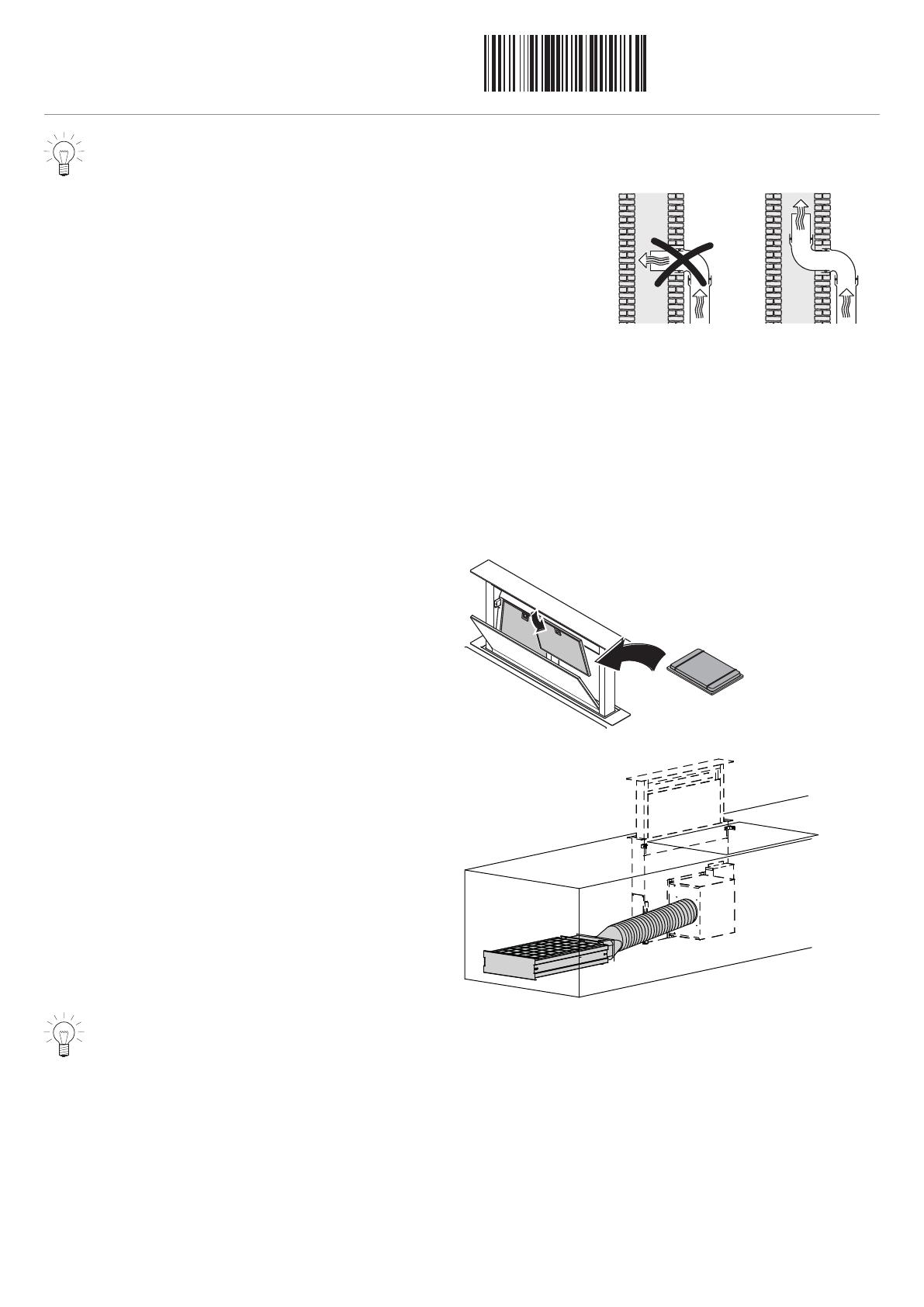
Any constriction of the airflow will reduce extraction performance and increase operating noise.
If the exhaust duct is to be routed outdoors, we recommend in-
stalling a telescopic wall box (accessory available for purchase).
If the exhaust air is to be ducted into a chimney flue, the intake
piece must be aligned with the flow direction of the flue.
If the exhaust duct runs horizontally, a gradient of at least 1cm per metre must be observed. This would prevent the ingress of con-
densation into the range hood.
If the exhaust duct runs through cool rooms, lofts, etc., there may be sharp variations in temperature in individual areas. Sweating or
condensation is to be expected. This makes it therefore necessary to insulate the exhaust ducting.
Recirculation mode
For recirculation mode with recirculation box, ensure access for maintenance purposes and also ensure the blow-out opening is at least
500cm² (e.g. base recess or lamella base).
If an exhaust air connection is not structurally possible, the range hood must be set up for recirculation operation. There are several
possibilities to do this:
Recirculation mode integrated in appliance (DSTS only)
Connect the exhaust air connector with the recirculation air con-
version set.
Fit the metal grease filters of the range hood with the long-life
activated charcoal filter (see the «Cleaning and care» section in
the operating instructions).
Recirculation mode with recirculation box
Connect the recirculation box to the exhaust connection.
The activated charcoal filters are integrated in the recirculation
box. Activated charcoal filters are not used in the range hood.
For ventilation accessories, see the planning aid.
The conversion kits are available for order as accessories.
  • Page 1 1
  • Page 2 2
  • Page 3 3
  • Page 4 4
  • Page 5 5
  • Page 6 6
  • Page 7 7
  • Page 8 8
  • Page 9 9

V-ZUG 64004 Installation guide

Category
Cooker hoods
Type
Installation guide

V-ZUG 64004 is a versatile range hood designed for both extraction and recirculation modes, offering flexible options for kitchen ventilation. With its powerful motor and efficient airflow system, it effectively removes cooking fumes, odors, and grease particles from the air, creating a fresher and healthier cooking environment. The range hood's sleek design and customizable installation options make it a stylish and functional addition to any modern kitchen.

Ask a question and I''ll find the answer in the document

Finding information in a document is now easier with AI