Hitachi RAS-10FSNM Installation & Maintenance Manual
- Category
- Split-system air conditioners
- Type
- Installation & Maintenance Manual
This manual is also suitable for

Installation
&
Maintenance
Manual
INVERTER-DRIVEN
SPLIT SYSTEM
HEAT PUMP
AIR CONDITIONERS
- DC INVERTER UTOPIA IVX -
Model:
Outdoor Unit;
RAS-8FSNM
RAS-10FSNM
RAS-12FSNM
IMPORTANT:
READ AND UNDERSTAND
THIS MANUAL BEFORE
USING THIS HEAT-PUMP
AIR CONDITIONERS.
KEEP THIS MANUAL FOR
FUTURE REFERENCE.
P00104Q
(Q)
(Q)
(Q)

i
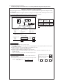
IMPORTANT NOTICE
l HITACHI pursues a policy of continuing improvement in design and performance of products. The right is
therefore reserved to vary specifications without notice.
l HITACHI cannot anticipate every possible circumstance that might involve a potential hazard.
l This heat pump air conditioner is designed for standard air conditioning only. Do not use this heat pump
air conditioner for other purposes such as drying clothes, refrigerating foods or for any other cooling or
heating process.
l The installer and system specialist shall secure safety against leakage according to local regulations or
standards. The following standards may be applicable if local regulations are not available.
British Standard, BS4434 or Japan Standard, KHKS0010.
l No part of this manual may be reproduced without written permission.
l Signal words (DANGER, WARNING and CAUTION) are used to identify levels of hazard seriousness.
Definitions for identifying hazard levels are provided below with their respective signal words.
: Immediate hazards which WILL result in severe personal injury
or death.
: Hazards or unsafe practices which COULD result in severe personal
injury or death.
: Hazards or unsafe practices which COULD result in minor personal
injury or product or property damage.
: Useful information for operation and/or maintenance.
l It is assumed that this heat pump air conditioner will be operated and serviced by English speaking
people. If this is not the case, the customer should add safety, caution and operating signs in the native
language.
l If you have any questions, contact your distributor or dealer of HITACHI.
l This manual gives a common description and information for this heat pump air conditioner which you
operate as well as for other models.
l Perform installation work according to local codes and regulations.
l This heat pump air conditioner has been designed for the following temperatures. Operate the heat pump
air conditioner within this range.
NOTE
This manual should be considered as a permanent part of the air conditioning equipment and should
remain with the air conditioning equipment.
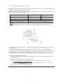
Temperature
(
o
C)
Maximum Minimum
Cooling Indoor 23 WB 15 WB
Operation Outdoor 43 DB -15 DB
Heating Indoor 30 DB 15 DB
Operation Outdoor 17 WB -20 WB
DB: Dry Bulb, WB: Wet Bulb

ii
SAFETY SUMMARY
l Use refrigerant R410A in the refrigerant cycle. Do not charge oxygen, acetylene
or other flammable and poisonous gases into the refrigerant cycle when performing a
leakage test or an air-tight test. These types of gases are extremely dangerous and
can cause an explosion. It is recommended that compressed air, nitrogen or
refrigerant be used for these types of tests.
l Do not pour water into the indoor or outdoor unit. These products are equipped with
electrical parts. If poured, it will cause a serious electrical shock.
l Do not touch or adjust safety devices inside the indoor or outdoor units. If these
devices are touched or readjusted, it may cause a serious accident.
l Do not open the service cover or access panel for the indoor or outdoor units without
turning OFF the main power supply.
l Refrigerant leakage can cause difficulty with breathing due to insufficient air. Turn OFF
the main switch, extinguish any naked flames and contact your service contractor, if
refrigerant leakage occurs.
l The installer and system specialist shall secure safety against refrigerant leakage
according to local regulations or standards.
l Use an ELB (Electric Leakage Breaker). In the event of a fault, there is danger of an
electric shock or a fire if it is not used.
l Do not install the outdoor unit where there is a high level of oil mist, flammable gases,
salty air or harmful gases such as sulphur.
l Do not use any sprays such as insecticide, lacquer, hair spray or other flammable
gases within approximately one (1) meter from the system.
l If circuit breaker or fuse is often activated, stop the system and contact your service
contractor.
l Do not perform installation work, refrigerant piping work, drain piping and electrical
wiring connection without referring to our installation manual. If the instructions are
not followed, it may result in a water leakage, electric shock or a fire.
l Check that the ground wire is securely connected. If the unit is not correctly grounded,
it lead electric shock. Do not connect the ground wiring to gas piping, water piping,
lightning conductor or ground wiring for telephone.
l Connect a fuse of specified capacity.
l Do not put any foreign material on the unit or inside the unit.
l Make sure that the outdoor unit is not covered with snow or ice, before operation.
l Before performing any brazing work, check to ensure that there is no flammable
material around.
When using refrigerant be sure to wear leather gloves to prevent cold injuries.
l Protect the wires, electrical parts, etc. from rats or other small animals.
If not protected, rats may gnaw at unprotected parts and which may lead to a fire.
l Fix the cables securely. External forces on the terminals could lead to a fire.

iii
SAFETY SUMMARY
l Do not install the indoor unit, outdoor unit, remote control switch and cable within
approximately 3 meters from strong electromagnetic wave radiators such as medical
equipment.
l Supply electrical power to the system to energize the oil heater for 12 hours before
start-up after a long shutdown.
l Do not step or put any material on the product.
l Provide a strong and correct foundation so that;
a. The outdoor unit is not on an incline.
b. Abnormal sound does not occur.
c. The outdoor unit will not fall down due to a strong wind or earthquake.
NOTE:
l It is recommended that the room be ventilated every 3 to 4 hours.
l The heating capacity of the heat pump unit is decreased according to the outdoor air
temperature. Therefore, it is recommended that auxiliary heating equipment be used in
the field when the unit is installed in a low temperature region.

iv
CHECKING PRODUCT RECEIVED
l Upon receiving this product, inspect it for any shipping damage.
Claims for damage, either apparent or concealed, should be filed immediately with the shipping
company.
l Check the model number, electrical characteristics (power supply, voltage and frequency) and
accessories to determine if they are correct.
The standard utilization of the unit shall be explained in these instructions.
Therefore, the utilization of the unit other than those indicated in these instructions is not recommended.
Please contact your local agent, as the occasion arises.
Hitachi's liability shall not cover defects arising from the alteration performed by a customer without
Hitachi's consent in a written form.
This product shall not be mixed with general household waste at the end of its life and it
shall be retired according to the appropriated local or national regulations in an environmentally
correct way Due to refrigerant, oil and other components contained in the Air Conditioner,
its dismantling must be done by a professional installer accordingly to the applicable
regulations.
ATTENTION :
Contact the Hitachi Customer Care for more information.
!

v
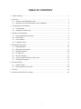
TABLE OF CONTENTS
1. Safety Summary....................................................................................................................... 1
2. Structure................................................................................................................................... 1
2.1 Outdoor Unit & Refrigerant Cycle .................................................................................... 1
2.2 Necessary Tools and Instrument List for Installation ....................................................... 3
3. Transportation and Handling .................................................................................................... 4
3.1 Transportation ................................................................................................................. 4
3.2 Handling of Outdoor Unit ................................................................................................. 4
4. Outdoor Unit Installation........................................................................................................... 5
4.1 Factory-Supplied Accessories ......................................................................................... 5
4.2 Initial Check ..................................................................................................................... 5
4.3 Service Space ................................................................................................................. 6
4.4 Installation Work .............................................................................................................. 8
5. Refrigerant Piping Work ......................................................................................................... 10
5.1 Piping Materials ............................................................................................................. 10
5.2 Refrigerant Piping Work ................................................................................................ 11
5.3 Piping Connection ......................................................................................................... 13
5.4 Air Tight Test.................................................................................................................. 15
5.5 Vacuum Pumping .......................................................................................................... 16
5.6 Caution of the Pressure by Check Joint ........................................................................ 18
5.7 Collecting Refrigerant .................................................................................................... 19
6. Electrical Wiring ...................................................................................................................... 19
6.1 General Check .............................................................................................................. 19
6.2 Electrical Wiring Connection ......................................................................................... 20
7. Test Run ................................................................................................................................. 24
8. Safety and Control Device Setting.......................................................................................... 28

1
l Do not perform installation work, refrigerant
piping work, drain piping and electrical
wiring connection without referring to the
installation manual.
l Check that the ground wire is securely
connected.
l Connect a fuse of specified capacity.
Do not install the indoor unit, outdoor unit,
remote control switch and cable within
approximately 3 meters from strong
electromagnetic wave radiators such as
medical equipment.
1. Safety Summary
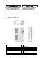
2. Structure
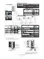
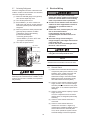
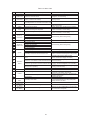
2.1 Outdoor Unit & Refrigerant Cycle
<Outdoor Unit>
No. Part Name No. Part Name
1 Compressor
2 Heat Exchanger
3 Propeller Fan 13
4 Fan Motor 14
High Pressure Switch for Protection
5 Strainer 15 High Pressure Sensor
6 Distributor 16 Check Valve
7 Reversing Valve 17 Solenoid Valve
8 Micro-Computer Control Expansion Valve 18 Crankcase Heater
9 Stop Valve for Gas Line 19
Air Outlet
10 Stop Valve for Liquid Line 20 Air Inlet
11 Accumulator 21
12
Electrical Box
Low Pressure Sensor

2
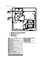
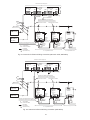
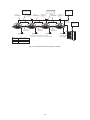
<Refrigerant Cycle>
Discharge Gas
Thermistor
Thermistor
Ambient
Thermistor
Discharge Gas Thermistor
Compressor
Heat Exchanger
Sensor for Regrigerant Pressure
Oil Separator
Accumulator
8
10
12
8
10
12
Strainer(3/8)
Strainer(1/2)
Strainer(3/4)
Distributor
Reversing Valve
Capillary Tube
Electronic Expansion Valve
Check Valve
Solenoid Valve
Solenoid Valve
Check Joint
Stop Valve for Liquid Line
Stop Valve for Gas Line
High Pressure Switch for Protection
<Outdoor Unit>

3
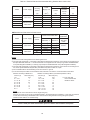
2.2 Necessary Tools and Instrument List for Installation
Use tools and measuring instruments only for the new refrigerant which is directly touch to refrigerant.
No. Tool No. Tool No. Tool No. Tool
1 Handsaw 6 Copper Pipe Bender 11 Spanner 16 Leveller
2
Phillips
Screwdriver
7
Manual Water Pump
12
Charging Cylinder
17
Clamper for Solder-
less Terminals
3 Vacuum Pump 8 Pipe Cutter 13 Gauge Manifold 18
Hoist
(for Indoor Unit)
4
Refrigerant Gas
Hose
9 Brazing Kit 14 Cutter for Wires 19 Ammeter
5 Megohmmeter 10 Hexagon Wrench 15 Gas Leak Detector 20 Voltage Meter
G: Interchangeability is available with current R22 l: only for Refrigerant R410A (No Interchangeability with R22)
5: Prohibited F: only for Refrigerant R407C (No Interchangeability with R22)
R410A R407C
Pipe Cutter
Chamfering Reamer
G G
-
Cutting Pipe
Removing Burrs
Flaring Tool G l G * The flaring tools for R407C are applicable to R22. Flaring for Tubes
* If using flaring tube, make dimension of tube
larger for R410A.
* In case of material 1/2H, flaring is not available.
Pipe Bender
G G
* In case of material 1/2H, bending is not available.
Use elbow for bend and braze.
Bending
Expanding Tool
G G
* In case of material 1/2H, expanding of tube is not
available. Use socket for connecting tube.
Expanding Tubes
l G *
For
12.7
,
15.88
,
s
p
anner size is u
p
2mm.
G G
*
For
6.35, 9.53, 19.05, spanner size is
the same.
Brazing Tool G G * Perform correct brazing work. Brazing for Tubes
Nitrogen Gas
G G
* Strict Control against Contamin
(Blow nitrogen during brazing.)
Prevention from
Oxidation during
Brazing
Lubrication Oil
(for Flare Surface)
* Use a synthetic oil which is equivalent to the oil
used in the refrigeration cycle.
Applying Oil to the
Flared Surface
* Synthetic oil absorbs moisture quickly.
* Check refrigerant cylinder color. Refrigerant Charging
H
Liquid refrigerant charging is required regarding
zeotoropic refrigerant.
Vacuum Pump
G G
H
Vacuum Pumping
Adapter for
Vacuum Pump
l F
Manifold Valve
l F
* No interchangeability is available due to higher
pressures when compared with R22.
Charging Hose
l F
H
Do not use current ones to the different refrigerant.
If used, mineral oil will flow into the cycle and cause
sludges, resulting in clogging or compressor failure.
Connection diameter is different; R410A: UNF1/2,
R407C: UNF7/16.
Charging Cylinder 5 5 * Use the weight scale. -
Weight Scale
G G -
Measuring
Instrument for
Refrigerant Charging
Refrigerant Gas
Leakage Detector
l F
* The current gas leakage detector (R22) is not
applicable due to different detecting method.
Gas Leakage Check
T: Interchangeability with R407C.
Vacuum Pumping,
Vacuum Holding,
Refrigerant Charging
and Check of
Pressures
l F
l F
Measuring Instrument and Tool
Interchangeability
with R22
Reason of Non-Interchangeability and Attention
(H: Strictly Required)
Torque Wrench
Vacuum
Drying
.
Refrigerant
Charge
Refrigerant
Cylinder
The current ones are applicable. However, it is
required to mount a vacuum pump adapter which
can prevent from reverse flow when a vacuum
pump stops, resulting in no reverse oil flow.
Use
Refrigerant
Pipe
Extrusion
Adjustment Gauge
l
-
Connection of
Flare Nut
Dimensional Control
for Extruded Portion
of Tube after Flaring
TT
T

4
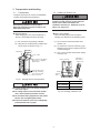
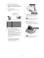
3. Transportation and Handling
3.1 Transportation
Transport the product as close to the installation
location as practical before unpacking.
Do not put any material on the product.
Apply two lifting wires onto the outdoor unit,
when lifting it by crane.
3.2 Handling of Outdoor Unit
Do not put any foreign material into the
outdoor unit and check to ensure that none
exists in the outdoor unit before the
installation and test run. Otherwise, a fire or
failure, etc. may occur.
Fig. 3.1 Hanging Work for Transportation
Over 60
o
Wire Rope
0.7 to 1.0m
Do not remove the plastic
band or the corrugated
paper frame.
Pass the wire ropes
through each lifting
hole in the wooden
base as shown.
l Hanging Method
When hanging the unit, ensure a balance of
the unit, check safety and lift up smoothly.
(1) Do not remove any packing materials.
(2) Hang the unit under packing condition with
two (2) ropes, as shown in Fig. 3.1.
l Lift the outdoor unit in its factory packaging
with 2 wire ropes.
l For safety reasons ensure that the outdoor
unit is lifted smoothly and does not lean.
l Do not attach lifting equipment to the plastic
band or the corrugated paper frame.
l Ensure the exterior of the unit is adequately
protected with cloth or paper.
l When Using Handles
When manually lifting the unit using the
handles, pay attention to the following points.
(1) Do not remove the wooden base from
outdoor unit.
(2) To prevent the unit from overturning, pay
attention to the center of gravity as shown
in the below figure.
(3) Two or more personnel should be used to
move the unit.
Fig. 3.2 Handling of Outdoor Unit
Approx. 20
o
410
620
Wooden
Base
Handle
Center of Gravity
Fall Angle of
This Product
(kg)
Model Unit Gross Weight
RAS-8FSNM(Q)
RAS-10FSNM(Q)
179
RAS-12FSNM(Q) 182

5
4. Outdoor Unit Installation
4.1 Factory-Supplied Accessories
Check to ensure that the following accessories
are packed with the outdoor unit.
If any of these accessories are not packed with
the unit, please contact your contractor.
Table 4.1 Factory-Supplied Accessories
4.2 Initial Check
• Install the outdoor unit where good ventilation is
available, and where it is dry.
• Install the outdoor unit where the sound or the
discharge air from the outdoor unit does not
affect neighbors or surrounding vegetation.
The operating sound at the rear or right/left
sides is higher than the value in the catalog at
the front side.
• Check to ensure that the foundation is flat, level
and sufficiently strong.
• Do not install the outdoor unit where there is a
high level of oil mist, salty air or harmful gases
such as sulphur.
• Do not install the outdoor unit where the
electromagnetic wave is directly radiated to the
electrical box.
• Install the outdoor unit as far as practical, being
at least 3 meters from the electromagnetic
wave radiator.
• When installing the outdoor unit in snow-
covered areas, mount the field-supplied hoods
at the discharge side of the outdoor unit and
the inlet side of the heat exchanger.
• Install the outdoor unit where it is in the shade
or it will not be exposed to direct sunshine or
direct radiation from high temperature heat
source.
• Do not install the outdoor unit where dust or
other contamination could block the outdoor
heat exchanger.
• Install the outdoor unit in a space with limited
access to general public.
Aluminum fins have very sharp edges. Pay
attention to the fins to avoid any injury.
NOTE
NOTE
Direction of Strong Wind
Direction of Air Discharge
• Do not install the outdoor unit in a space where
a seasonal wind directly blows to the outdoor
heat exchanger or a wind from a building space
directly blows to the outdoor fan.
• In case of installation in the open spaces
unavoidably where there is no buildings or
surrounding structures, adopt the wind guard
set or install near the wall to avoid facing the
wind directly. Ensure that the service space
should be secured.
(1) Using Wind Guard
(2) A Wall to Guard Against Wind
NOTE:
If the extreme strong wind blows directly against
the air discharge portion, the fan may rotate
reversely and be damaged.
Install the outdoor unit on a roof or in an area
where people except service engineers can not
touch the outdoor unit.
Wing Guard Set
(Optional)
Strong Wind
Model
WSP-335A
Q'ty
2
Secure the adequate
service space.
Direction of Strong Wind
Air Intake Side
Face the air discharge
side to the wall.
Wall
Accessory Q'ty
Pipe with Flange
of Refrigerant Piping
1
Compressed Sheet 1

6
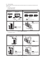
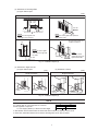
4.3 Service Space
Install the outdoor unit with a sufficient space around the outdoor unit for operation and maintenance as
shown below.
(1) Obstacles on Inlet Side
(a) Upper Side is Open.
(b) Obstacles in Above
Fig. 4.1 Installation Space (1)
Fig. 4.2 Installation Space (2)
Min. 100
Single Installation Multiple Installation
(mm)
NOTE:
Open both right and left sides.
NOTE:
Mount the airflow guide
and open both right and
left sides.
* Around sides
are closed.
* Around sides
are open.
Min.100
Min.300
Min.50
Front
Side
Min.300
Front Side
Min.100
Front Side
Min. 360
A
L
H
Min. 360
A
L
NOTE:
Mount the airflow guide
and open both right and
left sides.
Fit positions " " with unit front side.
Min.200
Front Side
Single Installation Multiple Installation
(mm)
No more than 2 units for
multiple installation
Min.
1000
Max. 300
Min. 360
H
Min. 360
Min. 100
Min.
1000
H
Max. 300
NOTE:
Open both right and
left sides.
NOTE:
Mount the airflow guide
and open both right and
left sides.
Min.
1000
Max. 300
Min. 360
H
L
A
Min. 100
Min.
1000
H
Max. 300
L
A
Min. 360
NOTE:
Mount the airflow guide
and open both right and
left sides.

7
(2) Obstacles on Discharge Side
(a) Upper Side is Open.
(3) Obstacles in Right and Left
(a) Upper Side is Open. (b) Obstacles in Above
(mm)
Min. 500
Min. 50
Single Installation
L
Min. 500
Min. 100
L
(mm)
Single Installation
Min. 500
Min. 50
L
Min. 1000
Min. 500
L
Min. 1000
Min. 100
If L is larger than H, mount the units on a base so
that H is greater or equal to L.
H: Unit Height (1650mm) + Base Concrete Height
In this situation ensure that the base is closed and does not allow the airflow to short circuit.
In each case, install the outdoor unit so that the discharge flow is not short-circuited.
NOTE
Fig. 4.3 Installation Space (3)
Fig. 4.4 Installation Space (4)
Min. 150
Single Installation Multiple Installation
(mm)
NOTE:
Mount the airflow guide and open both
right and left sides.
NOTE:
Mount the airflow guide
and open both right and
left sides.
Min.
700
Front
Side
Min. 700
H
Min. 700
Min. 100
Min. 700
NOTE:
Mount the airflow guide and
open right end or left end.
H
350
No more than 2 units for
multiple installation
NOTE:
Mount the airflow
guide and open both
right and left sides.
350
L
L
Min.50Min.100
Fit positions " " with unit front side.
L A
0 < L
< 1/2H 600 or more
1/2H < L < H 1400 or more

8
(4) Multi-Row and Multiple Installations
Keep a distance of more than 15mm between
other units and do not put obstacles on the right
and left sides. Dimension B is as shown below.
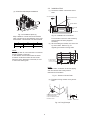
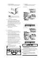
4.4 Installation Work
(1) Secure the outdoor unit with the anchor
bolts.
Fig. 4.6 Installation of Anchor Bolts
Fix the outdoor unit to the anchor bolts by
special washer of factory-supplied
accessory.
(2) When installing the outdoor unit, fix the unit
by anchor bolts. Refer to Fig. 4.7
regarding the location of fixing holes.
(3) Example of fixing outdoor unit by anchor
bolts.
Max.
21mm
A
ir Flow Direction
Anchor Bolt
M12
Base of Outdoor Unit
Nut
Special Washer
Filled Mortar
Concrete
Cut this portion when this type
of anchor bolt is used.
If not, it is difficult to remove
the service cover.
Concrete Anchor Bolt
Max. 21mm
(After cut "A " )
A
NOTE:
When the mark * dimension is secured, piping
work from bottom side is easy without
interference of foundation.
Fig. 4.7 Position of Anchor Bolts
NOTE:
If L is larger than H, mount the units on a base so
that H is greater or equal to L.
In this situation ensure that the base is closed
and does not allow the airflow to short circuit.
When the mark * dimension is secured, be sure
to mount the airflow guide.
L
L
Min. 3000
(*Min. 600)
Min. 600
A
B
Fig. 4.5 Installation Space (5)
L A B
0 < L
< 1/2H 600 or more 300 or more
1/2H < L < H 1400 or more 350 or more
Fig. 4.8 Fixing Example
*170
100
470
42025 25
570
265
265
100
4-φ16x23.5 Hole
for Anchor Bolt

9
(4) Fix the outdoor unit firmly so that declining,
making noise, and falling down by strong
wind or earthquake is avoided.
75
1101173
Fixing Plate
(Field-Supplied)
Both sides on the unit fixing
can be possible.
When vibration measures
are necessary,
add vibration proof rubber.
(Field-Supplied)
Fig. 4.10 Frame and Base Installation
Fig. 4.9 Additional Fixing Arrangement
(5) When installing the unit on a roof or a
veranda, drain water sometimes turns to
ice in a cold morning. Therefore, avoid
draining in an area where people often use
because it is slippery.
(6) In case of the drain piping is necessary for
the outdoor unit, use the drain-kit
(DBS-26 or DBS-26L: Optional Parts).
Base Width of Outdoor Unit
100mm
Frame Width 60mm
(Field-Supplied)
Frame
Incorrect
Outdoor Unit
is Unstable.
Metal Plate
100mm or more
Metal Plate
Correct
Frame
Base Width of Outdoor Unit
100mm
Outdoor Unit
is Stable.
Recommended Metal Plate Size (Field-Supplied)
Material: Hot-Rolled Mild Steel Plate (SPHC)
Plate Thickness: 4.5T
120
420
(560)
70 70
20
4-C10
2-Long Hole
14
60
R
(7) The whole of the base of the outdoor unit
should be installed on a foundation. When
using vibration-proof mat, it should also be
positioned the same way.
When installing the outdoor unit on a field-
supplied frame, use metal plates to adjust
the frame width for stable installation as
shown in Fig. 4.10.
36016539668
127 6673
Drain Hole
(3-φ24)
Air Inlet
Drain Hole (2-φ26)
(Drain Boss Attaching Position)

10
5. Refrigerant Piping Work
Use refrigerant R410A in the refrigerant cycle.
Do not charge oxygen, acetylene or other
flammable and poisonous gases into the
refrigerant cycle when performing a leakage
test or an air-tight test. These types of gases
are extremely dangerous and can cause an
explosion. It is recommended that
compressed air, nitrogen or refrigerant be
used for these types of tests.
5.1 Piping Materials
(1) Prepare locally-supplied copper pipes.
(2) Select the piping size from the Table 5.1.
(3) Select clean copper pipes. Make sure
there is no dust and moisture inside of the
pipes. Blow the inside of the pipes with
nitrogen or dry air, to remove any dust or
foreign materials before connecting pipes.
l Cap the end of the pipe when the pipe is to
be inserted through a hole.
l Do not put pipes on the ground directly
without a cap or vinyl tape at the end of the
pipe.
NOTE
l Cautions for Refrigerant Pipe Ends
When installing pipe through
the wall, secure a cap at the
end of the pipe.
Correct
CorrectIncorrect Incorrect
Correct Incorrect
HoleHole
Attach a cap
or vinyl tape.
Attach a cap
or vinyl tape.
Attach a cap
or vinyl bag with
rubber band.
Do not place the pipe
directly on the ground.
Rain water can
enter.
B
Flare Nut
l Flaring Dimension
Perform the flaring work as shown below.
l Piping Thickness and Material
Use the pipe as below.
l Flare Nut Dimension
Use the flare nut as below.
Material is based on a JIS standard (JIS B8607).
(T) It is impossible to perform the flaring
work with 1/2H material. In this case,
use an accessory pipe (with a flare).
0.4 ~ 0.8R
A
d
90
o
+
2
o
45
o
+
2
o
(mm)
+0
-0.4
R410A
6.35 9.1
9.53 13.2
12.7 16.6
15.88 19.7
19.05 (T)
Diameter
d
A
(mm)
R410A
Thickness Material
6.35
0.8 O material
9.53
0.8 O material
12.7
0.8 O material
15.88
1.0 O material
19.05
1.0 1/2H material
22.2
1.0 1/2H material
25.4
1.0 1/2H material
28.6
1.0 1/2H material
Diameter
<Flare Nut Dimension B (mm)
Diameter R410A
6.35
17
9.53
22
12.7
26
15.88
29
19.05
36
Dimension is based on a JIS standard
(JIS B8607).

11
5.2 Refrigerant Piping Work
(1) Ensure that the directions for refrigerant piping work according to the tables.
Table 5.2 Limitation of Outdoor Unit
Table 5.1 Indoor Unit Type List
Length
Model Gas (*1) Liquid
RAS-8FSNM(Q)
9.53
( 12.7 (*2))
RAS-10FSNM(Q)
RAS-12FSNM(Q)
(*1): The accessory pipe with flange is attached.
(*2): Select the liquid piping size of 12.7 when the piping length is more than 70m. only for RAS-8FSNM(Q)
Outer Diameter and
Piping Size (mm)
Maximum Piping Length
Maximum Lift between
Outdoor Unit and Indoor Unit
25.4
12.7
Actual Length ≤ 100m
Equivalent Length ≤ 125m
Outdoor Unit is higher than Indoor Unit: ≤ 50m
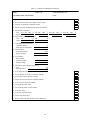
Indoor Unit is higher than Outdoor Unit: ≤ 40m
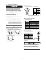
Combination between Indoor Unit and Outdoor Unit
Indoor Unit Type
In-the-Ceiling
In-the-Ceiling
Low Height
4-Way Cassette
2-Way Cassette
Wall
Floor
Floor Conncealed
Ceiling
Available
Nominal Horsepower (HP)
1.00.8 2.01.5 3.02.5 4.03.3 8.05.0 10.0
2.3
A maximum total capacity of 130% and a minimum total capacity of 50% can be obtained
by combination of the indoor units when compared with the nominal outdoor unit capacity.
Table 5.2 System Combination
Outdoor Unit Model
Minimum
Combination
Capacity
Maximum
Combination
Capacity
Combination
Quantity
Minimum
Individual
Operation
Capacity
22.2
19.05
HP HP HP
4.0
5.0
6.0
10.4
13.0
15.6
0.8
0.8
0.8
Indoor Unit
(*1) A total capacity of 100% must be obtained by combination of the indoor units when compared
with the nominal outdoor unit capacity, if only one indoor unit is combined.


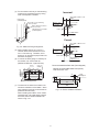
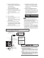
5.3 Piping Connection
Pipes can be connected from 4 directions.
Fig. 5.1 Piping Direction
Front Side
Piping Cover
Rear Side
Piping Cover
Rear Side Piping Wor
k
(Knock-Out Hole)
Right Side Piping Work
(Knock-Out Hole)
Bottom Side
Piping Work
(Piping Cover)
Front Side
Piping Work
(Knock-Out Hole)
Rear Side
Piping Cover
Hold down
the cover
slowly.
Front Side
Piping Cover
Rear Cover
Remove the screws with holding down the
cover. If not, the cover may fall down
(It weights approx. 5kg.).
13
8FSNM(Q)
10FSNM(Q)
12FSNM(Q)
8
10
12
FSNM(Q)
FSNM(Q)
FSNM(Q)
0.8 1.5
2.0
2.5 5.0
8.0
10.0
8
10 12
8
10 12

14
(1) Confirm that the valve is closed.
(2) Prepare a field-supplied bend pipe for
liquid line. Connect it to the liquid valve by
flare nut through the square hole of bottom
base.
(3)
Double Spanner Work Tightening Work for Stop Valve
Do not apply the double
spanner work here.
Refrigerant leakage shall
occur.
For Piping Connection
When tightening the flare nut, use two
spanners.
Pipe Size Tightening Torque for Flare Nut
6.35 (1/4)
20N-m
9.53 (3/8)
40N-m
12.7 (1/2)
60N-m
15.88 (5/8)
80N-m
19.05 (3/4)
100N-m
Pipes can be connected from 4 directions
as shown Fig. 5.1. Make a knock-out hole
in the front pipe cover or bottom base to
pass through the hole.
After removing the pipe cover from the unit,
punch out the holes following the guide line
with screwdriver and a hammer.
Then, cut the edge of the holes and attach
insulation (Field-Supplied) for cables and
pipes protection.
(a) Front and Right Side Piping Work
Select the correct knock-out size
depending on whether it is for power
wiring or transition wiring.
It is available to correct the liquid or gas
piping, power wiring less than 14mm
2
and transition wiring from “A” part.
NOTE:
When using conduit, check to the tube
size before removing “B” part.
(b) Bottom Side Piping Work
After removing bottom of the piping
cover, perform piping and wiring works.
B
A
Front Side Piping Hole
Right Side Piping Hole
NOTE:
Prevent the cables from coming into
direct contact with the piping.
Conduit
Gas Piping
Liquid Piping
Screw
Piping Cover
Bottom Base
Bottom Side Piping Hole
(4)
Page is loading ...
Page is loading ...
Page is loading ...
Page is loading ...
Page is loading ...
Page is loading ...
Page is loading ...
Page is loading ...
Page is loading ...
Page is loading ...
Page is loading ...
Page is loading ...
Page is loading ...
Page is loading ...
Page is loading ...
-
 1
1
-
 2
2
-
 3
3
-
 4
4
-
 5
5
-
 6
6
-
 7
7
-
 8
8
-
 9
9
-
 10
10
-
 11
11
-
 12
12
-
 13
13
-
 14
14
-
 15
15
-
 16
16
-
 17
17
-
 18
18
-
 19
19
-
 20
20
-
 21
21
-
 22
22
-
 23
23
-
 24
24
-
 25
25
-
 26
26
-
 27
27
-
 28
28
-
 29
29
-
 30
30
-
 31
31
-
 32
32
-
 33
33
-
 34
34
-
 35
35


Hitachi RAS-10FSNM Installation & Maintenance Manual
- Category
- Split-system air conditioners
- Type
- Installation & Maintenance Manual
- This manual is also suitable for
Ask a question and I''ll find the answer in the document
Finding information in a document is now easier with AI
Related papers
-
Hitachi RAM-280FSPH Inverter Driven Multi-Split System Air Conditioner User manual
-
-
-
-
Hitachi RAS-(4-12)HNC(1)(E) User manual
-
Hitachi RAM-8MQ Inverter-Driven Multi-Split System Air Conditioners User manual
-
-
-
-
Other documents
-
Daikin B73-391 Installation guide
-
Mitsubishi MUZ-FD12NA Installation guide
-
Airwell YUDA060 User manual
-
Fujitsu UTCOGPRFUBD2 Installation guide
-
-
Fujitsu ASGA30FUTA-B Installation guide
-
Fujitsu AOGG48CRTA-U Installation guide
-
-
Fujitsu AOGG36CBTA-U Installation guide
-