PAC RPK4-GM2301 User manual

Type
User manual

PAC RPK4-GM2301 is a complete radio replacement kit with vehicle information retention for select 11-Bit GMLAN Vehicles. It features a user-friendly LCD display with onboard buttons to view and adjust vehicle information and settings. The included radio replacement interface retains factory steering wheel controls and allows programming of two radio functions to each button using short press/long press dual command functionality. It also provides data bus driven outputs like retained accessory power, illumination, vehicle speed sensor, reverse trigger, and parking brake.

PAC RPK4-GM2301 is a complete radio replacement kit with vehicle information retention for select 11-Bit GMLAN Vehicles. It features a user-friendly LCD display with onboard buttons to view and adjust vehicle information and settings. The included radio replacement interface retains factory steering wheel controls and allows programming of two radio functions to each button using short press/long press dual command functionality. It also provides data bus driven outputs like retained accessory power, illumination, vehicle speed sensor, reverse trigger, and parking brake.

Complete Radio Replacement Kit with
Vehicle Information Retention for
Select 11-Bit GMLAN Vehicles
RPK4-GM2301
Pacific Accessory Corporation
Rev. 072517
Page 1
© 2017 AAMP Global. All rights reserved. PAC is a Power Brand of AAMP Global.
PAC-audio.com
Parts List
The RPK4-GM2301 includes everything you need for a professional installation of an aftermarket radio in your 11-Bit GM
Vehicle.
This kit contains:
1. Dash kit
1a. (x1) Double DIN mounting panel
1b. (x1) Single DIN radio ISO mount trim ring
1c. (x1) LCD adapter bracket (for single DIN applications)
1d. (x1) Pocket (for single DIN applications)
1e. (x8) Radio mounting screws
1f. (x1) USB cover (for when USBDMA1 or USBDMA6 is not used with our kit)
1g. (x2) Radio mounting brackets (one left and one right)
2. Radio replacement interface module
3. Radio connection harnesses
4. PAC-LCD
Overview
The RPK4-GM2301 is a complete radio replacement kit with vehicle information retention for select 11-Bit GMLAN Vehicles. This kit utilizes a
user friendly LCD display with onboard buttons to view and adjust vehicle information and settings. The included radio replacement interface
will retain factory steering wheel controls (SWC) and allows you to program two radio functions to each SWC button by using short press long
press dual command functionality. The interface also provides data bus driven outputs such as retained accessory power (RAP), illumination,
vehicle speed sensor (VSS), reverse trigger and parking brake.
Table of Contents: Page:
1. Factory Radio Removal --------------------------------------------------------- 2
2. Radio Replacement Installation and Wiring Instructions --------------- 3
3.
Steering Wheel Control Programming --------------------------------- 3-4
4. Dash Kit Assembly --------------------------------------------------------------- 5
5. Using the PAC-LCD -------------------------------------------------------------- 6
1. If a double DIN radio is being installed with this kit, enough wire has been supplied to mount the LCD in the glove box or center console area.
2. The interface comes pre-programmed for all of the vehicle’s factory SWC functions and does not require programming, unless you wish to
re-assign the SWC functions, or utilize short press long press dual command functionality. The SWC can always be restored to default settings
by pressing and releasing the program button on the side of the interface once and waiting 7 seconds for the LED to ash 3 times.
3. The LED will ash whenever a SWC button is pressed.
4. The Interface has the ability to retain the warning chimes and audible turn signal clicks through its onboard piezo. This feature is on by default.
This can be disabled using the supplied PAC-LCD. For more info on disabling the chimes through the module see page 6.
Important Notes
1a.
3.
1d.
1c.
2.
1b.
4.
1e.
1f.
1g.
Complete Radio Replacement Kit with
Vehicle Information Retention for
Select 11-Bit GMLAN Vehicles
RPK4-GM2301
Pacific Accessory Corporation
Rev. 072517
Page 2
© 2017 AAMP Global. All rights reserved. PAC is a Power Brand of AAMP Global.
PAC-audio.com
Removing the factory radio from the vehicle
2004 - 2007 Chevrolet Malibu / Malibu Max / 2008 Chevrolet Malibu Classic
1. Carefully unclip the thin side trims from both the left and right side of the radio trim bezel.
2. Remove the (2) 9/32 screws from below the driver side under-dash panel.
3. Unclip and remove the side edge panel from the left side of the dash.
4. Remove the (2) 9/32 screws securing the left side of the driver side under-dash panel.
5. Unclip the wire harness from the side trim of the drivers side under-dash panel.
6. Using a panel removal tool, carefully pry downward on the panel at the bottom of the drivers side under-dash panel. (There are (3) panel
clips).
7. Using a panel removal tool, unclip the top edge of the drivers side lower dash panel and lower out of the way.
8. Lower the glove box door all the way down.
9. Remove the single 9/32 screw from the middle of the glove box door latch bar.
10. Remove the (4) 9/32 screws securing the glove box dash section to the sub-dash.
11. Carefully remove the side panel from the right side of the dash.
12. Repeat steps 4 and 5 above for the right side of the dash.
13. Unclip and lower the panel below the glove box and remove the single 9/32 screw from the lower left side of the glove box panel.
Remove the glove box and panel.
14. Starting from the bottom of the radio/HVAC control trim bezel, pull bezel outward to unfasten.
15. Disconnect the hazard harness from the radio/climate control bezel and remove bezel.
16. Loosen the (2) 9/32 screws securing the HVAC controls.
17. Remove the (4) 9/32 screws securing the radio to the sub-dash.
18. Carefully pull radio upward and outward, disconnect the wire harness and antenna lead to remove radio.
2005 - 2006 Chevrolet Cobalt
1. Carefully pop the trim above the glove box with a panel removal tool. Remove trim at the top left of dash bezel.
2. Remove the dash panel with a panel removal tool. Note: Dash panel clips are very tight.
3. Disconnect the wire harness behind dash panel.
4. Remove the (4) 9/32 screws securing the radio to the sub-dash.
5. Carefully pull the radio upward and outward, disconnect the wire harness and antenna lead to remove radio.
2005 - 2009 Pontiac G6
1. Remove side trim panels from both driver and passenger side dash with a panel removal tool.
2. Remove (2) 9/32 screws on both driver and passenger side dash.
3. Remove (3) 9/32 screws from under steering column panel. Remove and set aside.
4. Remove (9) 9/32 screws which hold the glove box assembly in place. Lower the glove box and set aside.
5. Gently remove dash assembly from around radio, unclipping 1 plug located between the vents. Remove (4) 9/32 bolts securing the radio in
place.
6. Remove (2) 9/32 bolts securing heater control assembly in place. Slide the HVAC control assembly forward and remove the factory radio.
Illustration / Schematic
RP4-GM23-HAR
To Aftermarket
Radio
SWC Connection
See above chart for
dierent radio type
connections
Acc On/
Programming
LED
Programming
Button
Complete Radio Replacement Kit with
Vehicle Information Retention for
Select 11-Bit GMLAN Vehicles
RPK4-GM2301
Pacific Accessory Corporation
Rev. 072517
Page 3
© 2017 AAMP Global. All rights reserved. PAC is a Power Brand of AAMP Global.
PAC-audio.com
Aftermarket Radio Connections
Blue / Yellow (SWC Output) Kenwood or Newer
JVC
3.5mm Jack
(SWC) Output Alpine, JVC, Clarion,
Pioneer, Sony, Boyo,
Dual, Lightning
Audio, Visteon,
Jensen or Advent
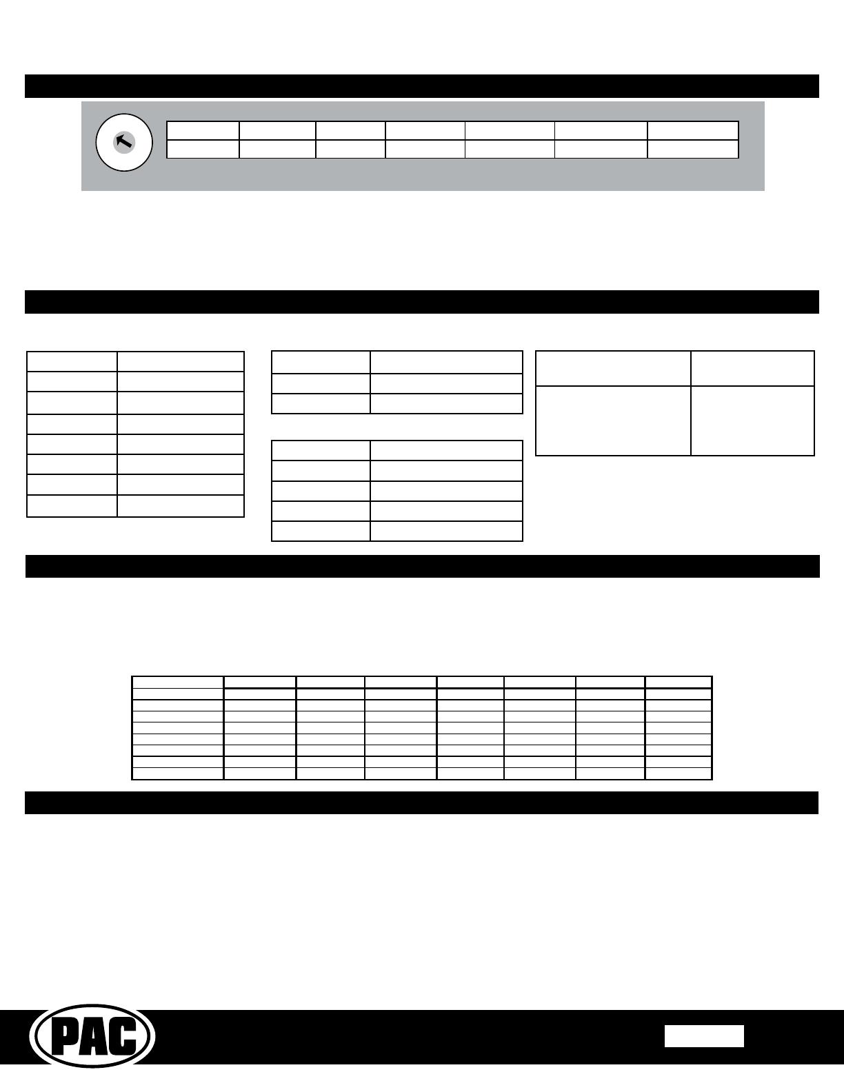
Default Steering Wheel Control Programming
Alpine JVC Kenwood Clarion Pioneer Sony Fusion
V
olume +
Volume + Volume + Volume + Volume + Volume + Volume + Volume +
V
olume -
Volume - Volume - Volume - Volume - Volume - Volume - Volume -
Seek Up
Track + Track + Track + Search + Track + Track + Track +
Seek Down
Track - Track - Track - Search - Track - Track - Track -
Band
Band / Program Band / Disc+ N / P Band Band Band N / P
1-6
Preset + Preset / Disc - Disc / FM + N / P Preset + Preset + Power
Source
Source Source Source Source Source Source Source
Mute
Mute Mute Mute Mute Mute Mute Mute
Default SWC Button Assignments
1. The radio select rotary switch on the side of the interface must be adjusted to the proper radio setting before plugging the
interface into the vehicle.
2. Make all connections as described in the chart below.
3. Connect the SWC wire or jack according to the chart below (aftermarket radio MUST support a wired remote input).
4. If you wish to reassign functions to the steering wheel controls, follow the optional programming instructions on the next page.
Conguration and Wiring of Interface
1
2
3
4
5
6
7
8
9
0
Alpine JVC Kenwood Clarion Pioneer/Other Sony Fusion
1 2 3 4 7 8 9
Other = Advent, BOYO, Dual, Lightning Audio, Rockford Fosgate, Visteon
SET RADIO SELECT SWITCH
Optional Steering Wheel Control Programming
If you wish to re-assign the SWC functions or utilize short press long press dual command functionality, the interface must be
programmed in the specic order shown on the chart on the next page. If you come across a function in the chart that your steering
wheel does not have, or you do not want to program, press and release the programming button on the side of the interface to skip
that function. The LED will ash off and on conrming that you have successfully skipped that function and are ready to proceed
to the next one.
Short Press Long Press Dual Command Functionality
This feature allows you to assign two aftermarket radio functions to each of the vehicle’s SWC buttons. It can be used with as
many of the buttons as the user likes or none at all. When this functionality is implemented, quickly pressing and releasing a SWC
button will initiate the short press command, while pressing and holding a SWC button for longer than two seconds will initiate the
long press command. Please note that no long press commands are programmed by default. If you wish to assign dual command
functionality to the SWC please follow the programming steps on the next page.
IMPORTANT! The interface comes pre-programmed for the functions listed in the chart below and does not require programming unless you
wish to re-assign the SWC functions to different buttons. The SWC can always be restored to default settings by pressing the program button
on the side of the interface once and waiting for the timeout. PLEASE NOTE: Due to the many different possible OEM SWC congurations,
some applications may need to be reprogrammed for the SWC assignments to match the button on the wheel.
Interface Connector
Vehicle Connector
SWC Connector
Vehicle Connector
Yellow Battery +12v
Black Ground
White Front Left + input
White / Black Front Left - input
Grey Front Right + input
Grey / Black Front Right - input
Green Rear Left + input
Green / Black Rear Left - input
Vehicle Connector
Purple Rear Right + input
Purple / Black Rear Right - input
Blue* Amp / Antenna Turn On
Red Accessory +12v Output
Orange / White Illumination Output (+)
Pink** Vehicle Speed Output
Purple / White** Reverse Output (+)
Light Green** Parking Brake Output (-)
* Blue wire must be connected even if the vehicle is not
equipped with an amplier. Connect to the aftermarket
radios Blue / White remote turn on wire.
** These connections are not necessary when installing
a single DIN head unit.
Complete Radio Replacement Kit with
Vehicle Information Retention for
Select 11-Bit GMLAN Vehicles
RPK4-GM2301
Pacific Accessory Corporation
Rev. 072517
Page 4
© 2017 AAMP Global. All rights reserved. PAC is a Power Brand of AAMP Global.
PAC-audio.com
Optional Steering Wheel Control Programming (cont.)
Alpine JVC Kenwood Clarion Other * Pioneer Sony Fusion
1 Volume + Volume + Volume + Volume + Volume + Volume + Volume + Volume +
2 Volume - Volume - Volume - Volume - Volume - Volume - Volume - Volume -
3 Mute Mute Mute Mute Mute Mute Mute Mute
4 Preset + Source Source Source Preset + Preset + Preset + Source
5 Preset - Track + Play Search + Preset - Preset - Preset - Track +
6 Source Track - Track + Search - Source Source Source / End Call Track -
7 Track + Band / Disc + Track - Band Track + Track + Track + Audio
8 Track - Preset / Disc - Disc / FM + Send / End Track - Track - Track - Power
9 Power Select Disc / AM - Send Band Band Band
10 Enter / Play Attenuation Answer End Answer ** Phone Menu Power / End Call
11 Band / Program Phone Receive Voice Dial VR End ** Answer Call Voice Dial / Answer / End Call
12 Receive Phone Reject On Hook PTT ** End Call
VR (Android Auto & Car Play)
Answer / End Call***
13 End Voice Dial Off Hook VR
14 VR Power Mute
15 Preset +
* Advent, Boyo, Dual, Lightning Audio, Jensen, Rockford Fosgate & Visteon ** Jensen & Advent ONLY ***
XAV-AX100 Only
Optional Programming Order
Programming
1. Turn the key to the ignition position.
2. Press and release the programming button on the side of the interface.
3. Within 7 seconds, press the button that is to be learned on the steering wheel. The LED will turn off when the button is pressed.
At this point you have two options:
A. For short press functionality: Release the button within 1.5 seconds. The LED will turn back on.
B. For long press functionality: Hold the button until the LED starts blinking. Release the button and the LED will
go back to solid.
4. If you need to program more buttons, repeat step 3 for each additional audio function on the steering wheel.
5. If you come across a function in the chart that your steering wheel does not have, or you do not want to program, press and
release the program button on the side of the interface to skip that function.
6. Once programming is completed, wait seven seconds. The LED will ash three times indicating end of programming.
7. Test the interface for proper functionality. Whenever a SWC is pressed the LED on the interface should blink. If any function
does not work, repeat the programming steps.
SWC re-calibration is necessary when the SWC operation is erratic or non-existent. This process re-calibrates the SWC values to the RPK4
interface for button function assignment. The interface must be programmed in the specic order shown in the table below. If you come across
a function in the chart that your steering wheel does not have you must press and release the program button on the side of the interface to skip
that function. The LED will ash off and on conrming that you have successfully skipped that function and are ready to proceed to the next one.
The SWC and radio command assignments can always be restored to default values by entering re-calibration mode (Steps 1-3) and not pressing
any buttons. After 7 seconds the re-calibration mode will time out and all default values will be restored.
Button Programming Order
Volume Up
Volume Down
Seek Up
Seek Down
Source
Mute
1-6
Band
1. Turn the key to the ignition position.
2. Press and hold the programming button for 7 seconds until the LED begins blinking. When the LED
begins blinking, release the programming button.
3. Within 7 seconds, press and release the button that is to be learned on the steering wheel. The LED will
turn off when the button is pressed and come back on when it is released.
4. If you need to program more buttons, repeat step 3 for each additional audio function on the steering
wheel.
5. If you come across a function in the chart that your steering wheel does not have, press and release the
program button on the side of the interface to skip that function.
6. Once programming is completed, wait 7 seconds and the LED will ash three times indicating end of
programming.
7. Test the interface for proper functionality. Whenever a SWC is pressed the LED on the interface should
blink. If any function does not work, repeat the programming steps.
8. After you have re-calibrated the SWC buttons, the default SWC button assignments will be the same as
what is listed in the chart on page 3. If you wish to re-assign button functions you must also go through
the programming process in the section above.
Steering Wheel Control Re-calibration
Complete Radio Replacement Kit with
Vehicle Information Retention for
Select 11-Bit GMLAN Vehicles
RPK4-GM2301
Pacific Accessory Corporation
Rev. 072517
Page 5
© 2017 AAMP Global. All rights reserved. PAC is a Power Brand of AAMP Global.
PAC-audio.com
Single DIN with Pocket
1. If installing this kit into a Chevrolet Cobalt, remove the shaded areas (A) at the
top of the mainframe.
2. Attach left and right mounting brackets to the kit as shown in Fig C.
3. Insert pocket into lower section of kit from the rear & lock into slots of
mounting brackets as shown in Fig. C.
4. Insert ISO mountable radio between ISO mount brackets and loosely attach
to sides of radio using screws provided with radio when possible, or screws
supplied with kit.
5. Slide the radio forward or backward for desired look and tighten the screws.
6. Attach a rear support bracket to the rear of the new radio and adjust as
necessary to support the weight of the radio (Optional).
7. Mount the PAC-LCD in the glove box or center console area using the
supplied cable.
8. Connect all necessary cables to the back of the radio and insert the dash
kit and radio combo into the dash and secure it using the (4) 9/32 screws
removed during removal of the factory radio.
A
A
Fig. C
Single DIN with LCD adapter bracket
1. Slide the LCD into the adapter bracket from the rear and secure it using the
supplied back plate and screws shown in Fig. D.
2. If installing this kit into a Chevrolet Cobalt, remove the shaded areas (A) at the
top of the mainframe shown in Fig. E.
3. Attach left and right mounting brackets to the kit as shown in Fig E.
4. Insert LCD adapter bracket into lower section of kit from the rear & lock it into
the slots of mounting brackets as shown in Fig. E.
5. Insert ISO mountable radio between ISO mount brackets and loosely attach
to sides of radio using screws provided with radio when possible, or screws
supplied with kit.
6. Slide the radio forward or backward for desired look and tighten the screws.
7. Attach a rear support bracket to the rear of the new radio and adjust as
necessary to support the weight of the radio (Optional).
8. Connect all necessary cables to the back of the radio and insert the dash
kit and radio combo into the dash and secure it using the (4) 9/32 screws
removed during removal of the factory radio.
A
A
Fig. D
Fig. E
Dash Kit Assembly
There are three congurations for installing this kit which will be covered in this section.
Double DIN
1. Remove the shaded area (A) from both the left and right mounting brackets
(Only the left bracket is shown in Fig. A to the right). Next, if installing this
kit into a Chevrolet Cobalt, remove the shaded areas (B) at the top of the
mainframe.
2. Attach left and right mounting brackets to the kit as shown in Fig B.
3. Insert ISO mountable radio between ISO mount brackets and loosely attach to
the sides of radio using screws provided with radio when possible, or screws
supplied with kit.
4. Slide the radio forward or backward for desired look and tighten the screws.
5. Attach a rear support bracket to the rear of the new radio and adjust as
necessary to support the weight of the radio (Optional).
6. Mount the PAC-LCD in the glove box or center console area using the
supplied cable length.
7. Connect all necessary cables to the back of the radio and insert the dash kit
and radio combo into the dash. Secure it using the (4) 9/32 screws removed
during removal of the factory radio.
A
B
B
Fig. B
Fig. A
Complete Radio Replacement Kit with
Vehicle Information Retention for
Select 11-Bit GMLAN Vehicles
RPK4-GM2301
Pacific Accessory Corporation
Rev. 072517
Page 6
© 2017 AAMP Global. All rights reserved. PAC is a Power Brand of AAMP Global.
PAC-audio.com
Technical Support and Product Updates (Firmware)
The RPK4-GM2301 can be updated with new rmware as it becomes available using the PAC-UP interface updater (sold separately).
Please visit www.PAC-audio.com/rmware for available updates.
Technical Support
support@PAC-audio.com
866-931-8021
Testing and Verication
1. Turn the ignition on. The LED on the interface will turn on and the +12v accessory wire will turn on.
2. Turn on the radio and check balance and fade.
3. Verify that all SWC are functioning properly.
4. Verify that the PAC-LCD is functioning properly.
5. Adjust the settings in the setup menu if necessary.
6. Turn off vehicle and remove key. RAP will be active and keep the radio on for 10 minutes or until the driver’s door is opened.
7. The LED and radio will turn off when RAP turns off, or the driver door is opened.
Setup Menu
The RPK4-GM2301 is equipped with a Setup Menu where the user can adjust the following settings:
Chimes: On or Off (Module produces warning chimes. Not needed when the vehicle produces the chimes from the dash speaker)
Chime Volume: High or Low (Changes the level of the chimes heard from our module)
Turn Signal Click: On or Off (Module makes a ticking noise whenever the turn signal is on)
Exit Menu
To access this menu, press and hold the INFO button on the PAC-LCD for 7 seconds. Once the display changes and “Chimes:
On” is displayed you can release the INFO button. To advance to the next item in the setup menu, press the MENU button or turn
the rotary dial to the right. To change any of the settings, press the ENTER button while it is displayed on the PAC-LCD. When
nished, advance to the “Exit Setup” function and press the ENTER button.
Using the PAC LCD to adjust the factory settings
With the addition of the PAC-LCD the user is able to retain the vehicle’s settings and information that would normally be lost when the factory
radio is replaced. The PAC-LCD buttons are labeled like the factory radio button, providing the user with a more factory like user experience.
Pressing the Info button will allow you to cycle through the following vehicle information: Trip A, Trip B, Fuel Range, Econ, Average Speed and
Oil Life. Pressing the Menu button or turning the rotary dial clockwise will allow you to cycle through the following vehicle settings: Oil Life Reset,
Units, Lock Horn, Unlock Horn, Lights Flash, Delay Lock, Auto Unlock, Unlock, Exterior Lights, Security and Language. The Enter button can
be used to change any of the settings while they are displayed on the screen. For additional information on the vehicle information or vehicle
settings please consult the vehicle’s owner’s manual.
EJECT
INFO
MENU
ENTER
BAND
SRCE
DSP
AUTO AUTO
TONE
ADJ
SEEK
1 2 3 4 5
6
RPT RDM
TONE
BAL FADE
CLOCK
P-TYPE
TRAF
MISC
80F
DOOR AJAR
80F
DOOR AJAR
  • Page 1 1
  • Page 2 2
  • Page 3 3
  • Page 4 4
  • Page 5 5
  • Page 6 6

PAC RPK4-GM2301 User manual

Type
User manual

PAC RPK4-GM2301 is a complete radio replacement kit with vehicle information retention for select 11-Bit GMLAN Vehicles. It features a user-friendly LCD display with onboard buttons to view and adjust vehicle information and settings. The included radio replacement interface retains factory steering wheel controls and allows programming of two radio functions to each button using short press/long press dual command functionality. It also provides data bus driven outputs like retained accessory power, illumination, vehicle speed sensor, reverse trigger, and parking brake.

Ask a question and I''ll find the answer in the document

Finding information in a document is now easier with AI