Page is loading ...

Kit Content
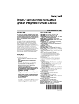
Figure 1: IOTZTB-DK006 Kit Contents
Demonstration Quick Start
This section contains the basic information necessary to start
using the IOTZTB-DK006 kit with the pre-loaded Zigbee Smart
Home Demonstration. In this demonstration, a Zigbee 3.0 network
set up is completed using a PC. Commissioning is performed via
NFC. You will then be able to control the light directly from the
switch in the network after binding.
SETUP THE CONTROL BRIDGE
1) If not already done as described in page 1, please follow steps
below:
a. The FTDI driver must be installed on you PC hard drive from
http://www.ftdichip.com/Drivers/CDM/CDM21228_Setup.zip
b. The ZGWUI.exe file must be copied on you PC hard drive. It is
available from JN-AN-1247-ZigBee-3-0-ControlBridge package
(folder AN1247\Tools\TestGUI\Source\bin\Debug).
2) Power the Zigbee Control Bridge (part #A) on FTDI USB
connector (see figure 2) to your PC using the provided USB cable
(part #6).
The green light blinks on the PN7150 NFC control shield.
Figure 2: Active control bridge-Green LED and FTDI USB port
3) On your PC, open the Zigbee Gateway User interface (ZGWUI) by
double clicking on the executable file ZGWUI.exe.
The following window appears:
a. Click on the ‘Settings’ menu: select the COM port
connected to the control bridge and click on ‘OK’.
b. Click on ’Open Port’ menu (button state changes to ‘Close
port’)
c. Click on ‘Start NWK’, you can see at the bottom left of the
ZGWUI window the raw data and bottom right the received
message log:
COMMISSION THE NETWORK VIA NFC
In this section, you will use the light node (carrier board fitted with the
lighting/sensor expansion board) and the switch node (carrier board fitted
with the generic switch expansion board).
1) Connect the light node (part #C) to the PC USB power supply (PC
or USB charger - not provided).
2) Tap the NFC antenna of the light node on the NFC
antenna of the control bridge, as shown in the Figure 3.
Part#
(fig.1)
#A
#B
#C
Device type
Zigbee
Control
Bridge
Generic
switch
node
Light
/sensor
node
1
K32W061 T10 or JN5189T
T10 module, fitted to DK6
carrier board, with embedded
NFC tag and ZigBee printed
antenna
2
DK6 carrier board with NFC
antenna
3
NFC reader board
4
Generic switch expansion
board
5
Light/Sensor expansion board
6
USB ‘A to mini B’ cable
7
K32W061 dongle
Caution: From here onwards you will use the light node.
The white LEDs on the expansion board are very bright at maximum
intensity. Do not look into them directly for an extended period of time.
Page 2
Green LED
A: ZB Control Bridge
(ZCB) with NFC Reader
shield
B: Generic switch Node
C: Light/sensor node
6
6
6
Page 4
3
4
5
2
2
2
1
1
1
FTDI USB
connector
a
b
c
Page 3

Figure 3: NFC Tap to Commission Node
a. The green LED on the NFC reader shield blinks more quickly
during commissioning and then comes back to its initial state
b. The node is then commissioned
Caution: Beware of short circuits by placing the light node battery
connectors on the NFC shield
3) To commission the generic switch node (part #B), repeat
step 1 and 2 with the generic switch node
4) The 2 nodes are present on ‘Discover Devices’ tab of the
ZGWUI:
Click on ‘Discover devices’ button, there are 2 short addresses listed
standing for the 2 nodes. Below is an example:
In case none or only one short address is present but not 2, redo the
commissioning nodes from step 2.
CONTROLLING THE LIGHT FROM THE
GENERIC SWITCH NODE
1) Bind the generic switch node to the light node as follows:
a. Light node: Press and release the USER INTERFACE button
as shown on figure 4. The 3 white LEDs will start to flash.
b. Generic switch node:
i. Press and release SW1,
ii. Hold down the USER INTERFACE button:
1. Once LED D1 starts flashing on the generic switch
node, press and release the SW2 button.
2. Release the USER INTERFACE button only when
the light node LEDs stay ON.
The nodes are now bound.
Figure 4: USER INTERFACE button on DK6 board and SW1,
SW2 buttons on generic switch expansion board
2) Experiment with the buttons SW1 to SW4 to control the white LEDs on
the Light node, as follows:
Switch
Action
Dimmable Light reaction
SW1
ON
White LEDs D1, D2 and D3 will go ON
SW2
OFF
White LEDs D1, D2 and D3 will go OFF
SW3
Dim up
White LEDs D1, D2 and D3 will light up
SW4
Dim down
White LEDs D1, D2 and D3 will be dimmed
IOTZTB-DK006
Development Kit
Getting Started
Welcome to the IOTZTB-DK006 Development Kit which allows you
to start developing Zigbee and BLE wireless networks based on
the NXP K32W061 and JN5189 family of microcontrollers. This
document describes the contents of the kit and provides ‘Quick
Start’ instructions for setting up and running the pre-loaded
Zigbee Smart Home Demonstration.
Check the Kit Content
Check the content of the development kit box using the photograph and
components list provided on page 2 of this document.
Collaterals Package Download
Please contact your local NXP account to get access to the package.
To run this demonstration:
a. The FTDI virtual COM port driver must be installed on you PC hard
drive from http://www.ftdichip.com/Drivers/CDM/CDM21228_Setup.zip
b. The ZGWUI.exe file must be copied on you PC hard drive. It is
available from JN-AN-1247-ZigBee-3-0-ControlBridge package (folder
AN1247\Tools\TestGUI\Source\bin\Debug).
Set Up and Run the Demonstration
You can now use the kit to set up and run the pre-loaded Zigbee Smart Home
Demonstration, as described in the rest of this document.
For more complete set-up instructions and information about the kit, refer to
the DK006 Development Kit User Guide (UM11393), available in the
downloaded package.
The pre-loaded demonstration software is based on a Zigbee 3.0 application.
Note: If you need to factory-reset a node, hold down the
USER INTERFACE button, then press and release the
RESET button and then release USER INTERFACE.
Page 1
JN-UG3139- v2.3
Page 5
Page 6
NFC antenna
(control bridge)
NFC antenna (Node)
USER INTERFACE button
SW1 button
SW2 button
D1 LED
/