
INSTRUCTION MANUAL
BEDIENUNGSANLEITUNG
MANUEL D’INSTRUCTIONS
VDC-D1185VP
VDC-D2185VP
COLOUR CCD camera
CCD-Farbkamera
Caméra CCD COULEUR
CCD
VDC-D1185VP (SURFACE TYPE) VDC-D2185VP (IN-CEILING TYPE)
About this manual
Before installing and using the camera, please read this manual
carefully. Be sure to keep it handy for later reference.
Über diese Bedienungsanleitung
Lesen Sie bitte vor der Montage und dem Inbetriebnehmen der
Kamera zuerst diese Bedienungsanleitung sorgfältig durch und
bewahren Sie sie zum späteren Nachschlagen auf.
A propos de ce manuel
Avant d’installer et d’utiliser la caméra, veuillez lire ce
manuel attentivement. Gardez-le à portée de main pour
toute référence ultérieure.
L5AK4/XE, L5AL4/XE GB 2003, 6, 5

Depending on the conditions of use, installation and environment,
please be sure to make the appropriate settings and adjustments.
If you need help with installation and/or settings, please consult your
dealer.
CONTENTS
PRECAUTIONS........................................................................................ 2
INSTALLATION....................................................................................... 3
SETTINGS ............................................................................................... 5
ADJUSTMENT ........................................................................................ 10
TROUBLESHOOTING ............................................................................. 11
SPECIFICATIONS.................................................................................... 12
ACCESSORIES
VDC-D1185VP
• Hexagonal Wrench (Big)........................................................... 1 pc.
• Hexagonal Wrench (Small) ....................................................... 1 pc.
• Cushioning sheet...................................................................... 1 pc.
• Ferrite core ............................................................................... 2 pc.
VDC-D2185VP
• Hexagonal Wrench (Big)........................................................... 1 pc.
• Cushioning sheet...................................................................... 1 pc.
• Ferrite core ............................................................................... 2 pc.
FEATURES
• The optical filter is switched automatically to colour image or black
and white image according to the subject brightness.
• Built-in interline transfer method 1/4" CCD, approx. 470,000
picture elements.
• Equipped with a DSP (Digital Signal Processor).
• Horizontal resolution, more than 520 TV lines.
• High sensitivity, minimum required illumination is 0.06 lux (F1.4
B/W mode).
• Two types of backlight compensation functions (multi-spot
photometry and centre-focus photometry).
• Dual power supply 12 – 15 V DC or 24 V AC.
L5AK4/XE, L5AL4/XE GB 2003, 6, 5
English
1
PRECAUTIONS
In case of malfunction
Do not use the camera if smoke or a strange odour comes from the
unit, or if it seems not to function correctly. Disconnect the power
supply immediately, and consult your dealer (or a Sanyo Authorized
Service Centre).
Do not open or modify
Do not open the cabinet, as it may be dangerous and cause damage
to the unit. For internal settings and repairs, consult your dealer (or a
Sanyo Authorized Service Centre).
Do not put objects inside the unit
Make sure that no metal objects or flammable substances get inside
the camera. If used with a foreign object inside, it could cause a fire,
short-circuit or damage.
If water or a liquid gets inside the camera, disconnect the power
supply immediately, and consult your dealer (or a Sanyo Authorized
Service Centre). Be careful to protect the camera from sea water, etc.
Be careful when handling the unit
To prevent damage, do not drop the camera or subject it to strong
shock or vibration.
Install away from electric or magnetic fields
If installed close to a TV, radio transmitter, magnet, electric motor,
transformer, or audio speakers the magnetic field they generate will
distort the image.
Protect from humidity
To prevent damage to the camera, do not install it where there is
greasy smoke or steam or where the dampness may get too high.
Protect from high temperatures
Do not install close to stoves, or other heat generating devices, such
as spotlights, etc., or where it could be subject to direct sunlight, as
that could cause deformation, discoloration or other damage.
Be careful when installing close to the ceiling, in a kitchen or boiler
room, as the temperature may rise to high levels.
Install where the temperature range will stay between –10°C and
50°C. (no condensation)
Cleaning
Dirt can be removed from the housing by wiping it with a soft cloth.
To remove stains, wipe with a soft cloth moistened with a soft
detergent solution and wrung dry, then wipe dry with a dry soft cloth.
Do not use benzine, thinners or other chemical products on the
housing, as they may cause deformation and paint peeling. Before
using a chemical cloth, make sure to read all accompanying
instructions. Make sure that no plastic or rubber material comes into
contact with the housing for a long period of time, as that may cause
damage or paint peeling.
Mounting Surface
The mounting surface material must be strong enough to secure the
camera. Plaster- board without a backing plate is not recommended.
ENGLISH
L5AK4/XE, L5AL4/XE GB 2003, 6, 5
2
English
INSTALLATION
Note:
When setting up this camera, make sure that it is installed securely. If it
is not installed correctly, it may fall down. In addition, do not touch the
camera in places except where settings and adjustments are necessary.
Coaxial cable type and maximum length
•
Cable type RG-59U (3C-2V), 250 m maximum.
•
Cable type RG-6U (5C-2V), 500 m maximum.
•
Cable type RG-11U (7C-2V), 600 m maximum.
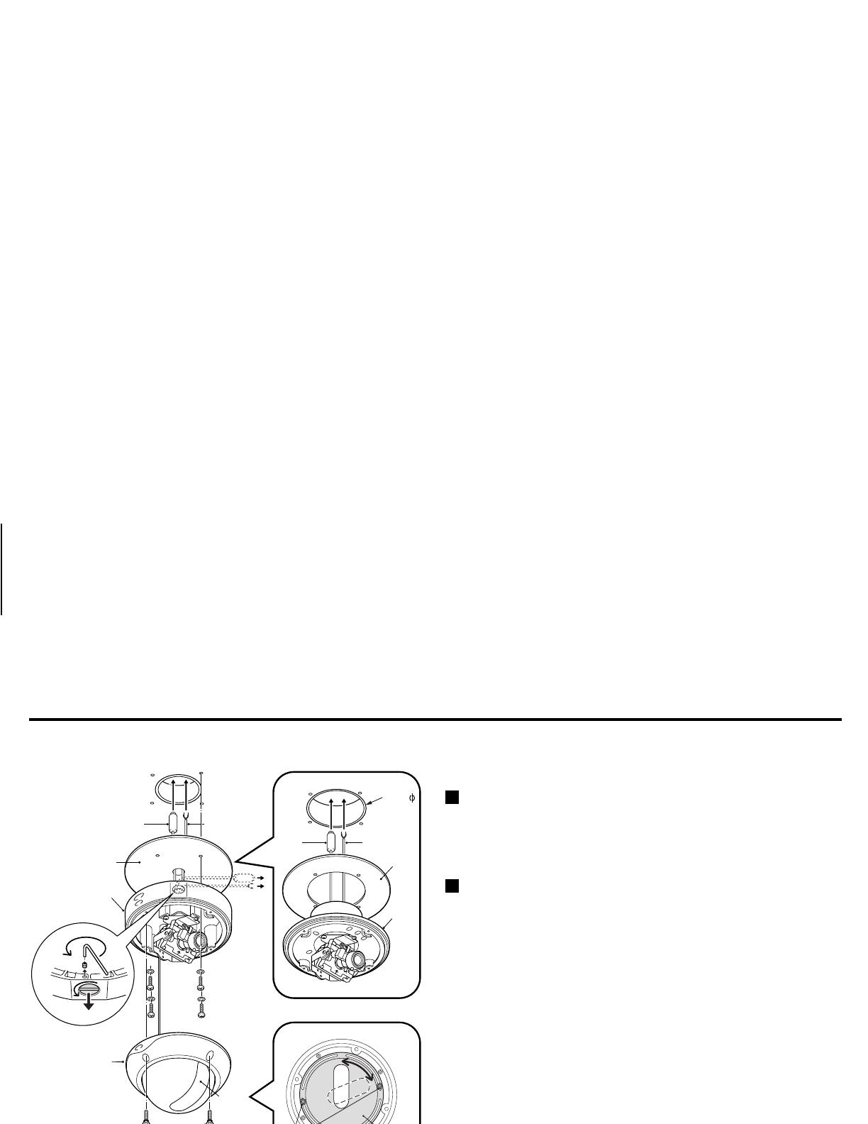
Installing the Model VDC-D1185VP
1
Use the supplied hexagonal wrench to remove the four fixing
screws
(B)
of dome cover
(A)
.
2
Make screw holes and a cable hole in the cushioning sheet
(D)
that attaches to the back of the camera unit
(C)
.
3
Attach the cushioning sheet (double-sided tape) to the back of the
camera unit.
4
Align the camera unit with the surface of the ceiling, make marks
on the ceiling in the places where the screw holes are to be drilled,
and then drill the four holes.
5
Cut a hole in the ceiling for routing the cables.
Note:
When routing the cables in the ceiling, use the accessory hexagonal
wrench (small) to loosen the cable cover fixing screw (E) at the rear
of the unit, and then remove the cable cover screw (F).
The following step differs only when installing the Model
VDC-D2185VP
Make a cable hole with a diameter of 73 mm.
73mm
(A)
(B)
(H)
(G)
(K)
(D)
(C)
(Model VDC-D1185VP)
(Model VDC-D2185VP)
(J)
(I)
(H)
(G)
(C)
(D)
(E)
(F)
L5AK4/XE, L5AL4/XE GB 2003, 6, 5
English
3
INSTALLATION
6
Pass the power cable/day-night cable
(G)
and video cable
(H)
from the camera unit through the cable hole in the ceiling.
(Power cable/day-night cable)
7
Align the four screw holes in the camera unit
(C)
with the screw
holes in the ceiling, and then secure the camera in place by
tightening the screws.
8
Carry out the settings and adjustments for the camera.
Refer to p. 5 for camera settings and adjustments, and to p. 10
for lens adjustments.
9
If the dome liner is secured in place, loosen the screw
(I)
.
Adjust the dome liner
(J)
so that the dome camera’s lens is visible
from the camera window
(K)
, and then use a hexagon wrench to
fix the dome cover.
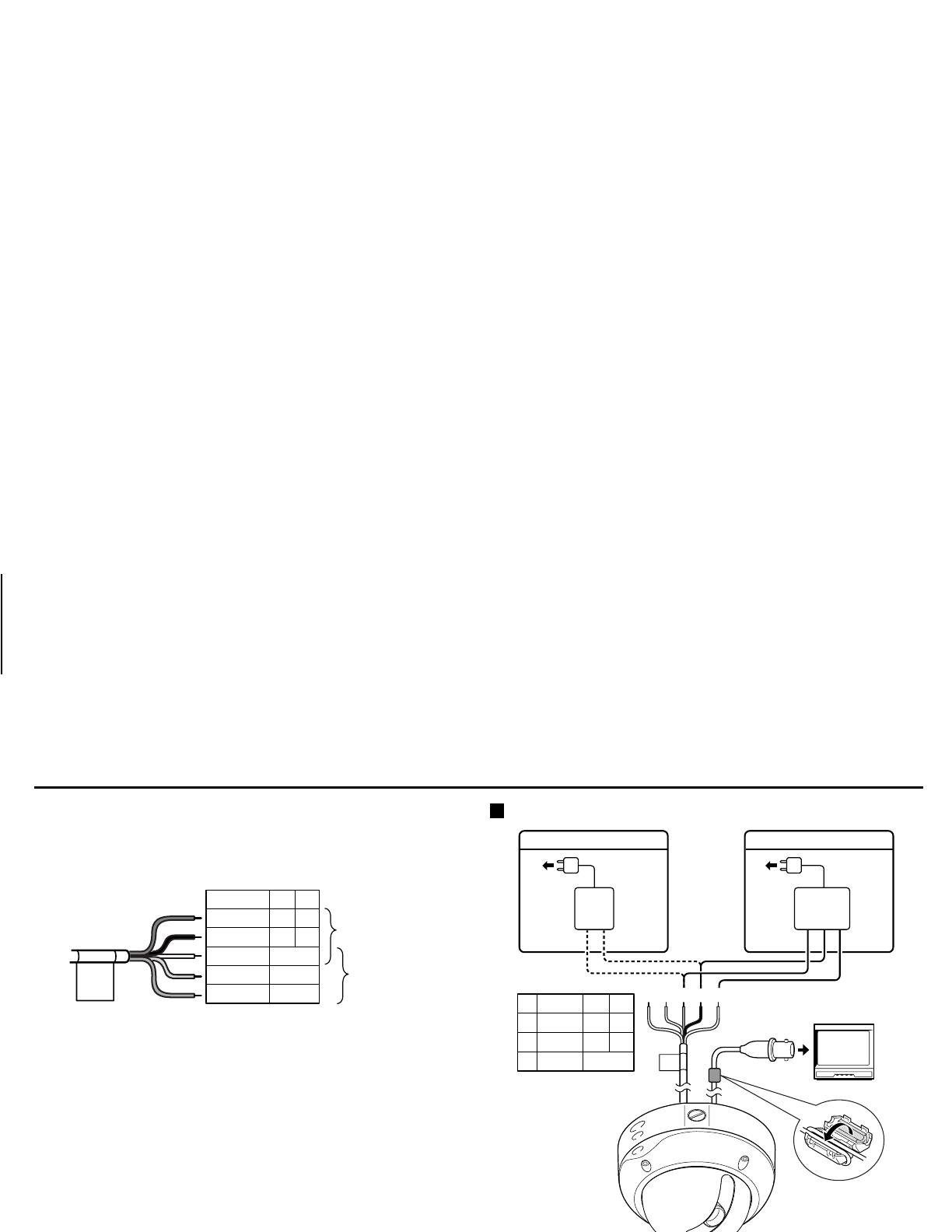
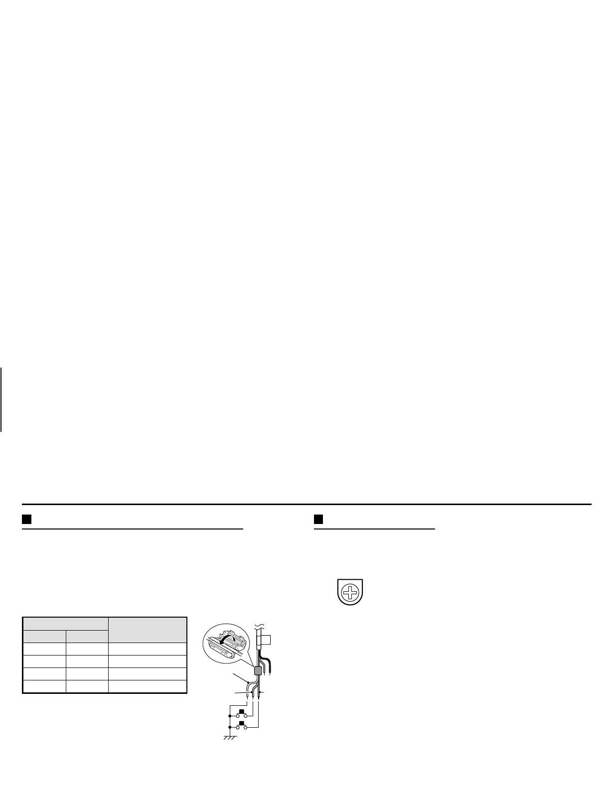
Connections
Note:
When connecting the video cable of this unit to a TV monitor,
the accessory ferrite core (two winds) must be installed to the
video cable in order to prevent electromagnetic interference
with the other connected devices.
RED
Cable
BLACK
WHITE
YELLOW
PURPLE
GND
COLOR
B/W
+~
~
–
DC12 AC24
Power cable
Day/night
cable
AC 24 V connection
DC 12 V connection
1
1
RED
Cable
BLACK
WHITE
GND
2
3
23
+
+~
~
–
–
~~
GND
DC12 AC24
L5AK4/XE, L5AL4/XE GB 2003, 6, 5
4
English

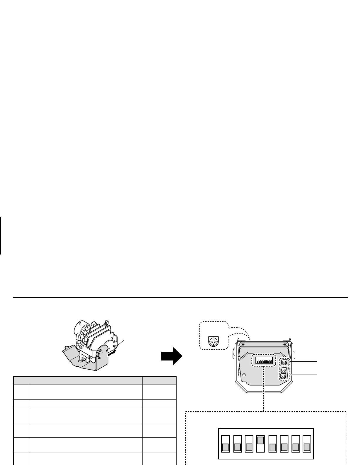
SETTINGS
When changing the settings and adjustments for this camera, loosen the camera unit screw
(A)
and remove the lens unit in the direction of the
arrow. When changing the DIP switch settings, take care when making the settings and adjustments because power is still being supplied to the
camera.
Control name Position
1
Colour and Black/White level switch (C/B)
(Normal: LOW/High sensitivity: HI)
LOW
23
High speed electronic shutter setting (ES)
1/50 sec.
4
Aperture compensation setting (AP)
(Sharp: SHRP/Normal: NORM)
SHRP
5
Backlight compensation setting (BL-M)
(ON (MULT)/OFF)
OFF
6
Backlight compensation setting (BL-C)
(ON (CENT)/OFF)
OFF
7
White balance switch (WB) and colour
(R or B) adjustment volume
ATW
8
Synchronization setting (SYNC)(LL/INT)
INT
9
Line phase adjustment (PHASE)
adjustable
F
Lens iris level adjustment
adjustable
(A)
1 2 3 4 5 6 7 8
HI
C/B ES AP BL-M BL-C WB SYNC
1 2 SHRP ON ON MANU LL
LOW OFF OFF NORM OFF OFF ATW INT
F
VR121
7
1
ON
234 5678
9
The illustration shows the factory default settings for the switches in the camera setup section.
L5AK4/XE, L5AL4/XE GB 2003, 6, 5
English
5

SETTINGS
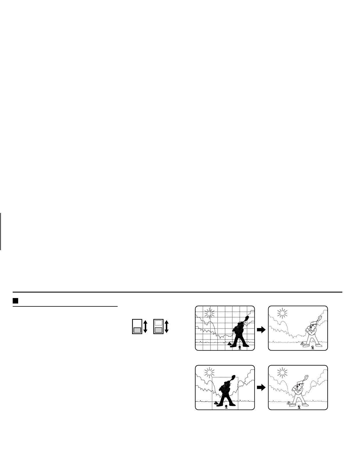
C •
••
• B/W (colour/black and white) switch setting
This switch lets you select the timing of the automatic switching of
the optical filter to colour image or black and white image, according
to the subject brightness. The default setting is down (
LOW
). Set the
switch according to the brightness.
(Fig. 1)
H:
for a brighter setting than
LOW
L:
Standard setting
Notes:
• After the power has been turned off, switching will restart from
colour, when the power is restored.
• A sound may be heard when the colour image or black and white
image is switched. Also, the image will be distorted as shown in
Fig. 1
, this is normal and does not indicate a problem.
• When using infrared lighting, if there is a strong reflection on the
subject, the optical filter may switch from black and white to
colour mode. Use only enough infrared lighting so that the mode
is not switched.
• The focus setting may be different in black and white mode and
colour mode. Please check the focus setting in both modes.
High speed electronic shutter setting
Normally, the speed setting switches for the high speed electronic
shutter are all set to the down (
OFF
) position. This sets the electronic
shutter (
ES 1, 2
) speed to 1/50 sec. The switches can be set as
indicated in table
A
to select one of the
4
speeds available.
CAUTION:
Using the high speed electronic shutter indoors with low lighting, will
give darker pictures. In such a case, add some lights to make sure the
lighting is sufficient. If the lighting is very bright, pay attention to the
light angle in order to avoid or minimize the smear phenomenon
effect.
Table A (switch 2 ~ 3)
1
1/50
2
1/120
3
1/1000
4
1/2000
(Unit: sec.)
Aperture
If you would like to emphasize the contours of the
object, set the switch
4
(
AP
) to the up (
SHRP
) position.
1
23 23 23 23
4
L5AK4/XE, L5AL4/XE GB 2003, 6, 5
6
English
SETTINGS
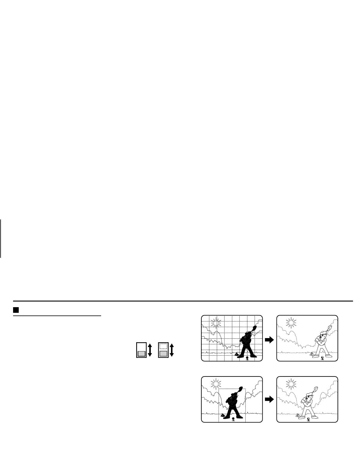
Backlight compensation setting
This camera has two different backlight
compensation functions: Normally backlight
compensation switch
5
(
BL-M
) and
6
(
BL-C
)
are set to the down (
OFF
) position. Change
the backlight compensation switch settings
depending on the conditions.
•
BL-M mode:
(Multi-spot)
Use this position when applying backlight
compensation to the whole of the screen.
•
BL-C mode:
(Centre-focus)
Use this position when applying backlight
compensation to only the central portion of the
screen.
Note:
• If switches
5
and
6
are set to the up (
ON
) position at the same
time, the
BL-M
setting will have priority.
• When
BL-M
mode is set, scenes with no backlighting may appear
extremely dark and the object may appear over-exposed. If this
happens, set to
BL-C
mode.
5 6
(BL-M mode: 64 sections)
(BL-C mode)
L5AK4/XE, L5AL4/XE GB 2003, 6, 5
English
7

SETTINGS
White balance adjustment
Normally the switch
7
(
WB
) is set to the down (
ATW
: auto white
balance) position and the white balance is adjusted automatically. If a
manual white balance adjustment is necessary, follow the steps below.
Set the switch
7
(
WB
) to the up (
MANU
: manual) position, then
adjust the colour.
• Turn
R
(VR302) to set the red ratio and/or
B
(VR303) to set the
blue ratio.
Synchronization settings
The default setting is internal synchronization (
INT
). You can change
the power supply synchronization by moving switch
8
to the up (
LL
)
position. Refer to “
Line phase adjustment
” for details.
Line phase adjustment
When using a camera switcher to connect 2 cameras or more to one
monitor, there may be a vertical roll of the images when switched. In
such a case, set as described below.
1
Set the switch
8
(
SYNC
) to the up (
LL
) position.
2
Switch the display on the monitor from camera 1 to camera 2.
Adjust the
PHASE
volume on camera 2 until the vertical roll of the
image stops.
If more than two cameras are used, please repeat this procedure
for all the cameras.
CAUTION:
If the vertical roll cannot be corrected by setting the
PHASE
volume
on camera 2, try setting the
PHASE
volume on camera 1. If it still
cannot be corrected, please check that the polarity of the power
cords of all connected devices is correct.
7
VR302VR303
B
R
WB
8
VR322
PHASE
L5AK4/XE, L5AL4/XE GB 2003, 6, 5
8
English
SETTINGS
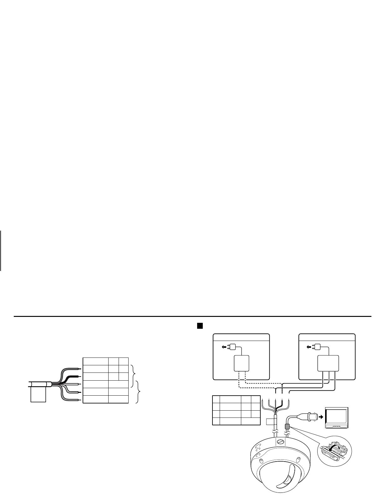
Manual colour/black and white setting
Connect each cable as indicated below, to set the image to black and
white or colour as desired.
•
Colour image setting
Connect the
Colour
(yellow) and the
White
(ground) cables.
•
Black and white setting
Connect the
B/W
(purple) and the
White
(ground) cables.
Day/night cable
Image
Colour B/W
OFF OFF Auto
OFF ON Black and white
ON OFF colour
ON ON Auto
ON
: Close
OFF
: Open
Notes:
•
The maximum length of cable for CONTROL terminal is 600 m (AWG 24).
•
During optical filter switching, even if the manual switching operation is
done, you cannot determine if the image is black and white or colour.
Manual switching will have to be done one more time.
•
When using a day/night setting, the accessory ferrite core (two winds) must
be installed to the day/night cable in order to prevent electromagnetic
interference with the other connected devices.
Lens iris adjustment
You will need to set the
LEVEL
(VR121) volume when shooting in the
conditions described below.
Counterclockwise:
To decrease the contrast
Clockwise:
To increase the contrast
• If shooting simultaneously in a dark room and through a bright
window.
• If the subject background is extremely bright or dark.
• If the brightness of the picture on the monitor is not correct.
GND
(White)
Colour
(Yellow)
B/W
(Purple)
VR121
L5AK4/XE, L5AL4/XE GB 2003, 6, 5
English
9

ADJUSTMENT
Adjusting the lens
Once the camera has been installed, adjust the lens section.
1
Tighten the pan adjustment screw.
Model: VDC-D2185VP
Loosen the pan adjustment screw, adjust the panning position of
the lens and then re-tighten the screw.
Model: VDC-D1185VP
Remove the lens unit
A
from the pan chassis, loosen the pan
adjustment screw
B
, turn the chassis to adjust the panning
position to a position where one of the three screw holes
C
is
visible, and then re tighten the screw.
2
Loosen the tilt adjustment screw, adjust the tilting position of the
lens and then re-tighten the screw.
3
Loosen the zoom lever screw, turn the zoom lever
counterclockwise to determine the zoom position while viewing
the camera images on the monitor, and then re-tighten the screw.
4
Loosen the focus lever screw, turn the focus lever
counterclockwise to determine the focus position while viewing
the camera images on the monitor, and then re-tighten the screw.
Note:
Be careful not to touch the lens section when changing the
angle of the camera.
3
4
1
1
2
A
B
C
C
C
Model: VDC-D2185VA
Model: VDC-D1185VA
L5AK4/XE, L5AL4/XE GB 2003, 6, 5
10
English
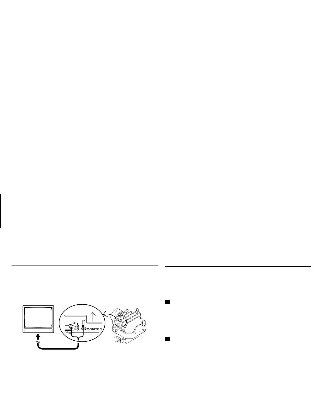
ADJUSTMENT
MONITOR output pin
When setting up the camera, connect a monitor to this video output
pin and to the GND screw using alligator clip cables, then using the
image displayed on the monitor, set the surveillance angle and range,
the lens focus, etc.
TROUBLESHOOTING
Before taking the camera for repairs, please check below to make
sure that the camera is used correctly. If it still does not perform
correctly, please consult your dealer or a Sanyo Authorized Service
Centre.
No picture on the monitor screen
• Is the power turned on to all connected devices? Is the voltage
correct?
• Are all the signal connecting cables correctly connected?
• Is the lighting sufficient?
The picture is not clear
• Is the monitor correctly adjusted?
• Is the lens focus correctly adjusted?
• Are the lens surfaces clean?
If there is dust or finger prints on the lens, the image quality will
deteriorate. To clean the lens use a soft cloth or a commercially
available lens cleaning set.
SERVICE
This camera is a precision instruments and if treated with care, will
provide years of satisfactory performance. However, in the event of a
problem, the owner is advised not to attempt to make repairs or open
the cabinet. Servicing should always be referred to your dealer or
Sanyo Authorized Service Centre.
L5AK4/XE, L5AL4/XE GB 2003, 6, 5
English
11
SPECIFICATIONS
Scanning system :
PAL standard
(625 TV lines, 25 frames/sec.)
Interlace :
PLL 2:1 interlace
Image device :
1/4 inch solid state image device CCD
Picture elements :
795 (H) x 596 (V)
Effective picture elements :
752 (H) x 582 (V)
Synchronizing system :
Internal sync, Line lock
Resolution :
520 TV lines horizontally, 400 TV lines
vertically
Video output level :
1.0 Vp-p/75 ohms, composite
Video S/N ratio :
More than 48 dB
Minimum required
illumination
(incandescent lighting)
:
Approx. 0.06 lux with a F 1.4 lens
(B/W mode),
Approx. 1.2 lux with a F 1.4 lens
(colour mode)
Power and Day/night
cable
:
Manual colour/black and white setting
Backlight compensation :
Manual ON (Multi-spot photometry,
Centre-focus photometry)/OFF
switching
(Active when using an auto-iris lens)
Electronic shutter :
4 speeds, selectable by switches:
(1/50, 1/120, 1/1000, 1/2000 sec.)
White balance :
ATW/Manual switching
Pan/Tilt adjustment :
Manual Pan: ±180 degree,
Tilt: 115 degree
Lens :
f=2.8 – 5.8 mm, F1.4 – F1.8
Environmental conditions :
Temperature: –10° C ~ +50°C
Humidity: less than 90% (no
condensation)
Power supply :
24 V AC, 50 Hz and 12 – 15 V DC
Power consumption :
2.9 W
Weight :
VDC-D1185VP: Approx. 1,350 g
VDC-D2185VP: Approx. 1,015 g
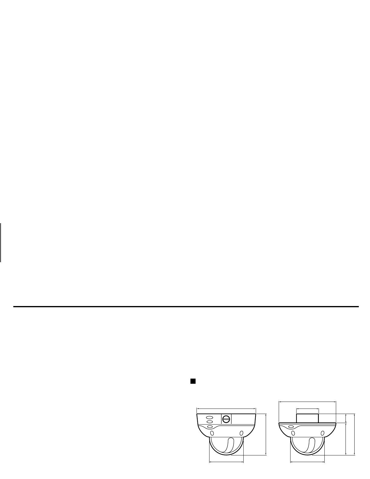
Dimensions (mm)
Features and specifications are subject to change without prior
notice or obligations.
100.5
114.8
162.0
162.0
73.0
100.5
29
85.8
114.8
VDC-D1185VP VDC-D2185VP
L5AK4/XE, L5AL4/XE GB 2003, 6, 5
12
English

Entsprechend der Betriebsbedingungen, der Montage und den
Umgebungs- bedingungen müssen Sie kontrollieren, ob die
entsprechenden Einstellungen richtig gemacht wurden. Für Ratschläge
zur Montage und für die Einstellungen können Sie sich an Ihren
Händler wenden.
INHALT
VORSICHTSMASSNAHMEN .................................................................. 2
MONTAGE.............................................................................................. 3
GRUNDEINSTELLUNGEN....................................................................... 5
EINSTELLUNGEN.................................................................................... 10
FEHLERSUCHE........................................................................................ 11
TECHNISCHE DATEN ............................................................................. 12
ZUBEHÖR
VDC-D1185VP
• Sechskantschlüssel (groß)............................................................... 1
• Sechskantschlüssel (klein) ............................................................... 1
• Unterlage ....................................................................................... 1
• Ferritmuffe ..................................................................................... 2
VDC-D2185VP
• Sechskantschlüssel (groß)............................................................... 1
• Unterlage ....................................................................................... 1
• Ferritmuffe ..................................................................................... 2
BESONDERHEITEN
• Der optische Filter wird automatisch entsprechend der Helligkeit
des Aufnahmegegenstandes auf Farbe oder Schwarzweiß
umgeschaltet.
• 1/4"-CCD mit eingebauter Interline-Übertragung, ca. 470.000
Bildelemente.
• Mit DSP (Digital Signal Processor) ausgerüstet.
• Horizontale Bildauflösung, mehr als 520 Zeilen.
• Hohe Empfindlichkeit, die minimale Beleuchtung beträgt 0,06 lx
(F1,4, Schwarzweißbetriebsart).
• Zwei Arten von Gegenlichtkompensation (Mehrzonenlichtmessung
und mittenbetonte Lichtmessung).
• Zweifache Stromversorgung 12 – 15 V Gleichstrom oder 24 V
Wechselstrom
L5AK4/XE, L5AL4/XE D 2003, 6, 5
Deutsch
1

VORSICHTSMASSNAHMEN
Im Fall von Störungen
Beim Auftreten eines ungewöhnlichen Geruchs, einer Rauchentwicklung oder
einer Funktionsstörung darf die Kamera nicht verwendet werden. Unterbrechen
Sie unverzüglich die Stromversorgung und wenden Sie sich an Ihren Händler
(oder an ein autorisiertes Sanyo-Kundendienstzentrum).
Die Kamera darf nicht geöffnet und es dürfen keine
Änderungen vorgenommen werden
Das Kameragehäuse darf nicht geöffnet werden, weil ein elektrischer Schlag
ausgelöst und die Kamera beschädigt werden kann. Für Einstellungen und
Reparaturen müssen Sie sich an Ihren Händler oder an eine autorisierte
SANYO-Kundendienststelle wenden.
Es dürfen keine Fremdkörper in die Kamera gelangen
Es dürfen keine metallenen Gegenstände oder brennbare Substanzen in das
Innere der Kamera gelangen, weil dadurch ein Feuer, ein Kurzschluß oder
Beschädigungen verursacht werden können.
Falls Wasser oder eine Flüssigkeit in die Kamera eingedrungen sind,
unterbrechen Sie unverzüglich die Stromversorgung und wenden Sie sich an
Ihren Händler (oder an ein autorisiertes Sanyo-Kundendienstzentrum). Seien Sie
vorsichtig, dass die Kamera keinem Meereswasser usw. ausgesetzt wird.
Behandeln Sie die Kamera mit Sorgfalt
Um Beschädigungen zu verhüten, darf die Kamera nicht fallen gelassen oder
starken Stößen oder Vibrationen ausgesetzt werden.
Installieren Sie die Kamera nicht in der Nähe von starken
elektrischen oder magnetischen Feldern
Durch die Installation der Kamera in der Nähe eines Fernsehgerätes,
Radiosenders, Magneten, Elektromotors, Transformators oder von
Lautsprechern kann das Bild wegen dem vorhandenen Magnetfeld verzerrt
werden.
Vor Feuchtigkeit schützen
Zum Schutz vor Beschädigung darf die Kamera nicht an Orten installiert werden,
an denen sie öligem Rauch, Dampf oder hoher Feuchtigkeit ausgesetzt ist.
Die Kamera darf keinen hohen Temperaturen ausgesetzt
werden
Installieren Sie die Kamera nicht in der Nähe eines Ofens oder anderer
Wärmequellen, wie einer Spotleuchte usw. oder an Orten mit direktem
Sonnenlichteinfall, weil dadurch Deformationen, Verfärbungen und andere
Beschädigungen verursacht werden können.
Sind Sie vorsichtig, wenn Sie die Kamera an einer Decke, in einer Küche oder in
einem Kesselraum installieren, weil die Temperatur stark ansteigen kann.
Die Umgebungstemperatur sollte zwischen –10°C und 50°C betragen. (keine
Kondensatbildung)
Reinigen
Entfernen Sie Staub auf dem Gehäuse mit einem weichen Tuch. Zum Entfernen
von Flecken können Sie ein mit einer Reinigungsmittellösung angefeuchtetes
Tuch verwenden. Wischen Sie danach die Stelle mit einem trockenen weichen
Tuch trocken.
Verwenden Sie zum Reinigen kein Benzin, Farbverdünner oder andere
Lösungsmittel, weil das Gehäuse deformiert und die Farbe sich lösen kann.
Wenn Sie ein speziell behandeltes Reinigungstuch verwenden, müssen Sie die
Anweisungen genau beachten. Das Gehäuse darf nicht für längere Zeit mit
Gummi- oder Kunststoffteilen in Berührung kommen, weil es beschädigt werden
und sich die Farbe ablösen kann.
Montagefläche
Die Montagefläche muss eine ausreichende Tragfähigkeit für die Kamera
aufweisen. Eine Befestigung an einer Gipsplatte ohne Stützplatte auf der
Rückseite wird nicht empfohlen.
DEUTSCH
L5AK4/XE, L5AL4/XE D 2003, 6, 5
2
Deutsch

MONTAGE
Hinweis:
Bei der Montage muss die Kamera auf richtige Befestigung
kontrolliert werden. Bei einer falschen Montage kann die Kamera
herunter fallen. Berühren Sie außerdem die Kamera nur an den
Stellen die für die Installation und die Einstellungen notwendig sind.
Koaxialkabel und maximale Länge
•
Kabeltyp RG-59U (3C-2V), max. 250 m
•
Kabeltyp RG-6U (5C-2V), max. 500 m
•
Kabeltyp RG-11U (7C-2V), max. 600 m
Installation des Modells VDC-D1185VP
1
Entfernen Sie die vier Schrauben (B) der Domabdeckung (A) mit dem
mitgelieferten Sechskantschlüssel.
2
Machen Sie die entsprechenden Löcher für die Schrauben und die Kabel in
die Unterlage (D), die an der Rückseite der Kamera (C) angebracht wird.
3
Bringen Sie die Unterlage (doppelseitiges Klebeband) an der Rückseite der
Kamera an.
4
Richten Sie die Kamera auf die Decke aus und markieren Sie die vier Stellen
an der Decke für die Löcher. Bohren Sie danach die Löcher in die Decke.
5
Schneiden Sie ein Loch in die Decke zur Verlegung der Kabel.
Hinweis:
Verwenden Sie für die Verlegung der Kabel in der Decke den
Sechskantschlüssel (klein) aus dem Zubehör zum Lösen der
Kabelabdeckungsschraube (E) auf der Rückseite und nehmen
Sie die Kabelabdeckung (F) ab.
Der folgende Schritt ist nur für die Installation des Modells
VDC-D2185VP verschieden.
Machen Sie ein Kabelloch mit einem Durchmesser von 73 mm.
73mm
(A)
(B)
(H)
(G)
(K)
(D)
(C)
(J)
(I)
(H)
(G)
(C)
(D)
(E)
(F)
(Modell VDC-D1185VP) (Modell VDC-D2185VP)
L5AK4/XE, L5AL4/XE D 2003, 6, 5
Deutsch
3
MONTAGE
6
Führen Sie das Netzkabel, das Tag-Nacht-Kabel
(G)
und das
Videokabel
(H)
von der Kamera durch das Kabelloch in der Decke.
(Netzkabel, Tag-Nacht-Kabel)
7
Richten Sie die vier Schraubenlöcher der Kamera
(C)
auf die
Schraubenlöcher in der Decke aus und ziehen Sie die Schrauben
zum Befestigen der Kamera fest.
8
Nehmen sie die Einstellungen für die Kamera vor.
Für die Kameraeinstellungen wird auf die Seite 5 und für die
Objektiveinstellungen auf die Seite 10 verwiesen.
9
Lösen Sie nach der Befestigung der Domabdeckung die Schrauben
(I)
.
Stellen Sie die Domabdeckung
(J)
so ein, dass das Kameraobjektiv
vom Kamerafenster
(K)
her sichtbar ist und befestigen Sie die
Domabdeckung mit dem Sechskantschlüssel.
Anschlüsse
Hinweis:
Für den Anschluss des Videokabels dieses Gerätes an einem
TV-Monitor muss die Ferritmuffe aus dem Zubehör am
Videokabel (zwei Kabelwindungen) zur Vermeidung
elektromagnetischer Störung von anderen Geräten
angebracht werden.
ROT
Kabel
SCHWARZ
WEISS
GELB
VIOLETT
MASSE
FARBE
S/W
+~
~
–
DC12 AC24
Netzkabel
Tag-Nacht-
Kabel
123
+
–
~~
GND
1
2
3
+~
~
–
DC12 AC24
ROT
Kabel
SCHWARZ
WEISS
MASSE
24 V Wechselstromanschluss12 V Gleichstromanschluss
L5AK4/XE, L5AL4/XE D 2003, 6, 5
4
Deutsch
GRUNDEINSTELLUNGEN
Um Einstellungen zu ändern, lösen Sie die Kameraschraube
(A)
und entfernen Sie das Objektiv in Pfeilrichtung. Bei der Änderung der
DIP-Schaltereinstellungen müssen Sie vorsichtig sein, weil die Stromversorgung der Kamera nicht unterbrochen ist.
Gegenstand Position
1
Schalter für Farbe und Schwarzweiß (C/B)
(Normal: LOW/Hohe Empfindlichkeit: HI)
LOW
23
Einstellen einer kurzen Verschlußzeit (ES)
1/50 s
4
Blendenöffnungskompensationsschalter
(AP) (Scharf: SHRP/Normal: NORM)
SHRP
5
Gegenlichtkompensationsschalter (BL-M)
(ON (MULT)/OFF)
OFF
6
Gegenlichtkompensationsschalter (BL-C)
(ON (CENT)/OFF)
OFF
7
Weißabgleich- (WB) und
Farbeinstellungsschalter (R oder B)
ATW
8
Synchronisation (SYNC)(LL/INT)
INT
9
Zeilenphaseneinstellung (PHASE)
einstellbar
F
Blendenpegel
einstellbar
(A)
1 2 3 4 5 6 7 8
HI
C/B ES AP BL-M BL-C WB SYNC
1 2 SHRP ON ON MANU LL
LOW OFF OFF NORM OFF OFF ATW INT
F
VR121
7
1
ON
234 5678
9
In der Abbildung werden die Standard-Schaltereinstellungen der
Kamera-Einstellelemente bei der Auslieferung gezeigt.
L5AK4/XE, L5AL4/XE D 2003, 6, 5
Deutsch
5

GRUNDEINSTELLUNGEN
Einstellung des C •
••
• B/W-Schalters
(Farbe/Schwarzweiß)
Mit diesem Schalter kann der Zeitpunkt der automatischen
Umschaltung des optischen Filter auf Farbe oder Schwarzweiß
entsprechend der Umgebungshelligkeit eingestellt werden. Die
Voreinstellung ist die untere Position. Stellen Sie den Schalter nach der
Helligkeit ein.
(Abb. 1)
H:
hellere Einstellung als
LOW
L:
Standardeinstellung
Hinweise:
•
Nach dem Ausschalten wird beim Wiedereinschalten auf Farbe
umgeschaltet.
•
Beim Umschalten zwischen Farbe und Schwarzweiß ertönt ein akustisches
Signal. Das Bild wird verzerrt, wie in
Abb. 1
gezeigt. Das ist normal und
bedeutet nicht, daß eine Störung vorhanden ist.
•
Falls bei Infrarotbeleuchtung eine starke Reflexion auftritt, kann der optische
Filter von Schwarzweiß auf Farbe umschalten. Vermindern Sie in diesem Fall
die Infrarotbeleuchtung, so daß keine Umschaltung auftritt.
•
Die Scharfeinstellung kann für Schwarzweiß und Farbe etwas verschieden
sein. Kontrollieren Sie deshalb die Scharfeinstellung in beiden Betriebsarten.
Einstellen einer kurzen Verschlußzeit
Normalerweise sind die Verschlusszeitschalter für den elektronischen
Verschluss alle nach unten in die Position (
OFF
) gestellt. Damit ist die
Verschlusszeit des elektronischen Verschlusses (ES 1, 2) auf 1/50 s
eingestellt. Die Schalter können wie in der Tabelle
A
gezeigt
eingestellt werden, um eine der
4
verschiedenen Verschlusszeiten
einzustellen.
VORSICHT:
Die Verwendung einer kurzen Verschlußzeit für Innenaufnahmen mit
schwacher Beleuchtung ergibt ein dunkleres Bild. Sorgen Sie in diesem
Fall für eine zusätzliche Beleuchtung. Bei sehr heller Beleuchtung
müssen Sie auf den Lichteinfallswinkel achten, um den Schmiereffekt
zu eliminieren oder zumindest auf ein Minimum zu reduzieren.
Tabelle A (Schalter 2 ~ 3)
1
1/50
2
1/120
3
1/1000
4
1/2000
(Einheit: s)
Blendenöffnung
Um die Konturen des Aufnahmegegenstandes
hervorzuheben, können Sie den Schalter
4
(
AP
) nach
oben in die Position
SHRP
stellen.
1
23 23 23 23
4
L5AK4/XE, L5AL4/XE D 2003, 6, 5
6
Deutsch
GRUNDEINSTELLUNGEN
Gegenlichtkompensation
Diese Kamera besitzt zwei verschiedene
Gegenlichtkompensationsfunktionen:
Normalerweise werden die
Gegenlichtkompensationsschalter
5
(
BL-M
)
und
6
(
BL-C
) in die Position (
OFF
) gestellt. Je
nach den Bedingungen können Sie die
Gegenlichtkompensationsschalter
entsprechend einstellen.
•
BL-M-Betriebsart:
(Multi-spot)
Verwenden Sie diese Position, um eine
Gegenlichtkompensation auf den gesamten
Bildschirm anzuwenden.
•
BL-C-Betriebsart:
(Mittenfokus)
Verwenden Sie diese Position, um eine
Gegenlichtkompensation nur auf die
Bildschirmmitte anzuwenden.
Hinweis:
• Falls beide Schalter
5
und
6
auf (
ON
) gestellt werden, hat die
Einstellung (
BL-M
) den Vorrang.
• Bei eingestellter Betriebsart
BL-M
können Gegenstände ohne
Gegenlicht sehr dunkel abgebildet werden und der Gegenstand
kann überbelichtet werden. Stellen Sie in diesem Fall die
BL-C
-Betriebsart ein.
5 6
(BL-M-Betriebsart: 64 Felder)
(BL-C-Betriebsart)
L5AK4/XE, L5AL4/XE D 2003, 6, 5
Deutsch
7
Page is loading ...
Page is loading ...
Page is loading ...
Page is loading ...
Page is loading ...
Page is loading ...
Page is loading ...
Page is loading ...
Page is loading ...
Page is loading ...
Page is loading ...
Page is loading ...
Page is loading ...
Page is loading ...
Page is loading ...
Page is loading ...
Page is loading ...
Page is loading ...
Page is loading ...
Page is loading ...
Page is loading ...
Page is loading ...
Page is loading ...
Page is loading ...
Page is loading ...
Page is loading ...
Page is loading ...
Page is loading ...
Page is loading ...
Page is loading ...
Page is loading ...
Page is loading ...
/